Appendix K. Analyzing Ethernet LAN Designs
Note
This appendix contains an entire chapter that was published as a chapter in one of the past editions of this book or a related book. The author includes this appendix with the current edition as extra reading for anyone interested in learning more. However, note that the content in this appendix has not been edited since it was published in the earlier edition, so references to exams and exam topics, and to other chapters, will be outdated. This appendix was previously published as Chapter 10 of the book CCENT/CCNA ICND1 100-105 Official Cert Guide, published in 2016.
Ethernet defines what happens on each Ethernet link, but the more interesting and more detailed work happens on the devices connected to those links: the network interface cards (NIC) inside devices and the LAN switches. This chapter takes the Ethernet LAN basics introduced in Chapter 2, “Fundamentals of Ethernet LANs,” and dives deeply into many aspects of a modern Ethernet LAN, while focusing on the primary device used to create these LANs: LAN switches.
This chapter breaks down the discussion of Ethernet and LAN switching into two sections. The first major section looks at the logic used by LAN switches when forwarding Ethernet frames, along with the related terminology. The second section considers design and implementation issues, as if you were building a new Ethernet LAN in a building or campus. This second section considers design issues, including using switches for different purposes, when to choose different types of Ethernet links, and how to take advantage of Ethernet autonegotiation.
Foundation Topics
Analyzing Collision Domains and Broadcast Domains
Ethernet devices, and the logic they use, have a big impact on why engineers design modern LANs in a certain way. Some of the terms used to describe key design features come from far back in the history of Ethernet, and because of their age, the meaning of each term may or may not be so obvious to someone learning Ethernet today. This first section of the chapter looks at two of these older terms in particular: collision domain and broadcast domain. And to understand these terms and apply them to modern Ethernet LANs, this section needs to work back through the history of Ethernet a bit, to put some perspective on the meaning behind these terms.
Ethernet Collision Domains
The term collision domain comes from the far back history of Ethernet LANs. To be honest, sometimes people new to Ethernet can get a little confused about what this term really means in the context of a modern Ethernet LAN, in part because modern Ethernet LANs, done properly, can completely prevent collisions. So to fully understand collision domains, we must first start with a bit of Ethernet history. This next section of the chapter looks at a few of the historical Ethernet devices, for the purpose of defining a collision domain, and then closing with some comments about how the term applies in a modern Ethernet LAN that uses switches.
10BASE-T with Hub
10BASE-T, introduced in 1990, significantly changed the design of Ethernet LANs, more like the designs seen today. 10BASE-T introduced the cabling model similar to today’s Ethernet LANs, with each device connecting to a centralized device using an unshielded twisted-pair (UTP) cable. However, 10BASE-T did not originally use LAN switches; instead, the early 10BASE-T networks used a device called an Ethernet hub. (The technology required to build even a basic LAN switch was not yet available at that time.)
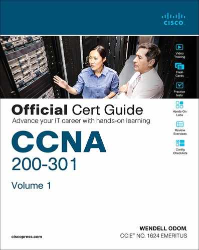
Although both a hub and a switch use the same cabling star topology, an Ethernet hub does not forward traffic like a switch. Ethernet hubs use physical layer processing to forward data. A hub does not interpret the incoming electrical signal as an Ethernet frame, look at the source and destination MAC address, and so on. Basically, a hub acts like a repeater, just with lots of ports. When a repeater receives an incoming electrical signal, it immediately forwards a regenerated signal out all the other ports except the incoming port. Physically, the hub just sends out a cleaner version of the same incoming electrical signal, as shown in Figure K-1, with Larry’s signal being repeated out the two ports on the right.
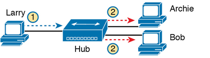
Figure K-1 10BASE-T (with a Hub): The Hub Repeats Out All Other Ports
Because of the physical layer operation used by the hub, the devices attached to the network must use carrier sense multiple access with collision detection (CSMA/CD) to take turns (as introduced at the end of Chapter 2). Note that the hub itself does not use CSMA/CD logic; the hub always receives an electrical signal and starts repeating a (regenerated) signal out all other ports, with no thought of CSMA/CD. So, although a hub’s logic works well to make sure all devices get a copy of the original frame, that same logic causes frames to collide. Figure K-2 demonstrates that effect, when the two devices on the right side of the figure send a frame at the same time, and the hub physically transmits both electrical signals out the port to the left (toward Larry).
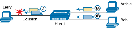
Figure K-2 Hub Operation Causing a Collision
Because a hub makes no attempt to prevent collisions, the devices connected to it all sit within the same collision domain. A collision domain is the set of NICs and device ports for which if they sent a frame at the same time, the frames would collide. In Figures K-1 and K-2, all three PCs are in the same collision domain, as well as the hub. Summarizing the key points about hubs:

The hub acts a multiport repeater, blindly regenerating and repeating any incoming electrical signal out all other ports, even ignoring CSMA/CD rules.
When two or more devices send at the same time, the hub’s actions cause an electrical collision, making both signals corrupt.
The connected devices must take turns by using carrier sense multiple access with collision detection (CSMA/CD) logic, so the devices share the bandwidth.
Hubs create a physical star topology.
Ethernet Transparent Bridges
From a design perspective, the introduction of 10BASE-T was a great improvement over the earlier types of Ethernet. It reduced cabling costs and cable installation costs, and improved the availability percentages of the network. But sitting here today, thinking of a LAN in which all devices basically have to wait their turn may seem like a performance issue, and it was. If Ethernet could be improved to allow multiple devices to send at the same time without causing a collision, Ethernet performance could be improved.
The first method to allow multiple devices to send at the same time was Ethernet transparent bridges. Ethernet transparent bridges, or simply bridges, made these improvements:
Bridges sat between hubs and divided the network into multiple collision domains.
Bridges increase the capacity of the entire Ethernet, because each collision domain is basically a separate instance of CSMA/CD, so each collision domain can have one sender at a time.
Figure K-3 shows the effect of building a LAN with two hubs, each separated by a bridge. The resulting two collision domains each support at most 10 Mbps of traffic each, compared to at most 10 Mbps if a single hub were used.

Figure K-3 Bridge Creates Two Collision Domains and Two Shared Ethernets
Bridges create multiple collision domains as a side effect of their forwarding logic. A bridge makes forwarding decisions just like a modern LAN switch; in fact, bridges were the predecessors of the modern LAN switch. Like switches, bridges hold Ethernet frames in memory, waiting to send out the outgoing interface based on CSMA/CD rules. In other cases, the bridge does not even need to forward the frame. For instance, if Fred sends a frame destined to Barney’s MAC address, then the bridge would never forward frames from the left to the right.
Ethernet Switches and Collision Domains
LAN switches perform the same basic core functions as bridges but at much faster speeds and with many enhanced features. Like bridges, switches segment a LAN into separate collision domains, each with its own capacity. And if the network does not have a hub, each single link in a modern LAN is considered its own collision domain, even if no collisions can actually occur in that case.
For example, Figure K-4 shows a simple LAN with a switch and four PCs. The switch creates four collision domains, with the ability to send at 100 Mbps in this case on each of the four links. And with no hubs, each link can run at full duplex, doubling the capacity of each link.
Figure K-4 Switch Creates Four Collision Domains and Four Ethernet Segments
Now take a step back for a moment and think about some facts about modern Ethernet LANs. Today, you build Ethernet LANs with Ethernet switches, not with Ethernet hubs or bridges. The switches connect to each other. And every single link is a separate collision domain.
As strange as it sounds, each of those collision domains in a modern LAN may also never have a collision. Any link that uses full duplex—that is, both devices on the link use full duplex—does not have collisions. In fact, running with full duplex is basically this idea: No collisions can occur between a switch and a single device, so we can turn off CSMA/CD by running full duplex.
Note
The routers in a network design also create separate collision domains, because frames entering or exiting one router LAN interface do not collide with frames on another of the router’s LAN interfaces.
The Impact of Collisions on LAN Design
So, what is the useful takeaway from this discussion about collision domains? A long time ago, collisions were normal in Ethernet, so analyzing an Ethernet design to determine where the collision domains were was useful. On the other end of the spectrum, a modern campus LAN that uses only switches (and no hubs or transparent bridges), and full duplex on all links, has no collisions at all. So does the collision domain term still matter today? And do we need to think about collisions even still today?
In a word, the term collision domain still matters, and collisions still matter, in that network engineers need to be ready to understand and troubleshoot exceptions. Whenever a port that could use full duplex (therefore avoiding collisions) happens to use half duplex—by incorrect configuration, by the result of autonegotiation, or any other reason—collisions can now occur. In those cases, engineers need to be able identify the collision domain.
Summarizing the key points about collision domains:
LAN switches place each separate interface into a separate collision domain.
LAN bridges, which use the same logic as switches, placed each interface into a separate collision domain.
Routers place each LAN interface into a separate collision domain. (The term collision domain does not apply to WAN interfaces.)
LAN hubs do not place each interface into a separate collision domain.
A modern LAN, with all LAN switches and routers, with full duplex on each link, would not have collisions at all.
In a modern LAN with all switches and routers, even though full duplex removes collisions, think of each Ethernet link as a separate collision domain when the need to troubleshoot arises.
Figure K-5 shows an example with a design that includes hubs, bridges, switches, and routers—a design that you would not use today, but it makes a good backdrop to remind us about which devices create separate collision domains.
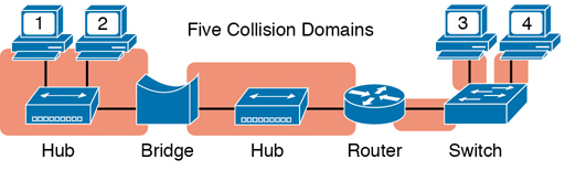
Figure K-5 Example of a Hub Not Creating Multiple Collision Domains, While Others Do
Ethernet Broadcast Domains
Take any Ethernet LAN, and pick any device. Then think of that device sending an Ethernet broadcast. An Ethernet broadcast domain is the set of devices to which that broadcast is delivered.
To begin, think about a modern LAN for a moment, and where a broadcast frame flows. Imagine that all the switches still used the switch default to put each interface into VLAN 1. As a result, a broadcast sent by any one device would be flooded to all devices connected to all switches (except for the device that sent the original frame). For instance, in Figure K-6, under the assumption that all ports are still assigned to VLAN 1, a broadcast would flow to all the devices shown in the figure.
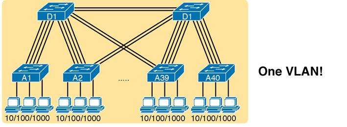
Figure K-6 A Single Large Broadcast Domain
Of all the common networking devices discussed in this book, only a router does not forward a LAN broadcast. Hubs of course forward broadcasts, because hubs do not even think about the electrical signal as an Ethernet frame. Bridges and switches use the same forwarding logic, flooding LAN broadcasts. Routers, as a side effect of their routing logic, do not forward Ethernet broadcast frames, so they separate a network into separate broadcast domains. Figure K-7 collects those thoughts into a single example.
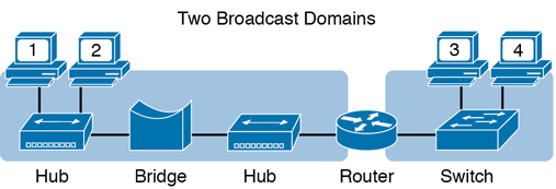
Figure K-7 Broadcast Domains Separated by a Router
By definition, broadcasts sent by a device in one broadcast domain are not forwarded to devices in another broadcast domain. In this example, there are two broadcast domains. The router does not forward a LAN broadcast sent by a PC on the left to the network segment on the right.
Virtual LANs
Routers create multiple broadcast domains mostly as a side effect of how IP routing works. While a network designer might set about to use more router interfaces for the purpose of making a larger number of smaller broadcast domains, that plan quickly consumes router interfaces. But a better tool exists, one that is integrated into LAN switches and consumes no additional ports: virtual LANs (VLAN).
By far, VLANs give the network designer the best tool for designing the right number of broadcast domains, of the right size, with the right devices in each. To appreciate how VLANs do that, you must first think about one specific definition of what a LAN is:
A LAN consists of all devices in the same broadcast domain.
With VLANs, a switch configuration places each port into a specific VLAN. The switches create multiple broadcast domains by putting some interfaces into one VLAN and other interfaces into other VLANs. The switch forwarding logic does not forward frames from a port in one VLAN out a port into another VLAN—so the switch separates the LAN into separate broadcast domains. Instead, routers must forward packets between the VLANs by using routing logic. So, instead of all ports on a switch forming a single broadcast domain, the switch separates them into many, based on configuration.
For perspective, think about how you would create two different broadcast domains with switches if the switches had no concept of VLANs. Without any knowledge of VLANs, a switch would receive a frame on one port and flood it out all the rest of its ports. Therefore, to make two broadcast domains, two switches would be used—one for each broadcast domain, as shown in Figure K-8.
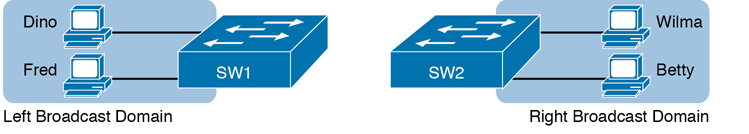
Figure K-8 Sample Network with Two Broadcast Domains and No VLANs
Alternatively, with a switch that understands VLANs, you can create multiple broadcast domains using a single switch. All you do is put some ports in one VLAN and some in the other. (The Cisco Catalyst switch interface subcommand to do so is switchport access vlan 2, for instance, to place a port into VLAN 2.) Figure K-9 shows the same two broadcast domains as in Figure K-8, now implemented as two different VLANs on a single switch.

Figure K-9 Sample Network with Two VLANs Using One Switch
This section briefly introduces the concept of VLANs, but Chapter 11, “Implementing Ethernet Virtual LANs,” discusses VLANs in more depth, including the details of how to configure VLANs in campus LANs.
The Impact of Broadcast Domains on LAN Design
Modern LAN designs try to avoid collisions, because collisions make performance worse. There is no benefit to keeping collisions in the network. However, a LAN design cannot remove broadcasts, because broadcast frames play an important role in many protocols. So when thinking about broadcast domains, the choices are more about tradeoffs rather than designing to remove broadcasts.
For just one perspective, just think about the size of a broadcast domain—that is, the number of devices in the same broadcast domain. A small number of large broadcast domains can lead to poor performance for the devices in that broadcast domain. However, moving in the opposite direction, to making a large number of broadcast domains each with just a few devices, leads to other problems.
Consider the idea of a too-large broadcast domain for a moment. When a host receives a broadcast, the host must process the received frame. All hosts need to send some broadcasts to function properly, so when a broadcast arrives, the NIC must interrupt the computer’s CPU to give the incoming message to the CPU. The CPU must spend time thinking about the received broadcast frame. (For example, IP Address Resolution Protocol [ARP] messages are LAN broadcasts, as mentioned in Chapter 4, “Fundamentals of IPv4 Addressing and Routing.”) So, broadcasts happen, which is good, but broadcasts do require all the hosts to spend time processing each broadcast frame. The more devices in the same broadcast domain, the more unnecessary interruptions of each device’s CPU.
This section of the book does not try to give a sweeping review of all VLAN design tradeoffs. Instead, you can see that the size of a VLAN should be considered, but many other factors come in to play as well. How big are the VLANs? How are the devices grouped? Do VLANs span across all switches or just a few? Is there any apparent consistency to the VLAN design, or is it somewhat haphazard? Answering these questions helps reveal what the designer was thinking, as well as what the realities of operating a network may have required.
Note
If you would like more detail about Cisco recommendations about what to put in what VLAN, which impacts the size of VLANs, read the most recent Cisco document, “Campus LAN validated design” by searching on that phrase at Cisco.com.
Summarizing the main points about broadcast domains:
Broadcasts exists, so be ready to analyze a design to define each broadcast domain, that is, each set of devices whose broadcasts reach the other devices in that domain.
VLANs by definition are broadcast domains created though configuration.
Routers, because they do not forward LAN broadcasts, create separate broadcast domains off their separate Ethernet interfaces.
Analyzing Campus LAN Topologies
The term campus LAN refers to the LAN created to support the devices in a building or in multiple buildings in somewhat close proximity to one another. For example, a company might lease office space in several buildings in the same office park. The network engineers can then build a campus LAN that includes switches in each building, plus Ethernet links between the switches in the buildings, to create a larger campus LAN.
When planning and designing a campus LAN, the engineers must consider the types of Ethernet available and the cabling lengths supported by each type. The engineers also need to choose the speeds required for each Ethernet segment. In addition, some thought needs to be given to the idea that some switches should be used to connect directly to end-user devices, whereas other switches might need to simply connect to a large number of these end-user switches. Finally, most projects require that the engineer consider the type of equipment that is already installed and whether an increase in speed on some segments is worth the cost of buying new equipment.
This second of three major sections of the chapter discusses the topology of a campus LAN design. Network designers do not just plug in devices to any port and connect switches to each other in an arbitrary way, like you might do with a few devices on the same table in a lab. Instead, there are known better ways to design the topology of a campus LAN, and this section introduces some of the key points and terms. The last major section of the chapter then looks at how to choose which Ethernet standard to use for each link in that campus LAN design, and why you might choose one versus another.
Two-Tier Campus Design (Collapsed Core)
To sift through all the requirements for a campus LAN, and then have a reasonable conversation about it with peers, most Cisco-oriented LAN designs use some common terminology to refer to the design. For this book’s purposes, you should be aware of some of the key campus LAN design terminology.
The Two-Tier Campus Design
Figure K-10 shows a typical design of a large campus LAN, with the terminology included in the figure. This LAN has around 1000 PCs connected to switches that support around 25 ports each. Explanations of the terminology follow the figure.
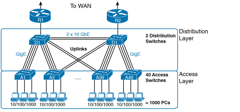
Figure K-10 Campus LAN with Design Terminology Listed
Cisco uses three terms to describe the role of each switch in a campus design: access, distribution, and core. The roles differ based on whether the switch forwards traffic from user devices and the rest of the LAN (access), or whether the switch forwards traffic between other LAN switches (distribution and core).
Access switches connect directly to end users, providing user device access to the LAN. Access switches normally send traffic to and from the end-user devices to which they are connected and sit at the edge of the LAN.
Distribution switches provide a path through which the access switches can forward traffic to each other. By design, each of the access switches connects to at least one distribution switch, typically to two distribution switches for redundancy. The distribution switches provide the service of forwarding traffic to other parts of the LAN. Note that most designs use at least two uplinks to two different distribution switches (as shown in Figure K-10) for redundancy.
The figure shows a two-tier design, with the tiers being the access tier (or layer) and the distribution tier (or layer). A two-tier design solves two major design needs:
Provides a place to connect end-user devices (the access layer, with access switches)
Connects the switches with a reasonable number of cables and switch ports by connecting all 40 access switches to two distribution switches
Topology Terminology Seen Within a Two-Tier Design
The exam topics happen to list a couple of terms about LAN and WAN topology and design, so this is a good place to pause to discuss those terms for a moment.
First, consider these more formal definitions of four topology terms:
Star: A design in which one central device connects to several others, so that if you drew the links out in all directions, the design would look like a star with light shining in all directions.
Full mesh: For any set of network nodes, a design that connects a link between each pair of nodes.
Partial mesh: For any set of network nodes, a design that connects a link between some pairs of nodes, but not all. In other words, a mesh that is not a full mesh.
Hybrid: A design that combines topology design concepts into a larger (typically more complex) design.
Armed with those formal definitions, note that the two-tier design is indeed a hybrid design that uses both a star topology at the access layer and a partial mesh at the distribution layer. To see why, consider Figure K-11. It redraws a typical access layer switch, but instead of putting the PCs all below the switch, it spreads them around the switch. Then on the right, a similar version of the same drawing shows why the term star might be used—the topology looks a little like a child’s drawing of a star.

Figure K-11 The Star Topology Design Concept in Networking
The distribution layer creates a partial mesh. If you view the access and distribution switches as nodes in a design, some nodes have a link between them, and some do not. Just refer to Figure K-10 and note that, by design, none of the access layer switches connect to each other.
Finally, a design could use a full mesh. However, for a variety of reasons beyond the scope of the design discussion here, a campus design typically does not need to use the number of links and ports required by a full mesh design. However, just to make the point, first consider how many links and switch ports would be required for a single link between nodes in a full mesh, with six nodes, as shown in Figure K-12.

Figure K-12 Using a Full Mesh at the Distribution Layer, 6 Switches, 15 Links
Even with only six switches, a full mesh would consume 15 links (and 30 switch ports—two per link).
Now think about a full mesh at the distribution layer for a design like Figure K-10, with 40 access switches and two distribution switches. Rather than drawing it and counting it, the number of links is calculated with this old math formula from high school: N(N – 1) / 2, or in this case, 42 * 41 / 2 = 861 links, and 1722 switch ports consumed among all switches.
For comparison’s sake, the partial mesh design of Figure K-10, with a pair of links from each access switch to each distribution switch, requires only 160 links and a total of 320 ports among all switches.
Three-Tier Campus Design (Core)
The two-tier design of Figure K-10, with a partial mesh of links at the distribution layer, happens to be the most common campus LAN design. It also goes by two common names: a two-tier design (for obvious reasons), and a collapsed core (for less obvious reasons). The term collapsed core refers to the fact that the two-tier design does not have a third tier, the core tier. This next topic examines a three-tier design that does have a core, for perspective.
Imagine your campus has just two or three buildings. Each building has a two-tier design inside the building, with a pair of distribution switches in each building and access switches spread around the building as needed. How would you connect the LANs in each building? Well, with just a few buildings, it makes sense to simply cable the distribution switches together, as shown in Figure K-13.
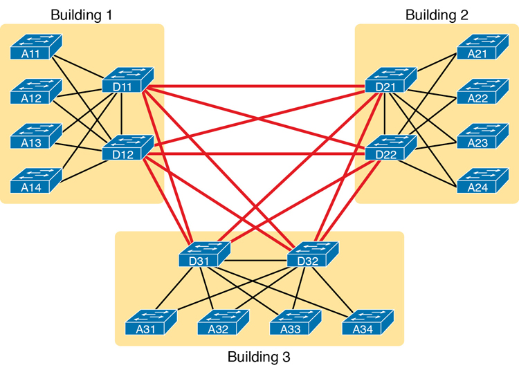
Figure K-13 Two-Tier Building Design, No Core, Three Buildings
The design in Figure K-13 works well, and many companies use this design. Sometimes the center of the network uses a full mesh, sometimes a partial mesh, depending on the availability of cables between the buildings.
However, a design with a third tier (a core tier) saves on switch ports and on cables in larger designs. And note that with the links between buildings, the cables run outside, are often more expensive to install, are almost always fiber cabling with more expensive switch ports, so conserving the number of cables used between buildings can help reduce costs.
A three-tier core design, unsurprisingly at this point, adds a few more switches (core switches), which provide one function: to connect the distribution switches. Figure K-14 shows the migration of the Figure K-13 collapsed core (that is, a design without a core) to a three-tier core design.


Figure K-14 Three-Tier Building Design (Core Design), Three Buildings
Note
The core switches sit in the middle of the figure. In the physical world, they often sit in the same room as one of the distribution switches, rather than in some purpose-built room in the middle of the office park. The figure focuses more on the topology rather than the physical location.
By using a core design, with a partial mesh of links in the core, you still provide connectivity to all parts of the LAN, and to the routers that send packets over the WAN, just with fewer links between buildings.
The following list summarizes the terms that describe the roles of campus switches:
Access: Provides a connection point (access) for end-user devices. Does not forward frames between two other access switches under normal circumstances.
Distribution: Provides an aggregation point for access switches, providing connectivity to the rest of the devices in the LAN, forwarding frames between switches, but not connecting directly to end-user devices.
Core: Aggregates distribution switches in very large campus LANs, providing very high forwarding rates for the larger volume of traffic due to the size of the network.
Topology Design Terminology
The ICND1 and CCNA exam topics specifically mention several network design terms related to topology. This next topic summarizes those key terms to connect the terms to the matching ideas.
First, consider Figure K-15, which shows a few of the terms. First, on the left, drawings often show access switches with a series of cables, parallel to each other. However, an access switch and its access links is often called a star topology. Why? Look at the redrawn access switch in the center of the figure, with the cables radiating out from the center. It does not look like a real star, but it looks a little like a child’s drawing of a star, hence the term star topology.

Figure K-15 LAN Design Terminology
The right side of the figure repeats a typical two-tier design, focusing on the mesh of links between the access and distribution switches. Any group of nodes that connect with more links than a star topology is typically called a mesh. In this case, the mesh is a partial mesh, because not all nodes have a direct link between each other. A design that connects all nodes with a link would be a full mesh.
Real networks make use of these topology ideas, but often a network combines the ideas together. For instance, the right side of Figure K-14 combines the star topology of the access layer with the partial mesh of the distribution layer. So you might hear these designs that combine concepts called a hybrid design.
Analyzing LAN Physical Standard Choices
When you look at the design of a network designed by someone else, you can look at all the different types of cabling used, the different types of switch ports, and the Ethernet standards used in each case. Then ask yourself: Why did they choose a particular type of Ethernet link for each link in the network? Asking that question, and investigating the answer, starts to reveal much about building the physical campus LAN.
The IEEE has done an amazing job developing Ethernet standards that give network designers many options. Two themes in particular have helped Ethernet grow over the long term:
The IEEE has developed many additional 802.3 standards for different types of cabling, different cable lengths, and for faster speeds.
All the physical standards rely on the same consistent data-link details, with the same standard frame formats. That means that one Ethernet LAN can use many types of physical links to meet distance, budget, and cabling needs.
For example, think about the access layer of the generic design drawings, but now think about cabling and Ethernet standards. In practice, access layer switches sit in a locked wiring closet somewhere on the same floor as the end user devices. Electricians have installed unshielded twisted-pair (UTP) cabling used at the access layer, running from that wiring closet to each wall plate at each office, cubicle, or any place where an Ethernet device might need to connect to the LAN. The type and quality of the cabling installed between the wiring closet and each Ethernet outlet dictate what Ethernet standards can be supported. Certainly, whoever designed the LAN at the time the cabling was installed thought about what type of cabling was needed to support the types of Ethernet physical standards that were going to be used in that LAN.
Ethernet Standards
Over time, the IEEE has continued to develop and release new Ethernet standards, for new faster speeds and to support new and different cabling types and cable lengths. Figure K-16 shows some insight into Ethernet speed improvements over the years. The early standards up through the early 1990s ran at 10 Mbps, with steadily improving cabling and topologies. Then, with the introduction of Fast Ethernet (100 Mbps) in 1995, the IEEE began ramping up the speeds steadily over the next few decades, continuing even until today.

Figure K-16 Ethernet Standards Timeline
Note
Often, the IEEE first introduces support for the next higher speed using some forms of fiber optic cabling, and later, sometimes many years later, the IEEE completes the work to develop standards to support the same speed on UTP cabling. Figure K-16 shows the earliest standards for each speed, no matter what cabling.
When the IEEE introduces support for a new type of cabling, or a faster speed, they create a new standard as part of 802.3. These new standards have a few letters behind the name. So, when speaking of the standards, sometimes you might refer to the standard name (with letters). For instance, the IEEE standardized Gigabit Ethernet support using inexpensive UTP cabling in standard 802.3ab. However, more often, engineers refer to that same standard as 1000BASE-T or simply Gigabit Ethernet. Table K-1 lists some of the IEEE 802.3 physical layer standards and related names for perspective.
Table K-1 IEEE Physical Layer Standards
Original IEEE Standard |
Shorthand Name |
Informal Names |
Speed |
Typical Cabling |
|---|---|---|---|---|
802.3i |
10BASE-T |
Ethernet |
10 Mbps |
UTP |
802.3u |
100BASE-T |
Fast Ethernet |
100 Mbps |
UTP |
802.3z |
1000BASE-X |
Gigabit Ethernet, GigE |
1000 Mbps (1 Gbps) |
Fiber |
802.3ab |
1000BASE-T |
Gigabit Ethernet, GigE |
1000 Mbps (1 Gbps) |
UTP |
802.3ae |
10GBASE-X |
10 GigE |
10 Gbps |
Fiber |
802.3an |
10GBASE-T |
10 GigE |
10 Gbps |
UTP |
802.3ba |
40GBASE-X |
40 GigE |
40 Gbps |
Fiber |
802.3ba |
100GBASE-X |
100 GigE |
100 Gbps |
Fiber |
Choosing the Right Ethernet Standard for Each Link
When designing an Ethernet LAN, you can and should think about the topology, with an access layer, a distribution layer, and possibly a core layer. But thinking about the topology does not tell you which specific standards to follow for each link. Ultimately, you need to pick which Ethernet standard to use for each link, based on the following kinds of facts about each physical standard:
The speed
The maximum distance allowed between devices when using that standard/cabling
The cost of the cabling and switch hardware
The availability of that type of cabling already installed at your facilities
Consider the three most common types of Ethernet today (10BASE-T, 100BASE-T, and 1000BASE-T). They all have the same 100-meter UTP cable length restriction. They all use UTP cabling. However, not all UTP cabling meets the same quality standard, and as it turns out, the faster the Ethernet standard, the higher the required cable quality category needed to support that standard. As a result, some buildings might have better cabling that supports speeds up through Gigabit Ethernet, whereas some buildings may support only Fast Ethernet.
The Telecommunications Industry Association (TIA; tiaonline.org) defines Ethernet cabling quality standards. Each Ethernet UTP standard lists a TIA cabling quality (called a category) as the minimum category that the standard supports. For example, 10BASE-T allows for Category 3 (CAT3) cabling or better. 100BASE-T requires higher-quality CAT5 cabling, and 1000BASE-T requires even higher-quality CAT5e cabling. (The TIA standards follow a general “higher number is better cabling” in their numbering.) For instance, if an older facility had only CAT5 cabling installed between the wiring closets and each cubicle, the engineers would have to consider upgrading the cabling to fully support Gigabit Ethernet. Table K-2 lists the more common types of Ethernet and their cable types and length limitations.
Table K-2 Ethernet Types, Media, and Segment Lengths (Per IEEE)
Ethernet Type |
Media |
Maximum Segment Length |
|---|---|---|
10BASE-T |
TIA CAT3 or better, 2 pairs |
100 m (328 feet) |
100BASE-T |
TIA CAT5 UTP or better, 2 pairs |
100 m (328 feet) |
1000BASE-T |
TIA CAT5e UTP or better, 4 pairs |
100 m (328 feet) |
10GBASE-T |
TIA CAT6a UTP or better, 4 pairs |
100 m (328 feet) |
10GBASE-T1 |
TIA CAT6 UTP or better, 4 pairs |
38–55 m (127–180 feet) |
1000BASE-SX |
Multimode fiber |
550 m (1800 feet) |
1000BASE-LX |
Multimode fiber |
550 m (1800 feet) |
1000BASE-LX |
9-micron single-mode fiber |
5 km (3.1 miles) |
1 The option for 10GBASE-T with slightly less quality CAT6 cabling, but at shorter distances, is an attempt to support 10Gig Ethernet for some installations with CAT6 installed cabling.
Ethernet defines standards for using fiber optic cables as well. Fiber optic cables include ultrathin strands of glass through which light can pass. To send bits, the switches can alternate between sending brighter and dimmer light to encode 0s and 1s on the cable.
Generally comparing optical cabling versus UTP cabling Ethernet standards, two obvious points stand out. Optical standards allow much longer cabling, while generally costing more for the cable and the switch hardware components. Optical cables experience much less interference from outside sources compared to copper cables, which allows for longer distances.
When considering optical Ethernet links, many standards exist, but with two general categories. Comparing the two, the cheaper options generally support distances into the hundreds of meters, using less expensive light-emitting diodes (LED) to transmit data. Other optical standards support much longer distances into multiple kilometers, using more expensive cabling and using lasers to transmit the data. The trade-off is basic: For a given link, how long does the cable need to run, what standards support that distance, and which is the least expensive to meet that need?
In reality, most engineers remember only the general facts from tables like Table K-2: 100 meters for UTP, about 500 meters for multimode fiber, and about 5000 meters for some single mode fiber Ethernet standards. When it is time to get serious about designing the details of each link, the engineer must get into the details, calculating the length of each cable based on its path through the building, and so on.
Wireless LANs Combined with Wired Ethernet
Modern campus LANs include a large variety of wireless devices that connect to the access layer of the LAN. As it turns out, Cisco organizes wireless LANs into a separate certification track—CCNA, CCNP, and CCIE Wireless—so the CCNA R&S track has traditionally had only a little wireless LAN coverage. The current version of the exams are no different, with this one exam CCNA R&S topic mentioning wireless LANs:
Describe the impact of infrastructure components in an enterprise network: Access points and wireless controllers
Do not let that small mention of wireless technology make you think that wireless is less important than Ethernet. In fact, there may be more wireless devices than wired at the access layer of today’s enterprise networks. Both are important; Cisco just happens to keep the educational material for wireless in a separate certification track.
This last topic in the chapter examines that one exam topic that mentions two wireless terms.
Home Office Wireless LANs
First, the IEEE defines both Ethernet LANs and Wireless LANs. In case it was not obvious yet, all Ethernet standards use cables—that is, Ethernet defines wired LANs. The IEEE 802.11 working group defines Wireless LANs, also called Wi-Fi per a trademarked term from the Wi-Fi Alliance (wi-fi.org), a consortium that helps to encourage wireless LAN development in the marketplace.
Most of you have used Wi-Fi, and may use it daily. Some of you may have set it up at home, with a basic setup as shown in Figure K-17. In a home, you probably used a single consumer device called a wireless router. One side of the device connects to the Internet, while the other side connects to the devices in the home. In the home, the devices can connect either with Wi-Fi or with a wired Ethernet cable.
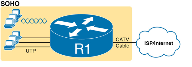
Figure K-17 A Typical Home Wired and Wireless LAN
While the figure shows the hardware as a single router icon, internally, that one wireless router acts like three separate devices you would find in an enterprise campus:
An Ethernet switch, for the wired Ethernet connections
A wireless access point (AP), to communicate with the wireless devices and forward the frames to/from the wired network
A router, to route IP packets to/from the LAN and WAN (Internet) interfaces
Figure K-18 repeats the previous figure, breaking out the internal components as if they were separate physical devices, just to make the point that a single consumer wireless router acts like several different devices.
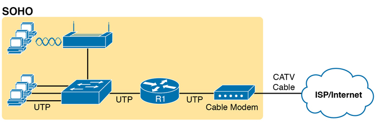
Figure K-18 A Representation of the Functions Inside a Consumer Wireless Routing Product
In a small office/home office (SOHO) wireless LAN, the wireless AP acts autonomously, doing all the work required to create and control the wireless LAN (WLAN). (In most enterprise WLANs, the AP does not act autonomously.) In other words, the autonomous AP communicates with the various wireless devices using 802.11 protocols and radio waves. It uses Ethernet protocols on the wired side. It converts between the differences in header formats between 802.11 and 802.3 frames before forwarding to/from 802.3 Ethernet and 802.11 wireless frames.
Beyond those basic forwarding actions, the autonomous AP must perform a variety of control and management functions. The AP authenticates new devices, defines the name of the WLAN (called a service set ID, or SSID), and other details.
Enterprise Wireless LANs and Wireless LAN Controllers
If you connect to your WLAN at home from your tablet, phone, or laptop, and then walk down the street with that same device, you expect to lose your Wi-Fi connection at some point. You do not expect to somehow automatically connect to a neighbor’s Wi-Fi network, particularly if they did the right thing and set up security functions on their AP to prevent others from accessing their home Wi-Fi network. The neighborhood does not create one WLAN supported by the devices in all the houses and apartments; instead, it has lots of little autonomous WLANs.
However, in an enterprise, the opposite needs to happen. We want people to be able to roam around the building and office campus and keep connected to the Wi-Fi network. This requires many APs, which work together rather than autonomously to create one wireless LAN.
First, think about the number of APs an enterprise might need. Each AP can cover only a certain amount of space, depending on a large number of conditions and the wireless standard. (The size varies, but the distances sit in the 100 to 200 feet range.) At the same time, you might have the opposite problem; you may just need lots of APs in a small space, just to add capacity to the WLAN. Much of the time spent designing WLANs revolves around deciding how many APs to place in each space, and of what types, to handle the traffic.
Note
If you have not paid attention before, start looking around the ceilings of any new buildings you enter, even retail stores, and look for their wireless APs.
Each AP must then connect to the wired LAN, because most of the destinations that wireless users need to communicate with sit in the wired part of the network. In fact, the APs typically sit close to where users sit, for obvious reasons, so the APs connect to the same access switches as the end users, as shown in Figure K-19.
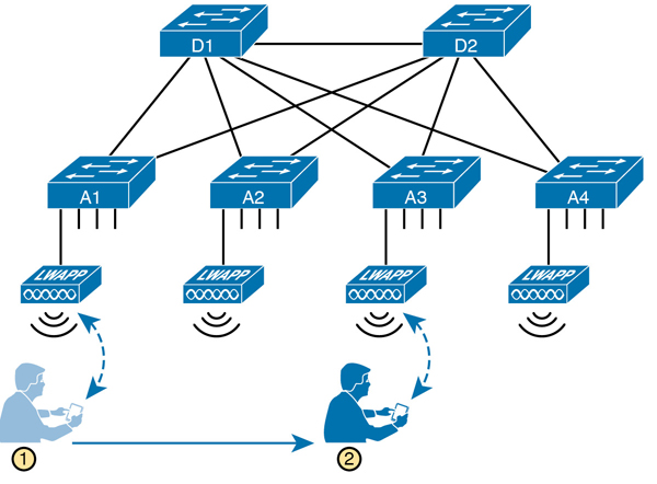
Figure K-19 Campus LAN, Multiple Lightweight APs, with Roaming
Now imagine that is you at the bottom of the figure. Your smartphone has Wi-Fi enabled, so that when you walk into work, your phone automatically connects to the company WLAN. You roam around all day, going to meetings, lunch, and so on. All day long you stay connected to the company WLAN, but your phone connects to and uses many different APs.
Supporting roaming and other enterprise WLAN features by using autonomous APs can be difficult at best. You could imagine that if you had a dozen APs per floor, you might have hundreds of APs in a campus—all of which need to know about that one WLAN.
The solution: remove all the control and management features from the APs, and put them in one centralized place, called a Wireless Controller, or Wireless LAN Controller (WLC). The APs no longer act autonomously, but instead act as lightweight APs (LWAPs), just forwarding data between the wireless LAN and the WLC. All the logic to deal with roaming, defining WLANs (SSIDs), authentication, and so on happens in the centralized WLC rather than on each AP. Summarizing:
Wireless LAN controller: Controls and manages all AP functions (for example, roaming, defining WLANs, authentication)
Lightweight AP (LWAP): Forwards data between the wired and wireless LAN, and specifically forwarding data through the WLC using a protocol like Control And Provisioning of Wireless Access Points (CAPWAP)
With the WLC and LWAP design, the combined LWAPs and WLC can create one big wireless network, rather than creating a multitude of disjointed wireless networks. The key to making it all work is that all wireless traffic flows through the WLC, as shown in Figure K-20. (The LWAPs commonly use a protocol called CAPWAP, by the way.)
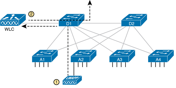
Figure K-20 Campus LAN, Multiple Lightweight APs, with Roaming
By forwarding all the traffic through the WLC, the WLC can make the right decisions across the enterprise. For example, you might create a marketing WLAN, an engineering WLAN, and so on, and all the APs know about and support those multiple different WLANs. Users that connect to the engineering WLAN should use the same authentication rules regardless of which AP they use—and the WLC makes that possible. Or consider roaming for a moment. If at one instant a packet arrives for your phone, and you are associated with AP1, and when the next packet arrives over the wired network you are now connected to AP4, how could that packet be delivered through the network? Well, it always goes to the WLC, and because the WLC keeps in contact with the APs and knows that your phone just roamed to another AP, the WLC knows where to forward the packet.