Appendix P. LAN Troubleshooting
Note
This appendix contains an entire chapter that was published as a chapter in one of the past editions of this book or a related book. The author includes this appendix with the current edition as extra reading for anyone interested in learning more. However, note that the content in this appendix has not been edited since it was published in the earlier edition, so references to exams and exam topics, and to other chapters, will be outdated. This appendix was previously published as Chapter 4 of the book CCNA Routing and Switching ICND2 200-105 Official Cert Guide, published in 2016.
This chapter discusses the LAN topics discussed in depth in the first three chapters, plus a few prerequisite topics, from a troubleshooting perspective.
Troubleshooting for any networking topic requires a slightly different mindset as compared to thinking about configuration and verification. When thinking about configuration and verification, it helps to think about basic designs, learn how to configure the feature correctly, and learn how to verify the correct configuration is indeed working correctly. However, to learn how to troubleshoot, you need to think about symptoms when the design is incorrect, or if the configuration does not match the good design. What symptoms occur when you make one type of mistake or another? This chapter looks at the common types of mistakes, and works through how to look at the status with show commands to find those mistakes.
This chapter breaks the material into four major sections. The first section tackles the largest topic, STP troubleshooting. STP is not likely to fail as a protocol; instead, STP may not be operating as designed, so the task is to find how STP is currently working and discover how to then make the configuration implement the correct design. The second major section then moves on to Layer 2 EtherChannels, which have a variety of small potential problems that can prevent the dynamic formation of an EtherChannel.
The third major section of the chapter focuses on the data plane forwarding of Ethernet frames on LAN switches, in light of VLANs, trunks, STP, and EtherChannels. That same section reviews the Layer 2 forwarding logic of a switch in light of these features. The fourth and final major section then examines VLAN and trunking issues, and how those issues impact switch forwarding.
Note that a few of the subtopics listed within the exam topics at the beginning of this chapter are not discussed in this chapter. This chapter does not discuss VTP beyond its basic features or Layer 3 EtherChannels.
Foundation Topics
Troubleshooting STP
STP questions tend to intimidate many test takers. STP uses many rules, with tiebreakers in case one rule ends with a tie. Without much experience with STP, people tend to distrust their own answers. Also, even those of us with networking jobs already probably do not troubleshoot STP very often, because STP works well. Often, troubleshooting STP is not about STP failing to do its job but rather about STP working differently than designed, with a different root switch, or different root ports (RP), and so on. Seldom does STP troubleshooting begin with a case in which STP has failed to prevent a loop.
This section reviews the rules for STP, while emphasizing some important troubleshooting points. In particular, this section takes a closer look at the tiebreakers that STP uses to make decisions. It also makes some practical suggestions about how to go about answering exam questions such as “which switch is the root switch?”
Determining the Root Switch
Determining the STP root switch is easy if you know all the switches’ BIDs: Just pick the lowest value. If the question lists the priority and MAC address separately, as is common in some show command output, pick the switch with the lowest priority, or in the case of a tie, pick the lower MAC address value.
And just to be extra clear, STP does not have nor need a tiebreaker for electing the root switch. The BID uses a switch universal MAC address as the last 48 bits of the BID. These MAC addresses are unique in the universe, so there should never be identical BIDs or the need for a tiebreaker.
For the exam, a question that asks about the root switch might not be so simple as listing a bunch of BIDs and asking you which one is “best.” A more likely question is a simulator (sim) question in which you have to do any show commands you like or a multiple choice question that lists the output from only one or two commands. Then you have to apply the STP algorithm to figure out the rest.
When faced with an exam question using a simulator, or just the output in an exhibit, use a simple strategy of ruling out switches, as follows:
Step 1. Begin with a list or diagram of switches, and consider all as possible root switches.
Step 2. Rule out any switches that have an RP (show spanning-tree, show spanning-tree root), because root switches do not have an RP.
Step 3. Always try show spanning-tree, because it identifies the local switch as root directly: “This switch is the root” on the fifth line of output.
Step 4. Always try show spanning-tree root, because it identifies the local switch as root indirectly: The RP column is empty if the local switch is the root.
Step 5. When using a sim, rather than try switches randomly, chase the RPs. For example, if starting with SW1, and SW1’s G0/1 is an RP, next try the switch on the other end of SW1’s G0/1 port.
Step 6. When using a sim, use show spanning-tree vlan x on a few switches and record the root switch, RP, and designated port (DP). This strategy can quickly show you most STP facts.
The one step in this list that most people ignore is the idea of ruling out switches that have an RP. Root switches do not have an RP, so any switch with an RP can be ruled out as not being the root switch for that VLAN. Example P-1 shows two commands on switch SW2 in some LAN that confirms that SW2 has an RP and is therefore not the root switch.
Example P-1 Ruling Out Switches as Root Based on Having a Root Port
SW2# show spanning-tree vlan 20 root

                                           Root Hello Max Fwd
Vlan                   Root ID             Cost  Time Age Dly  Root Port
---------------- -------------------- --------- ----- --- ---  ------------
VLAN0020         32788 1833.9d7b.0e80         4    2   20  15  Gi0/2

SW2# show spanning-tree vlan 20

VLAN0020
  Spanning tree enabled protocol ieee
  Root ID    Priority    32788
             Address     1833.9d7b.0e80
             Cost        4
             Port        26 (GigabitEthernet0/2)
             Hello Time   2 sec  Max Age 20 sec  Forward Delay 15 sec

  Bridge ID  Priority    32788  (priority 32768 sys-id-ext 20)
             Address     1833.9d7b.1380
             Hello Time   2 sec  Max Age 20 sec  Forward Delay 15 sec
             Aging Time  15  sec

Interface           Role Sts Cost      Prio.Nbr Type
------------------- ---- --- --------- -------- --------------------------------
Gi0/1               Desg FWD 4         128.25   P2p
Gi0/2               Root FWD 4         128.26   P2p
Both commands identify SW2’s G0/2 port as its RP, so if you follow the suggestions, the next switch to try in a sim question would be the switch on the other end of SW2’s G0/2 interface.
Determining the Root Port on Nonroot Switches
Determining the RP of a switch when show command output is available is relatively easy. As shown recently in Example P-1, both show spanning-tree and show spanning-tree root list the root port of the local switch, assuming it is not the root switch. The challenge comes more when an exam question makes you think through how the switches choose the RP based on the root cost of each path to the root switch, with some tiebreakers as necessary.
As a review, each nonroot switch has one, and only one, RP for a VLAN. To choose its RP, a switch listens for incoming Hello bridge protocol data units (BPDU). For each received Hello, the switch adds the cost listed in the hello BPDU to the cost of the incoming interface (the interface on which the Hello was received). That total is the root cost over that path. The lowest root cost wins, and the local switch uses its local port that is part of the least root cost path as its root port.
Most humans can analyze what STP chooses by using a network diagram and a slightly different algorithm. Instead of thinking about Hello messages and so on, approach the question as this: the sum of all outgoing port costs between the nonroot switch and the root. Repeating a familiar example, with a twist, Figure P-1 shows the calculation of the root cost. Note that SW3’s Gi0/1 port has yet again had its cost configured to a different value.
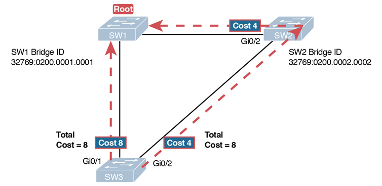
Figure P-1 SW3’s Root Cost Calculation Ends in a Tie
STP Tiebreakers When Choosing the Root Port
Figure P-1 shows the easier process of adding the STP costs of the outgoing interfaces over each from SW3, a nonroot, to SW1, the root. It also shows a tie (on purpose), to talk about the tiebreakers.
When a switch chooses its root port, the first choice is to choose the local port that is part of the least root cost path. When those costs tie, the switch picks the port connected to the neighbor with the lowest BID. This tiebreaker usually breaks the tie, but not always. So, for completeness, the three tiebreakers are, in the order a switch uses them, as follows:
Choose based on the lowest neighbor bridge ID.
Choose based on the lowest neighbor port priority.
Choose based on the lowest neighbor internal port number.
(Note that the switch only considers the root paths that tie when thinking about these tiebreakers.)
For example, Figure P-1 shows that SW3 is not root and that its two paths to reach the root tie with their root costs of 8. The first tiebreaker is the lowest neighbor’s BID. SW1’s BID value is lower than SW2’s, so SW3 chooses its G0/1 interface as its RP in this case.
The last two RP tiebreakers come into play only when two switches connect to each other with multiple links, as shown in Figure P-2. In that case, a switch receives Hellos on more than one port from the same neighboring switch, so the BIDs tie.

Figure P-2 Topology Required for the Last Two Tiebreakers for Root Port
In this particular example, SW2 becomes root, and SW1 needs to choose its RP. SW1’s port costs tie, at 19 each, so SW1’s root cost over each path will tie at 19. SW2 sends Hellos over each link to SW1, so SW1 cannot break the tie based on SW1’s neighbor BID because both list SW2’s BID. So, SW1 has to turn to the other two tiebreakers.
Note
In real life, most engineers would put these two links into an EtherChannel.
The next tiebreaker is a configurable option: the neighboring switch’s port priority on each neighboring switch interface. Cisco switch ports default to a setting of 128, with a range of values from 0 through 255, with lower being better (as usual). In this example, the network engineer has set SW2’s F0/16 interface with the spanning-tree vlan 10 port-priority 112 command. SW1 learns that the neighbor has a port priority of 112 on the top link and 128 on the bottom, so SW1 uses its top (F0/14) interface as the root port.
If the port priority ties, which it often does due to the default values, STP relies on an internal port numbering on the neighbor. Cisco switches assign an internal integer to identify each interface on the switch. The nonroot looks for the neighbor’s lowest internal port number (as listed in the Hello messages) and chooses its RP based on the lower number.
Cisco switches use an obvious numbering, with Fa0/1 having the lowest number, then Fa0/2, then Fa0/3, and so on. So, in Figure P-2, SW2’s Fa0/16 would have a lower internal port number than Fa0/17; SW1 would learn those numbers in the Hello; and SW1 would use its Fa0/14 port as its RP.
Suggestions for Attacking Root Port Problems on the Exam
Exam questions that make you think about the RP can be easy if you know where to look and the output of a few key commands is available. However, the more conceptual the question, the more you have to calculate the root cost over each path, correlate that to different show commands, and put the ideas together. The following list makes a few suggestions about how to approach STP problems on the exam:
If available, look at the show spanning-tree and show spanning-tree root commands. Both commands list the root port and the root cost (see Example P-1).
The show spanning-tree command lists cost in two places: the root cost at the top, in the section about the root switch; and the interface cost, at the bottom, in the per-interface section. Be careful, though; the cost at the bottom is the interface cost, not the root cost!
For problems where you have to calculate a switch’s root cost:
Memorize the default cost values: 100 for 10 Mbps, 19 for 100 Mbps, 4 for 1 Gbps, and 2 for 10 Gbps.
Look for any evidence of the spanning-tree cost configuration command on an interface, because it overrides the default cost. Do not assume default costs are used.
When you know a default cost is used, if you can, check the current actual speed as well. Cisco switches choose STP cost defaults based on the current speed, not the maximum speed.
Determining the Designated Port on Each LAN Segment
Each LAN segment has a single switch that acts as the designated port (DP) on that segment. On segments that connect a switch to a device that does not even use STP—for example, segments connecting a switch to a PC or a router—the switch always wins, because it is the only device sending a Hello onto the link. However, links with two switches require a little more work to discover which should be the DP. By definition:
Step 1. For switches connected to the same LAN segment, the switch with the lowest cost to reach the root, as advertised in the Hello they send onto the link, becomes the DP on that link.
Step 2. In case of a tie, among the switches that tied on cost, the switch with the lowest BID becomes the DP.
For example, consider Figure P-3. This figure notes the root, RPs, and DPs and each switch’s least cost to reach the root over its respective RP.
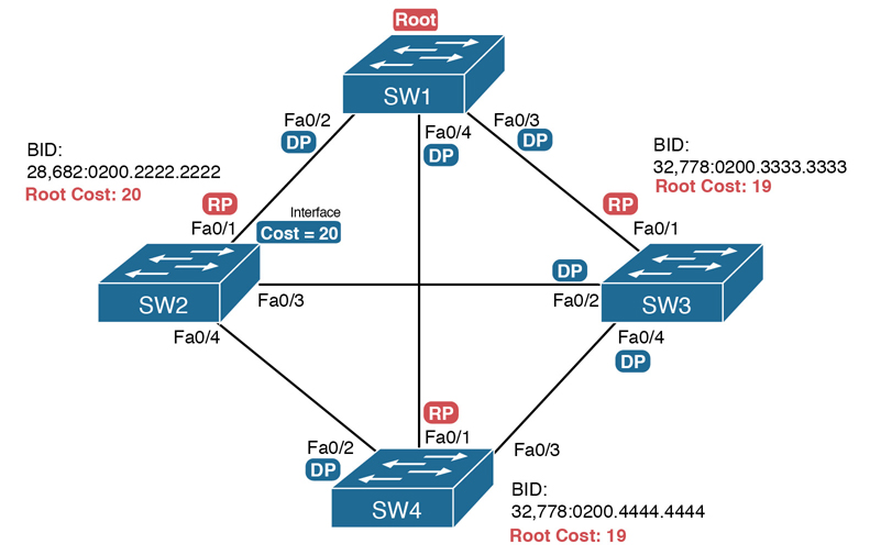
Figure P-3 Picking the DPs
Focus on the segments that connect the nonroot switches for a moment:
SW2–SW4 segment: SW4 wins because of its root cost of 19, compared to SW2’s root cost of 20.
SW2–SW3 segment: SW3 wins because of its root cost of 19, compared to SW2’s root cost of 20.
SW3–SW4 segment: SW3 and SW4 tie on root cost, both with root cost 19. SW3 wins due to its better (lower) BID value.
Interestingly, SW2 loses and does not become DP on the links to SW3 and SW4 even though SW2 has the better (lower) BID value. The DP tiebreaker does use the lowest BID, but the first DP criteria is the lowest root cost, and SW2’s root cost happens to be higher than SW3’s and SW4’s.
Note
A single switch can connect two or more interfaces to the same collision domain, and compete to become DP, if hubs are used. In such cases, two different switch ports on the same switch tie, the DP choice uses the same two final tiebreakers as used with the RP selection: the lowest interface STP priority, and if that ties, the lowest internal interface number.
Suggestions for Attacking Designated Port Problems on the Exam
As with exam questions asking about the RP, exam questions that make you think about the DP can be easy if you know where to look and the output of a few key commands is available. However, the more conceptual the question, the more you have to think about the criteria for choosing the DP: first the root cost of the competing switches, and then the better BID if they tie based on root cost.
The following list gives some tips to keep in mind when digging into a given DP issue. Some of this list repeats the suggestions for finding the RP, but to be complete, this list includes each idea as well.
If available, look at the show spanning-tree commands, at the list of interfaces at the end of the output. Then, look for the Role column, and look for Desg, to identify any DPs.
Identify the root cost of a switch directly by using the show spanning-tree command. But be careful! This command lists the cost in two places, and only the mention at the top, in the section about the root, lists the root cost.
For problems where you have to calculate a switch’s root cost, do the following:
Memorize the default cost values: 100 for 10 Mbps, 19 for 100 Mbps, 4 for 1 Gbps, and 2 for 10 Gbps.
Look for any evidence of the spanning-tree cost configuration command on an interface, because it overrides the default cost. Do not assume default costs are used.
When you know a default cost is used, if you can, check the current actual speed as well. Cisco switches choose STP cost defaults based on the current speed, not the maximum speed.
STP Convergence
STP puts each RP and DP into a forwarding state, and ports that are neither RP nor DP into a blocking state. Those states may remain as is for days, weeks, or months. But at some point, some switch or link will fail, a link may change speeds (changing the STP cost), or the STP configuration may change. Any of these events can cause switches to repeat their STP algorithm, which may in turn change their own RP and any ports that are DPs.
When STP converges based on some change, not all the ports have to change their state. For instance, a port that was forwarding, if it still needs to forward, just keeps on forwarding. Ports that were blocking that still need to block keep on blocking. But when a port needs to change state, something has to happen, based on the following rules:

For interfaces that stay in the same STP state, nothing needs to change.
For interfaces that need to move from a forwarding state to a blocking state, the switch immediately changes the state to blocking.
For interfaces that need to move from a blocking state to a forwarding state, the switch first moves the interface to listening state, then learning state, each for the time specified by the forward delay timer (default 15 seconds). Only then is the interface placed into forwarding state.
Because the transition from blocking to forwarding does require some extra steps, you should be ready to respond to conceptual questions about the transition.
Troubleshooting Layer 2 EtherChannel
EtherChannels can prove particularly challenging to troubleshoot for a couple of reasons. First, you have to be careful to match the correct configuration, and there are many more incorrect configuration combinations than there are correct combinations. Second, many interface settings must match on the physical links, both on the local switch and on the neighboring switch, before a switch will add the physical link to the channel. This second major section in the chapter works through both sets of issues.
Incorrect Options on the channel-group Command
The rules for the small set of working configuration options on the channel-group command can be summarized as follows, for a single EtherChannel:
On the local switch, all the channel-group commands for all the physical interfaces must use the same channel-group number.
The channel-group number can be different on the neighboring switches.
If using the on keyword, you must use it on the corresponding interfaces of both switches.
If you use the desirable keyword on one switch, the switch uses PAgP; the other switch must use either desirable or auto.
If you use the active keyword on one switch, the switch uses LACP; the other switch must use either active or passive.
These rules summarize the correct configuration options, but the options actually leave many more incorrect choices. The following list shows some incorrect configurations that the switches allow, even though they would result in the EtherChannel not working. The list compares the configuration on one switch to another based on the physical interface configuration. Each lists the reasons why the configuration is incorrect.
Configuring the on keyword on one switch, and desirable, auto, active, or passive on the other switch. The on keyword does not enable PAgP, and does not enable LACP, and the other options rely on PAgP or LACP.
Configuring the auto keyword on both switches. Both use PAgP, but both wait on the other switch to begin negotiations.
Configuring the passive keyword on both switches. Both use LACP, but both wait on the other switch to begin negotiations.
Configuring the active keyword on one switch and either desirable or auto on the other switch. The active keyword uses LACP, whereas the other keywords use PAgP.
Configuring the desirable keyword on one switch and either active or passive on the other switch. The desirable keyword uses PAgP, whereas the other keywords use LACP.
Example P-2 shows an example that matches the last item in the list. In this case, SW1’s two ports (F0/14 and F0/15) have been configured with the desirable keyword, and SW2’s matching F0/16 and F0/17 have been configured with the active keyword. The example lists some telling status information about the failure, with notes following the example.
Example P-2 Incorrect Configuration Using Mismatched PortChannel Protocols
SW1# show etherchannel summary
Flags:  D - down        P - bundled in port-channel
        I - stand-alone s - suspended
        H - Hot-standby (LACP only)
        R - Layer3      S - Layer2
        U - in use      f - failed to allocate aggregator

        M - not in use, minimum links not met
        u - unsuitable for bundling
        w - waiting to be aggregated
        d - default port


Number of channel-groups in use: 1
Number of aggregators:           1

Group  Port-channel  Protocol    Ports
------+-------------+-----------+-----------------------------------------------
1      Po1(SD)         PAgP      Fa0/14(I)   Fa0/15(I)
SW1# show interfaces status | include Po|14|15

Port      Name               Status       Vlan       Duplex  Speed Type
Fa0/14                       connected    301        a-full  a-100 10/100BaseTX
Fa0/15                       connected    301        a-full  a-100 10/100BaseTX
Po1                          notconnect   unassigned   auto   auto
Start at the top, in the legend of the show etherchannel summary command. The D code letter means that the channel itself is down, with S meaning that the channel is a Layer 2 EtherChannel. Code I means that the physical interface is working independently from the PortChannel (described as “stand-alone”). Then, the bottom of that command’s output highlights PortChannel 1 (Po1) as Layer 2 EtherChannel in a down state (SD), with F0/14 and F0/15 as stand-alone interfaces (I).
Interestingly, because the problem is a configuration mistake, the two physical interfaces still operate independently, as if the PortChannel did not exist. The last command in the example shows that while the PortChannel 1 interface is down, the two physical interfaces are in a connected state.
Note
As a suggestion for attacking EtherChannel problems on the exam, rather than memorizing all the incorrect configuration options, concentrate on the list of correct configuration options. Then look for any differences between a given question’s configuration as compared to the known correct configurations and work from there.
Configuration Checks Before Adding Interfaces to EtherChannels
Even when the channel-group commands have all been configured correctly, other configuration settings can cause problems as well. This last topic examines those configuration settings and their impact.
First, a local switch checks each new physical interface that is configured to be part of an EtherChannel, comparing each new link to the existing links. That new physical interface’s settings must be the same as the existing links’ settings; otherwise, the switch does not add the new link to the list of approved and working interfaces in the channel. That is, the physical interface remains configured as part of the PortChannel, but it is not used as part of the channel, often being placed into some nonworking state.
The list of items the switch checks includes the following:
Speed
Duplex
Operational access or trunking state (all must be access, or all must be trunks)
If an access port, the access VLAN
If a trunk port, the allowed VLAN list (per the switchport trunk allowed command)
If a trunk port, the native VLAN
STP interface settings
In addition, switches check the settings on the neighboring switch. To do so, the switches either use PAgP or LACP (if already in use), or use Cisco Discovery Protocol (CDP) if using manual configuration. The neighbor must match on all parameters in this list except the STP settings.
As an example, SW1 and SW2 again use two links in one EtherChannel. Before configuring the EtherChannel, SW1’s F0/15 was given a different STP port cost than F0/14. Example P-3 picks up the story just after configuring the correct channel-group commands, when the switch is deciding whether to use F0/14 and F0/15 in this EtherChannel.
Example P-3 Local Interfaces Fail in EtherChannel Because of Mismatched STP Cost
*Mar  1 23:18:56.132: %PM-P-ERR_DISABLE: channel-misconfig (STP) error detected on
  Po1, putting Fa0/14 in err-disable state
*Mar  1 23:18:56.132: %PM-P-ERR_DISABLE: channel-misconfig (STP) error detected on
  Po1, putting Fa0/15 in err-disable state
*Mar  1 23:18:56.132: %PM-P-ERR_DISABLE: channel-misconfig (STP) error detected on
  Po1, putting Po1 in err-disable state
*Mar  1 23:18:58.120: %LINK-3-UPDOWN: Interface FastEthernet0/14, changed state to
  down
*Mar  1 23:18:58.137: %LINK-3-UPDOWN: Interface Port-channel1, changed state to down
*Mar  1 23:18:58.137: %LINK-3-UPDOWN: Interface FastEthernet0/15, changed state to
  down

SW1# show etherchannel summary
Flags:  D - down        P - bundled in port-channel
        I - stand-alone s - suspended
        H - Hot-standby (LACP only)
        R - Layer3      S - Layer2
        U - in use      f - failed to allocate aggregator

        M - not in use, minimum links not met
        u - unsuitable for bundling
        w - waiting to be aggregated
        d - default port


Number of channel-groups in use: 1
Number of aggregators:           1

Group  Port-channel  Protocol    Ports
------+-------------+-----------+-----------------------------------------------
1      Po1(SD)          -        Fa0/14(D)   Fa0/15(D)
The messages at the top of the example specifically state what the switch does when determining whether the interface settings match. In this case, SW1 detects the different STP costs. SW1 does not use F0/14, does not use F0/15, and even places them into an err-disabled state. The switch also puts the PortChannel into err-disabled state. As a result, the PortChannel is not operational, and the physical interfaces are also not operational.
To solve this problem, you must reconfigure the physical interfaces to use the same STP settings. In addition, the PortChannel and physical interfaces must be shutdown, and then no shutdown, to recover from the err-disabled state. (Note that when a switch applies the shutdown and no shutdown commands to a PortChannel, it applies those same commands to the physical interfaces, as well; so, just do the shutdown/no shutdown on the PortChannel interface.)
Analyzing the Switch Data Plane Forwarding
STP and EtherChannel both have an impact on what a switch’s forwarding logic can use. STP limits which interfaces the data plane even considers using by placing some ports in a blocking state (STP) or discarding state (RSTP), which in turn tells the data plane to simply not use that port. EtherChannel gives the data plane new ports to use in the switch’s MAC address table—EtherChannels—while telling the data plane to not use the underlying physical interfaces in an EtherChannel in the MAC table.
This (short) third major section of the chapter explores the impact of STP and EtherChannel on data plane logic and a switch’s MAC address table.
Predicting STP Impact on MAC Tables
Consider the small LAN shown in Figure P-4. The LAN has only three switches, with redundancy, just big enough to make the point for this next example. The LAN supports two VLANs, 1 and 2, and the engineer has configured STP such that SW3 blocks on a different port in each of the two VLANs. As a result, VLAN 1 traffic would flow from SW3 to SW1 next, and in VLAN 2, traffic would flow from SW3 to SW2 next instead.

Figure P-4 Two Different STP Topologies for Same Physical LAN, Two Different VLANs
Looking at diagrams like those in Figure P-4 makes the forwarding path obvious. Although the figure shows the traffic path, that path is determined by switch MAC learning, which is then impacted by the ports on which STP has set a blocking or discarding state.
For example, consider VLAN 1’s STP topology in Figure P-4. Remember, STP blocks on a port on one switch, not on both ends of the link. So, in the case of VLAN 1, SW3’s G0/2 port blocks, but SW2’s G0/1 does not. Even so, by blocking on a port on one end of the link, that act effectively stops any MAC learning from happening by either device on the link. That is, SW3 learns no MAC addresses on its G0/2 port, and SW2 learns no MAC addresses on its G0/1 port, for these reasons:
SW2 learns no MAC addresses on G0/1: On the blocking (SW3) end of the SW3–SW2 trunk, SW3 will not send frames out that link to SW2, so SW2 will never receive frames from which to learn MAC addresses on SW2’s G0/1.
SW3 learns no MAC addresses on G0/2: On the not blocking (SW2) end of the SW3–SW2 trunk, SW2 will flood frames out that port. SW3 receives those frames, but because SW3 blocks, SW3 ignores those received frames and does not learn their MAC addresses.
Given that discussion, can you predict the MAC table entries on each of the three switches for the MAC addresses of servers A and B in Figure P-4? On switch SW2, the entry for server A, in VLAN 1, should refer to SW2’s G0/2 port, pointing to SW1 next, matching the figure. But SW2’s entry for server B, in VLAN 2, references SW2’s G0/1 port, again matching the figure. Example P-4 shows the MAC tables on SW1 and SW2 as a confirmation.
Example P-4 Examining SW1 and SW2 Dynamic MAC Address Table Entries
SW1# show mac address-table dynamic
          Mac Address Table
-------------------------------------------

Vlan    Mac Address       Type        Ports
----    -----------       --------    -----
  1     0200.AAAA.AAAA    DYNAMIC     Gi0/2
  2     0200.BBBB.BBBB    DYNAMIC     Gi0/1
SW2# show mac address-table dynamic
          Mac Address Table
-------------------------------------------

Vlan    Mac Address       Type        Ports
----    -----------       --------    -----
  1     0200.AAAA.AAAA    DYNAMIC     Gi0/2
  2     0200.BBBB.BBBB    DYNAMIC     Gi0/1
Predicting EtherChannel Impact on MAC Tables
Most designs use multiple links between switches, with those links configured to be part of an EtherChannel. What does that do to the MAC forwarding logic? In short, the switch uses the PortChannel interfaces, and not the physical interfaces bundled into the EtherChannel, in the MAC address table. Specifically:
MAC learning: Frames received in a physical interface that is part of a PortChannel are considered to arrive on the PortChannel interface. So, MAC learning adds the PortChannel interface rather than the physical interface to the MAC address table.
MAC forwarding: The forwarding process will find a PortChannel port as an outgoing interface when matching the MAC address table. Then the switch must take the additional step to choose the outgoing physical interface, based on the load-balancing preferences configured for that PortChannel.
For example, consider Figure P-5, which updates previous Figure P-4 with two-link PortChannels between each pair of switches. With VLAN 1 blocking again on switch SW3, but this time on SW3’s PortChannel3 interface, what MAC table entries would you expect to see in each switch? Similarly, what MAC table entries would you expect to see for VLAN 2, with SW3 blocking on its PortChannel2 interface?
The logic of which entries exist on which ports mirrors the logic with the earlier example surrounding Figure P-4. In this case, the interfaces just happen to be PortChannel interfaces. Example P-5 shows the same command from the same two switches as Example P-4: show mac address-table dynamic from both SW1 and SW2. (Note that to save length, the MAC table output shows only the entries for the two servers in Figure P-5.)
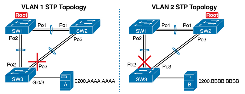
Figure P-5 VLAN Topology with PortChannels Between Switches
Example P-5 SW1 and SW2 MAC Tables with PortChannel Ports Listed
SW1# show mac address-table dynamic
          Mac Address Table
-------------------------------------------

Vlan    Mac Address       Type        Ports
----    -----------       --------    -----
  1     0200.AAAA.AAAA    DYNAMIC     Po2
  2     0200.BBBB.BBBB    DYNAMIC     Po1
SW2# show mac address-table dynamic
          Mac Address Table
-------------------------------------------

Vlan    Mac Address       Type        Ports
----    -----------       --------    -----
  1     0200.AAAA.AAAA    DYNAMIC     Po1
  2     0200.BBBB.BBBB    DYNAMIC     Po3
Switches use one of many load-balancing options to then choose the physical interface to use after matching MAC table entries like those shown in Example P-5. By default, Cisco Layer 2 switches often default to use a balancing method based on the source MAC address. In particular, the switch looks at the low-order bits of the source MAC address (which are on the far right of the MAC address in written form). This approach increases the chances that the balancing will be spread somewhat evenly based on the source MAC addresses in use.
Choosing the VLAN of Incoming Frames
To wrap up the analysis of switch data plane forwarding, this section mostly reviews topics already discussed, but it serves to emphasize some important points. The topic is simply this: How does a switch know which VLAN a frame is a part of as the frame enters a switch? You have seen all the information needed to answer this question already, but take the time to review.
First, some interfaces trunk, and in those cases, the frame arrives with a VLAN ID listed in the incoming trunking header. In other cases, the frame does not arrive with a trunking header, and the switch must look at local configuration. But because the switch will match both the destination MAC address and the frame VLAN ID when matching the MAC address table, knowing how the switch determines the VLAN ID is important.
The following list reviews and summarizes the key points of how a switch determines the VLAN ID to associate with an incoming frame:
Step 1. If the port is an access port, associate the frame with the configured access VLAN (switchport access vlan vlan_id).
Step 2. If the port is a voice port, or has both an IP Phone and PC (or other data device) connected to the phone:
A. Associate the frames from the data device with the configured access VLAN (as configured with the switchport access vlan vlan_id command).
B. Associate the frames from the phone with the VLAN ID in the 802.1Q header (as configured with the switchport voice vlan vlan_id command).
Step 3. If the port is a trunk, determine the frame’s tagged VLAN, or if there is no tag, use that incoming interface’s native VLAN ID (switchport trunk native vlan_id).
Troubleshooting VLANs and VLAN Trunks
A switch’s data plane forwarding processes depend in part on VLANs and VLAN trunking. Before a switch can forward frames in a particular VLAN, the switch must know about a VLAN and the VLAN must be active. And before a switch can forward a frame over a VLAN trunk, the trunk must currently allow that VLAN to pass over the trunk.
This final major section in this chapter focuses on VLAN and VLAN trunking issues, specifically issues that impact the frame switching process. The issues are as follows:
Step 1. Identify all access interfaces and their assigned access VLANs and reassign into the correct VLANs if incorrect.
Step 2. Determine whether the VLANs both exist (either configured or learned with the VLAN Trunking Protocol [VTP]) and are active on each switch. If not, configure and activate the VLANs to resolve problems as needed.
Step 3. Check the allowed VLAN lists, on the switches on both ends of the trunk, and ensure that the lists of allowed VLANs are the same.
Step 4. Check for incorrect configuration settings that result in one switch operating as a trunk, with the neighboring switch not operating as a trunk.
Step 5. Check the allowed VLANs on each trunk, to make sure that the trunk has not administratively removed a VLAN from being supported on a trunk.
Access VLAN Configuration Incorrect
To ensure that each access interface has been assigned to the correct VLAN, engineers simply need to determine which switch interfaces are access interfaces instead of trunk interfaces, determine the assigned access VLANs on each interface, and compare the information to the documentation. The show commands listed in Table P-1 can be particularly helpful in this process.
Table P-1 Commands That Can Find Access Ports and VLANs
EXEC Command |
Description |
|---|---|
show vlan brief show vlan |
Lists each VLAN and all interfaces assigned to that VLAN (but does not include operational trunks) |
show vlan id num |
Lists both access and trunk ports in the VLAN |
show interfaces type number switchport |
Identifies the interface’s access VLAN and voice VLAN, plus the configured and operational mode (access or trunk) |
show mac address-table |
Lists MAC table entries, including the associated VLAN |
If possible, start this step with the show vlan and show vlan brief commands, because they list all the known VLANs and the access interfaces assigned to each VLAN. Be aware, however, that these two commands do not list operational trunks. The output does list all other interfaces (those not currently trunking), no matter whether the interface is in a working or nonworking state.
If the show vlan and show interface switchport commands are not available in a particular exam question, the show mac address-table command can also help identify the access VLAN. This command lists the MAC address table, with each entry including a MAC address, interface, and VLAN ID. If the exam question implies that a switch interface connects to a single device, you should only see one MAC table entry that lists that particular access interface; the VLAN ID listed for that same entry identifies the access VLAN. (You cannot make such assumptions for trunking interfaces.)
After you determine the access interfaces and associated VLANs, if the interface is assigned to the wrong VLAN, use the switchport access vlan vlan-id interface subcommand to assign the correct VLAN ID.
Access VLANs Undefined or Disabled
Switches do not forward frames for VLANs that are (a) not known because the VLAN is not configured or has not been learned with VTP or (b) the VLAN is known, but it is disabled (shut down). This section summarizes the best ways to confirm that a switch knows that a particular VLAN exists, and if it exists, determines the shutdown state of the VLAN.
First, on the issue of whether a VLAN exists on a switch, a VLAN can be defined to a switch in two ways: using the vlan number global configuration command, or it can be learned from another switch using VTP. For this discussion, consider that the only way for a switch to know about a VLAN is to have a vlan command configured on the local switch.
Next, the show vlan command always lists all VLANs known to the switch, but the show running-config command does not. Switches configured as VTP servers and clients do not list the vlan commands in the running-config file nor the startup-config file; on these switches, you must use the show vlan command. Switches configured to use VTP transparent mode, or that disable VTP, list the vlan configuration commands in the configuration files. (Use the show vtp status command to learn the current VTP mode of a switch.)
After you determine that a VLAN does not exist on a switch, the problem might be that the VLAN simply needs to be configured.
Even for existing VLANs, you must also verify whether the VLAN is active. The show vlan command should list one of two VLAN state values, depending on the current state: either active or act/lshut. The second of these states means that the VLAN is shut down. Shutting down a VLAN disables the VLAN on that switch only, so that the switch will not forward frames in that VLAN.
Switch IOS gives you two similar configuration methods with which to disable (shutdown) and enable (no shutdown) a VLAN. Example P-6 shows how, first by using the global command [no] shutdown vlan number and then using the VLAN mode subcommand [no] shutdown. The example shows the global commands enabling and disabling VLANs 10 and 20, respectively, and using VLAN subcommands to enable and disable VLANs 30 and 40 (respectively).
Example P-6 Enabling and Disabling VLANs on a Switch
SW2# show vlan brief

VLAN Name                             Status    Ports
---- -------------------------------- --------- -------------------------------
1    default                          active    Fa0/1, Fa0/2, Fa0/3, Fa0/4
                                                Fa0/5, Fa0/6, Fa0/7, Fa0/8
                                                Fa0/9, Fa0/10, Fa0/11, Fa0/12
                                                Fa0/14, Fa0/15, Fa0/16, Fa0/17
                                                Fa0/18, Fa0/19, Fa0/20, Fa0/21
                                                Fa0/22, Fa0/23, Fa0/24, Gi0/1
10   VLAN0010                         act/lshut Fa0/13
20   VLAN0020                         active
30   VLAN0030                         act/lshut
40   VLAN0040                         active
SW2# configure terminal
Enter configuration commands, one per line.  End with CNTL/Z.
SW2(config)# no shutdown vlan 10
SW2(config)# shutdown vlan 20
SW2(config)# vlan 30
SW2(config-vlan)# no shutdown
SW2(config-vlan)# vlan 40
SW2(config-vlan)# shutdown
SW2(config-vlan)#
Mismatched Trunking Operational States
Trunking can be configured correctly so that both switches forward frames for the same set of VLANs. However, trunks can also be misconfigured, with a couple of different results. In some cases, both switches conclude that their interfaces do not trunk. In other cases, one switch believes that its interface is correctly trunking, while the other switch does not.
The most common incorrect configuration—which results in both switches not trunking—is a configuration that uses the switchport mode dynamic auto command on both switches on the link. The word “auto” just makes us all want to think that the link would trunk automatically, but this command is both automatic and passive. As a result, both switches passively wait on the other device on the link to begin negotiations.
With this particular incorrect configuration, the show interfaces switchport command on both switches confirms both the administrative state (auto) and the fact that both switches operate as “static access” ports. Example P-7 highlights those parts of the output from this command.
Example P-7 Operational Trunking State
SW2# show interfaces gigabit0/2 switchport
Name: Gi0/2
Switchport: Enabled
Administrative Mode: dynamic auto
Operational Mode: static access
Administrative Trunking Encapsulation: dot1q
Operational Trunking Encapsulation: native
! lines omitted for brevity
A different incorrect trunking configuration results in one switch with an operational state of “trunk,” while the other switch has an operational state of “static access.” When this combination of events happens, the interface works a little. The status on each end will be up/up or connected. Traffic in the native VLAN will actually cross the link successfully. However, traffic in all the rest of the VLANs will not cross the link.
Figure P-6 shows the incorrect configuration along with which side trunks and which does not. The side that trunks (SW1 in this case) enables trunking always, using the command switchport mode trunk. However, this command does not disable Dynamic Trunking Protocol (DTP) negotiations. To cause this particular problem, SW1 also disables DTP negotiation using the switchport nonegotiate command. SW2’s configuration also helps create the problem, by using a trunking option that relies on DTP. Because SW1 has disabled DTP, SW2’s DTP negotiations fail, and SW2 does not trunk.

Figure P-6 Mismatched Trunking Operational States
In this case, SW1 treats its G0/1 interface as a trunk, and SW2 treats its G0/2 interface as an access port (not a trunk). As shown in the figure at Step 1, SW1 could (for example) forward a frame in VLAN 10. However, SW2 would view any frame that arrives with an 802.1Q header as illegal, because SW2 treats its G0/2 port as an access port. So, SW2 discards any 802.1Q frames received on that port.
To deal with the possibility of this problem, always check the trunk’s operational state on both sides of the trunk. The best commands to check trunking-related facts are show interfaces trunk and show interfaces switchport.
Note
Frankly, in real life, just avoid this kind of configuration. However, the switches do not prevent you from making these types of mistakes, so you need to be ready.
Mismatched Supported VLAN List on Trunks
VLAN trunks on Cisco switches can forward traffic for all defined and active VLANs. However, a particular trunk may not forward traffic for a defined and active VLAN for a variety of other reasons. You should know how to identify which VLANs a particular trunk port currently supports, and the reasons why the switch might not be forwarding frames for a VLAN on that trunk port.
The first category in this step can be easily done using the show interfaces trunk command, which only lists information about currently operational trunks. The best place to begin with this command is the last section of output, which lists the VLANs whose traffic will be forwarded over the trunk. Any VLANs that make it to this final list of VLANs in the command output meet the following criteria:
The VLAN exists and is active on the local switch (as seen in the show vlan command).
The VLAN has not been removed from the allowed VLAN list on the trunk (as configured with the switchport trunk allowed vlan interface subcommand).
The VLAN has not been VTP-pruned from the trunk. (You can ignore this feature for the purposes of this book; it is mentioned here only because the show command mentions it.)
The trunk is in an STP forwarding state in that VLAN (as also seen in the show spanning-tree vlan vlan-id command).
Example P-8 shows a sample of the command output from the show interfaces trunk command, with the final section of the command output shaded. In this case, the trunk only forwards traffic in VLANs 1 and 4.
Example P-8 Allowed VLAN List and List of Active VLANs
SW1# show interfaces trunk

Port        Mode         Encapsulation  Status        Native vlan
Gi0/1       desirable    802.1q         trunking      1

Port        Vlans allowed on trunk
Gi0/1       1-2,P-4094

Port        Vlans allowed and active in management domain
Gi0/1       1,4

Port        Vlans in spanning tree forwarding state and not pruned
Gi0/1       1,4
The absence of a VLAN in this last part of the command’s output does not necessarily mean that a problem has occurred. In fact, a VLAN might be legitimately excluded from a trunk for any of the reasons in the list just before Example P-8. However, for a given exam question, it can be useful to know why traffic for a VLAN will not be forwarded over a trunk, and the details inside the output identify the specific reasons.
The output of the show interfaces trunk command creates three separate lists of VLANs, each under a separate heading. These three lists show a progression of reasons why a VLAN is not forwarded over a trunk. Table P-2 summarizes the headings that precede each list and the reasons why a switch chooses to include or not include a VLAN in each list.
Table P-2 VLAN Lists in the show interfaces trunk Command
List Position |
Heading |
Reasons |
|---|---|---|
First |
VLANs allowed |
VLANs 1–4094, minus those removed by the switchport trunk allowed command |
Second |
VLANs allowed and active… |
The first list, minus VLANs not defined to the local switch (that is, there is not a vlan global configuration command or the switch has not learned of the VLAN with VTP), and also minus those VLANs in shutdown mode |
Third |
VLANs in spanning tree… |
The second list, minus VLANs in an STP blocking state for that interface, and minus VLANs VTP pruned from that trunk |
Mismatched Native VLAN on a Trunk
Closing with a brief mention of one other trunking topic, you should also check a trunk’s native VLAN configuration at this step. Unfortunately, it is possible to set the native VLAN ID to different VLANs on either end of the trunk, using the switchport trunk native vlan vlan-id command. If the native VLANs differ according to the two neighboring switches, the switches will accidentally cause frames to leave one VLAN and enter another.
For example, if switch SW1 sends a frame using native VLAN 1 on an 802.1Q trunk, SW1 does not add a VLAN header, as is normal for the native VLAN. When switch SW2 receives the frame, noticing that no 802.1Q header exists, SW2 assumes that the frame is part of SW2’s configured native VLAN. If SW2 has been configured to think VLAN 2 is the native VLAN on that trunk, SW2 will try to forward the received frame into VLAN 2.