Chapter 9. Multisite Collaboration Solutions
This chapter covers the following topics:
![]() Dial Plan Elements: This topic will examine two specific elements of a Cisco Expressway dial plan; Zones and Search Rules.
Dial Plan Elements: This topic will examine two specific elements of a Cisco Expressway dial plan; Zones and Search Rules.
![]() Simple Video Network with a Flat Dial Plan: This topic will examine the advantages and disadvantages of a simple video network with a flat dial plan.
Simple Video Network with a Flat Dial Plan: This topic will examine the advantages and disadvantages of a simple video network with a flat dial plan.
![]() Complex Video Network with a Flat Dial Plan: This topic will examine the advantages and disadvantages of a complex video network with a flat dial plan.
Complex Video Network with a Flat Dial Plan: This topic will examine the advantages and disadvantages of a complex video network with a flat dial plan.
![]() Complex Video Network with a Structured Dial Plan: This topic will examine the advantages and disadvantages of a complex video network with a structured dial plan.
Complex Video Network with a Structured Dial Plan: This topic will examine the advantages and disadvantages of a complex video network with a structured dial plan.
![]() Hierarchical Video Network with a Structured Dial Plan: This topic will examine the advantages and disadvantages of a hierarchical video network with a structured dial plan.
Hierarchical Video Network with a Structured Dial Plan: This topic will examine the advantages and disadvantages of a hierarchical video network with a structured dial plan.
![]() Configuring Neighbor Zones: This topic will explain how to deploy Neighbor Zones and Search Rules on an Expressway Core between two Expressway Cores and between an Expressway Core and Cisco Unified CM.
Configuring Neighbor Zones: This topic will explain how to deploy Neighbor Zones and Search Rules on an Expressway Core between two Expressway Cores and between an Expressway Core and Cisco Unified CM.
All the elements discussed in the previous two chapters are components of the Call Processing Order. After the per-search components are exhausted, the next successive function is to search Zones. There are a lot of different Zones that can be configured within the Cisco Expressway. The order these Zones should be searched, and how they are search requires more explanation than one chapter can contain. Therefore, this chapter will examine Zones as whole, and then focus on Neighbor Zones specifically.
This chapter covers the following objectives from the Implementing Cisco Collaboration Cloud and Edge Solutions (CLCEI) exam 300-820:
![]() 1.7.c Describe Expressway Core dial plan elements: Zones
1.7.c Describe Expressway Core dial plan elements: Zones
![]() 2.2.c Configure Expressway Core Dial Plan Elements: Zones
2.2.c Configure Expressway Core Dial Plan Elements: Zones
![]() 2.4.d Configure a Business to Business (B2B) Collaboration Solution: Neighbor Zones
2.4.d Configure a Business to Business (B2B) Collaboration Solution: Neighbor Zones
![]() 2.4.g Configure a Business to Business (B2B) Collaboration Solution: SIP trunk integration with Cisco Unified Communications Manager
2.4.g Configure a Business to Business (B2B) Collaboration Solution: SIP trunk integration with Cisco Unified Communications Manager
“Do I Know This Already?” Quiz
The “Do I Know This Already?” quiz allows you to assess whether you should read this entire chapter thoroughly or jump to the “Exam Preparation Tasks” section. If you are in doubt about your answers to these questions or your own assessment of your knowledge of the topics, read the entire chapter. Table 9-1 lists the major headings in this chapter and their corresponding “Do I Know This Already?” quiz questions. You can find the answers in Appendix A, “Answers to the ‘Do I Know This Already?’ Quizzes.”
Table 9-1 ”Do I Know This Already?” Section-to-Question Mapping

Caution
The goal of self-assessment is to gauge your mastery of the topics in this chapter. If you do not know the answer to a question or are only partially sure of the answer, you should mark that question as wrong for purposes of the self-assessment. Giving yourself credit for an answer you correctly guess skews your self-assessment results and might provide you with a false sense of security.
1. Which of the following is a Zone type on the Cisco Expressway?
a. MGCP Zone
b. SIP Zone
c. H.323 Zone
d. Neighbor Zone
e. Transversal Zone
2. Which of the following is the correct way to set up the Incoming calls to unknown IP addresses setting on the Cisco Expressway?
a. Expressway Core should be set to Indirect while the Expressway Edge is set to Direct
b. Expressway Core should be set to Direct and the Expressway Edge is set to Direct
c. Expressway Core should be set to Indirect and the Expressway Edge is set to Indirect
d. Expressway Core should be set to Direct while the Expressway Edge is set to Indirect
3. How are zones searched on the Cisco Expressway?
a. Zones are searched by type. The order they are searched are Local Zone, first and DNS Zone last.
b. Zones are searched by the order Search Rules are listed in the Cisco Expressway.
c. Zones are search by priority, and the larger the number the higher the priority.
d. Zones are search by priority, and the smaller the number the higher the priority.
4. In which of the following scenarios are media and signaling required to move through the Cisco Expressway?
a. SIP to SIP calls
b. SIP to H.323 calls
c. H.323 to H.323 calls
d. All calls require signaling and media to move through the Cisco Expressway.
e. Call Setup signaling always goes through the Cisco Expressway, but media is always point-to-point.
5. What component is used in Call loop detection mode to prevent loop backs from occurring?
a. Call Signaling Optimization
b. Call Serial Number
c. Call Tag
d. Destination endpoint alias
6. What is the main distinguishing factor of a complex video network with a structured dial plan on an Expressway?
a. Unique suffixes
b. Site Codes
c. Unique Prefixes
d. Unique Aliases
7. What setting should be used on the Cisco Expressway when more than two Expressways are being used in a video network in order to limit the number of hops for call setup signaling?
a. Call loop detection mode
b. Call signaling optimization
c. Optimal call routing
d. Neighbor Zone
8. Which of the following is an appropriate used for Neighbor Zones?
a. Neighboring a CUCM to an Expressway Core
b. Neighboring an Expressway Core to an Expressway Edge
c. Neighboring an Expressway Edge to an Expressway Edge
d. Neighboring an Expressway Edge to a DNS server
9. While creating a Neighbor Zone from an Expressway Core to another Expressway Core, the engineer decides to change the SIP Transport to TLS. What should he change the SIP port to so that TLS can be used over the appropriate port?
a. 5060
b. 5061
c. 5062
d. The port will change automatically when the Transport setting is changed.
10. An Engineer just finished building a Neighbor Zone on the Expressway Core to the CUCM, but the Zone is showing as inactive. Which of the following is most likely the cause of this issue?
a. The CUCM needs a SIP Trunk to the Expressway Core before the Neighbor Zone will become active
b. The wrong port is being used for SIP on the Neighbor Zone
c. H.323 was not disabled before creating the Zone
d. The wrong peer address was entered for the Expressway
Foundation Topics
Dial Plan Elements
The call processing order, which has been discussed extensively in previous chapters, is such an important process to understand. It affects every call through the Cisco Expressway. Knowing all the components involved with the call processing order as well as understanding how they work will help administrators troubleshoot calling issues when they arise within the Cisco Expressway.
As you should know by now, the call processing order begins with the pre-search components. When a call request enters the Cisco Expressway, it will first check the alias dialed against Transforms, Call Policy and User Policy. Once the pre-search components have all been checked, the next step in the call processing order is to perform a Zone search in order to locate the destination alias. The first Zone that should be searched is the Local Zone. If a match is not found, then external Zones should be searched. Zones are pointers or trunks to other servers, and there are several types of external Zones that exist. Search Rules determine what order Zones are searched within the Cisco Expressway.
Zones
Chapter 6, “Registration on Cisco Expressway,” introduced the logical components that make up the Cisco Expressway. Within that chapter the Local Zone was defined as the Expressway itself. So, when the Local Zone is searched, what the Expressway is actually searching for are endpoints registered locally to that Cisco Expressway. Since endpoints register to Subzones it is logical to think of a Local Zone search as a search within the Subzones.

Beyond the Local Zone additional Zones can be configured and used on Expressways to establish communication with other servers and organizations outside the corporate network. Other Zones that exist within the Cisco Expressway include the Default Zone, Neighbor Zones, Traversal Zones and DNS and ENUM Zones.
As defined in Chapter 6, the Default Zone is the default path into and out from the Local Zone. It always exists on the Expressway and cannot be deleted. The Default Zone is used for sending call media out from the Local Zone and receiving call media into the Local Zone after external destinations have been established using other Zones. It is also used for broadcast traffic if the appropriate zone has not been configured. An example of the type of broadcast traffic that’s sent would be calls to unknown IP addresses. This type of call is not allowed by default on the Cisco Expressway. However, if this setting is enabled, and appropriate search rules are created, then the Default Zone can be used to send a broadcast communication throughout the broadcast domain of the network to locate an unknown IP address. Figure 9-1 illustrates how calls to unknow IP addresses works in a Cisco Expressway environment.
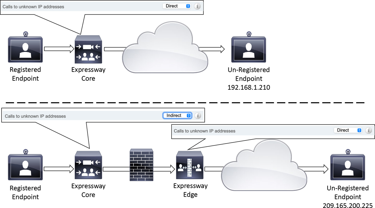
Figure 9-1 Calls to Unknown IP Addresses Operation
In the top illustration of Figure 9-1 the Expressway Core has the Calls to Unknown IP addresses setting set to Direct. This allows the Expressway to send a broadcast search out the Default Zone to locate the endpoint that is not registered. The Expressway Core should only have the Calls to Unknown IP addresses setting set to Direct if the unregistered endpoint exists within the same broadcast network. However, this is almost never the case. In most cases a call to an unknown IP address exists outside a corporate network and therefore is not within the local broadcast domain.
In this type of scenario, the Calls to unknown IP addresses setting on the Expressway core should be set to Indirect. This will allow the Expressway Core to forward the call request across the Traversal Zone to the Expressway Edge. The Calls to unknown IP addresses setting on the Expressway Edge should then be set to Direct. This will allow the call to traverse through the firewall in order to connect to the endpoint that exists outside the corporate network. The Calls to unknown IP addresses setting can be configured in the Cisco Expressway by navigating to Configuration > Dial plan > Configuration.
Incoming calls using IP addresses can also be allowed by using the Expressway IP address. However, an alias should be included with the dialed alias, such as [email protected] or [email protected] assuming the IP address in both these examples is the IP address of the Expressway. In the event that an incoming call to the Expressway IP address does not include a callee alias, a fallback alias can be configured in the Expressway. This alias will be used to forward all incoming calls that used only the Expressway IP address. Figure 9-2 illustrates the dial plan configuration page on the Cisco Expressway.
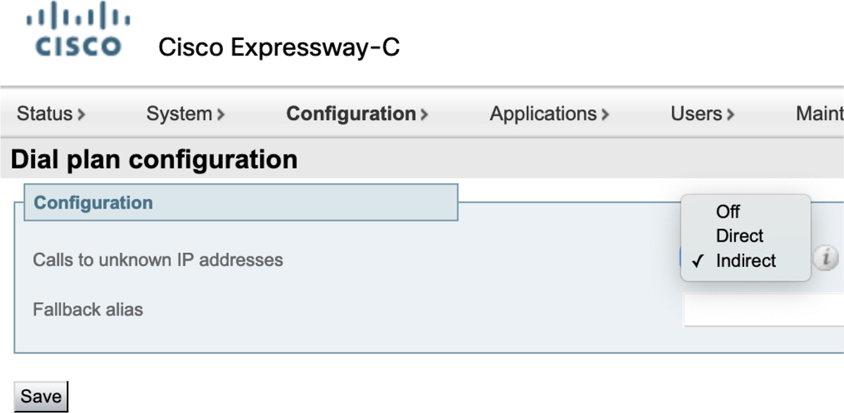
Figure 9-2 Dial Plan Configuration Menu on Cisco Expressway
Another Zone type on the Cisco Expressway is Neighbor Zones, which is used to communicate with other communication servers within the same LAN or WAN. These servers could include other Cisco Expressway Cores, Cisco Unified CMs, Cisco Meeting Servers, a Microsoft unified communications server or some other third-party gatekeeper or SIP server. Since the rest of this chapter will delve into Neighbor Zones with more depth, I will save this discussion till later.
Traversal Zones are used for communication through a Firewall. Two Expressways are required to set up a traversal communication. The Expressway Core needs to be located inside the firewall, while the Expressway Edge needs to be located outside firewall. The Expressway Core supports a Traversal Client Zone, while the Expressway Edge can support both a Traversal Client Zone and a Traversal Server Zone. The Client Zone must communicate with the Server Zone to establish a traversal connection. Another type of Traversal Zone that exists within the Cisco Expressway is Unified Communications Traversal Zone. This type of Traversal Zone is only used on conjunction with a Mobile Remote Access deployment, which will be discussed more in Part 3 of this book. There are two Communication protocols that can be used with the Firewall Traversal Solution. Assent is a Cisco proprietary protocol that support both SIP and H.323 communication. H.460.18 and H.460.19 are ITU standards only used for H.323 firewall traversal communication.
DNS Zones are used for communication between the Expressway and a Domain Name Server (DNS). Appropriate service records (SRV) and A-records need to be set up in DNS for routing to be established between communication servers. ENUM (Enumerated Dialing) can also be used for routing calls between E.164 aliases and URIs. An ENUM Server can be built in any DNS Server or can be configured as a separate entity.
Cisco introduced a new type of DNS Zone on the Cisco Expressway Edge servers called the Webex Zone beginning in version X8.11.4. The Webex Zone not only automates and simplifies Hybrid Call Service configuration, but it is also a single zone entry that ensures that all calling and meetings solutions under the Webex banner precisely route to the correct cloud microservices and are handled accordingly.
The decision-making for call routing and protocols is offloaded from the Expressway itself (manual configuration by you, the admin) onto DNS (automated configuration, managed by Cisco). The decisions are made by a Name Authority Pointer (NAPTR) DNS record that is able to pinpoint call and meeting paths that are then advertised to the DNS SRV record. The two entries in ANSWER SECTION determine the SRV lookup that gets advertised back to the Expressway-E. The Expressway-E then does the SRV lookup as usual. Example 9-1 illustrates the NAPTR lookup made by the Expressway through a public DNS.
Example 9-1 Webex NAPTR DNS Lookup from Cisco Expressway
;; ANSWER SECTION:
example.call.ciscospark.com. 300 INNAPTR 50 50 “S” “SIPS+D2T” ““
_sips._tcp.call.ciscospark.com.
example.call.ciscospark.com. 300 INNAPTR 30 50 “S” “SIPSM+D2T” ““
_sips._tcp.callservice.ciscospark.com.
All of this happens behind the scenes, and all you have to do is create the Webex Zone on Expressway with preconfigured settings; no further zones-per-service are required. A further benefit is that your deployment is future-proofed as more services are added to Cisco’s Webex cloud and more complex routing decisions need to be made.
Search Rules
For all zone types including the Local Zone, Search Rules must be configured before any calls can be routed. Search Rules can be created to search Any Alias, Any IP Address, or can perform a search based on an Alias Pattern Match. This last option allows patterns to be configured based on Exact Match, Prefix, Suffix or Regex. The previous section mentioned that Calls to unknown IP addresses must have the setting configured as Direct or Indirect and have the appropriate rules configured. In addition to changing the Calls to unknown IP addresses setting, a search rule must be configured to allow Any IP address calling. If the Expressway Core has been configured as Indirect, then the Any IP address rule should point to the appropriate Traversal Zone. If the Expressway Edge has been configured as Direct, then the Any IP address rule should point to the Local Zone. From there the call will find its way out the Default Zone because of the Calls to unknown IP addresses setting.
Zones are searched based on the priority of the Search Rules. Priority values can be set between 1 and 65,534. 1 is the highest priority, so the larger the number the lower the priority. The first zone that should be searched is the Local Zone. Therefore, there is a default Search Rule that comes preconfigured on the Expressway with a priority of 50 that matches Any alias and points to the Local Zone. This rule can be modified, changed, inactivated or deleted if needed. When the Expressway searches a rule for an alias pattern match and that alias is not found, the Expressway will proceed to search all the applicable rules for all zones based on this priority until a match is found or all available options have been exhausted. Since there are different types of zones available on the Cisco Expressway, there is a preferred search order of these zones that should be followed. Understand that this is not a hard-fast rule, and different circumstances may determine following a different search order of zones. Best practice suggests that the Neighbor Zones are searched after the Local Zone, followed by Traversal Zones, and last the DNS/ENUM Zones should be searched. A suggested way of grouping the priorities to create this manner of searches could be as follows:
Local Zone: 1-19,999
Neighbor Zone: 20,000-29,999
Traversal Zone: 30,000-39,999
DNS and ENUM Zones: 40,000-49,999
Webex Zone: 50,000-59999
The actual priority values used do not matter so long as you keep in mind that smaller numbers are searched first, and bigger numbers are searched last. Each administrator should adjust priority-groupings based on enterprise needs. There are some other settings that are less commonly used when configuring Search Rules on an Expressway, but they do warrant a brief explanation.
![]() Rule Name is simply the name given to a rule. It is important to provide a name that describes the purpose of the rule.
Rule Name is simply the name given to a rule. It is important to provide a name that describes the purpose of the rule.
![]() Description is an optional setting that can be used to better describe the purpose of a rule. This allows administrators to keep rule names shorter and put to longer details in the description.
Description is an optional setting that can be used to better describe the purpose of a rule. This allows administrators to keep rule names shorter and put to longer details in the description.
![]() The Protocol setting allows the administration to specify a protocol with which this rule can be used. If SIP were selected, then H.323 calls could not use this Search Rule. The default value is Any, and it can be changed to SIP or H.323.
The Protocol setting allows the administration to specify a protocol with which this rule can be used. If SIP were selected, then H.323 calls could not use this Search Rule. The default value is Any, and it can be changed to SIP or H.323.
![]() The Source setting determined the zone from which a call must originate. Options include Any, All zones, Local Zone and Named.
The Source setting determined the zone from which a call must originate. Options include Any, All zones, Local Zone and Named.
![]() Any: Locally registered devices, neighbor or traversal zones, and any non-registered devices.
Any: Locally registered devices, neighbor or traversal zones, and any non-registered devices.
![]() All zones: Locally registered devices plus neighbor or traversal zones.
All zones: Locally registered devices plus neighbor or traversal zones.
![]() Local Zone: Locally registered devices only.
Local Zone: Locally registered devices only.
![]() Named: A specific zone or subzone. A dropdown menu is presented with all available options should the Named setting be selected.
Named: A specific zone or subzone. A dropdown menu is presented with all available options should the Named setting be selected.
![]() Request must be authenticated indicates whether this search rule applies only to authenticated search requests. The default value is No.
Request must be authenticated indicates whether this search rule applies only to authenticated search requests. The default value is No.
![]() Mode describes the pattern used to match a destination alias as described previously. Mode can be set to Any alias, Any IP address or Alias pattern match. When Alias pattern match is selected, three additional fields appear.
Mode describes the pattern used to match a destination alias as described previously. Mode can be set to Any alias, Any IP address or Alias pattern match. When Alias pattern match is selected, three additional fields appear.
![]() Pattern type can be set to Exact, Prefix, Suffix or Regex.
Pattern type can be set to Exact, Prefix, Suffix or Regex.
![]() Pattern string is the pattern that should be matched based on the pattern type selected previously.
Pattern string is the pattern that should be matched based on the pattern type selected previously.
![]() Pattern behavior determines what the Expressway should do with alias once a match has been made. The Pattern behavior options include:
Pattern behavior determines what the Expressway should do with alias once a match has been made. The Pattern behavior options include:
• Strip: Commonly used with the prefix or suffix pattern type, this behavior will remove whatever pattern string was matched.
• Leave: Commonly used with exact match, however any of the pattern types could be used here. The alias that was matched by this pattern will be searched for in its exact form.
• Replace: This behavior will open another configuration option where a Replace string can be entered. This new string will be used to try and locate the destination endpoint. This one is most commonly used with Regex, but can be used with Prefix or Suffix too.
![]() On successful match is a behavior that determines if the Expressway should continue to search for alternative paths to a destination should a match be found. If no match is found the Expressway will continue the search regardless how this setting is configured. The two configuration options include Continue or Stop. Using the Stop option helps to prevent loopback issues when searching external zones.
On successful match is a behavior that determines if the Expressway should continue to search for alternative paths to a destination should a match be found. If no match is found the Expressway will continue the search regardless how this setting is configured. The two configuration options include Continue or Stop. Using the Stop option helps to prevent loopback issues when searching external zones.
![]() Target is the destination zone the call will be forwarded to when the Expressway finds a successful match. Local Zone is always one of the options, although any additional zones that have been created with be listed as viable options as well.
Target is the destination zone the call will be forwarded to when the Expressway finds a successful match. Local Zone is always one of the options, although any additional zones that have been created with be listed as viable options as well.
![]() State is the last settings that determines is this Search Rule is active or inactive. This setting can be configured as Enabled or Disabled. Disabling a rule is better than deleting the rule in case a time comes when this rule should be used again. This will prevent having to re-create the rule. Disabling a rule also helps in isolating issues while troubleshooting calls.
State is the last settings that determines is this Search Rule is active or inactive. This setting can be configured as Enabled or Disabled. Disabling a rule is better than deleting the rule in case a time comes when this rule should be used again. This will prevent having to re-create the rule. Disabling a rule also helps in isolating issues while troubleshooting calls.
It is important to note that if the Expressway changes an alias using the mechanisms under Mode, then the changes will only be applied for the search under this particular Search Rule. If a match is not found, then the alias will revert back to the state in which it existed prior to this search. Figure 9-3 illustrates these menus for a Search Rule in the Cisco Expressway.
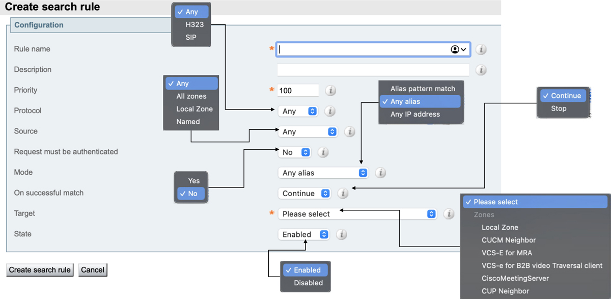
Figure 9-3 Search Rule Menu Options
Simple Video Network with a Flat Dial Plan
There are four different deployment models that can be used in a Cisco Expressway architectural design. Each of these models have merits and limitations, and there are circumstances that would warrant using each of these models depending on the customer environment. Up to this point in the book only one of these deployment models has been discussed, which is the simple video network with a flat dial plan. A single Expressway Core is used, and all signaling and media traffic is linked through that one Expressway. Each endpoint is using a unique alias and registers to the single Expressway; therefore, no neighboring is required between Expressway Core peers. If a simple video network with a flat dial plan model is used for a company that spans multiple locations linked across a WAN, then subzones can be used to represent each physical location respectively. A simple video network with a flat dial plan could involve a single cluster of Expressway Cores and could also involve an Expressway Edge for firewall traversal calls or MRA. Figure 9-4 illustrates a single combined deployment model that supports four locations interconnected across a WAN.

Figure 9-4 Simple Video Network with a Flat Dial Plan
There are some advantages and disadvantages to using the Simple Video network with a flat dial plan. The advantages to this type of deployment model are that it is a simple concept to configure and a simple model to maintain. This is an ideal model for a customer environment that only has one location, or only a few endpoints spread out across multiple locations, as illustrated in Figure 9-4.
On the other side of the coin there are many disadvantages to this type of deployment model. All signaling and media traffic is linked through the same Expressway, so if that Expressway ceases to function, no calls are possible. This single point of failure can be overcome by implementing a cluster of Expressways, but there is still another limitation to funneling all the media and signaling through a single location.
When a non-traversal call is set up through the Cisco Expressway the signaling for call setup must travel through the expressway before it is sent to the destination endpoint. However, the actual UDP media and signaling for the audio and video are direct between the endpoints. This works well in this scenario since bandwidth will only be consumed at the locations involved with the call. This is true so long as the call is not a traversal call. With traversal calls the media must always traverse through the Expressway. As mentioned in Chapter 3, “Initial Configuration Settings on Expressway,” there are four types of traversal calls the Cisco Expressway supports. They are Firewall Traversal, SIP/H.323 Interworking, IPv4/Ipv6 Interworking, and Dual Network Traversal. The last one is only available on the Expressway Edge server. In the illustration of Figure 9-4, if an H.323 endpoint in Raleigh is trying to communicate with a SIP endpoint in Sydney, the media must travel through San Jose. Therefore, bandwidth at the San Jose site must be robust enough to support calls at all locations simultaneously, including San Jose itself. This could potentially create an issue with other calls connecting, even if they are not traversal calls. If the hosting site of San Jose runs out of bandwidth, signaling for call setup will not even get through this site. This is why this type of deployment model is not suitable for medium or large sized organizations.
Complex Video Network with a Flat Dial Plan
As companies grow the need for larger networks becomes inevitable. A simple means of scaling a network would be to add expressways to each location. This creates a complex video network with a flat dial plan that would definitely overcome the limitations of the previously described deployment model.
This deployment model is complex for two main reasons. There are now more than one Expressway that needs to be managed, and communication between the two or more Expressways needs to be established and maintained. However, the dial plan doesn’t change. You can continue to use the same flat dial plan that was used in the previous deployment model. Assume the same customer represented in the previous figure were to simply add an Expressway Core to each location, and then neighbor the Expressways together using Neighbor Zones. Because this model uses a flat dial plan, the Any Alias Search Rule could be used for each Neighbor Zone created. When an Expressway receives a call for an endpoint that is not registered locally, it will send out a Location Request (LRQ) to all the other Expressways it is neighbored to where there is a matching Search Rule. Figure 9-5 illustrates how this complex video network with a flat dial plan might look.
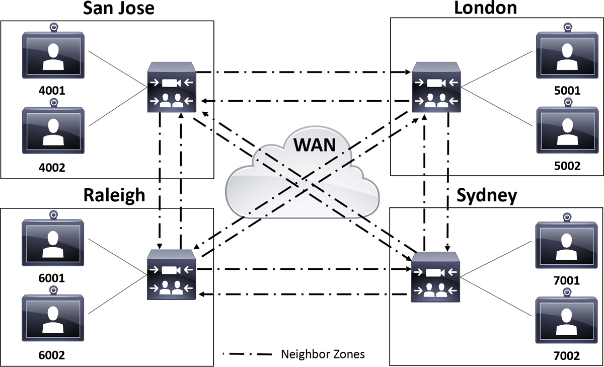
Figure 9-5 Complex Video Network with a Flat Dial Plan
There are several advantages to this type of deployment model. Even though it is called a complex video network, it is still a pretty simple concept to configure and maintain. So, the advantage of the simple video network holds true for this video network design as well. Additionally, the disadvantages of the simple video network become advantages within the complex video network model. Each Expressway is neighbored to all other Expressways in a full mesh model. Therefore, there are three Neighbor Zones on each respective Expressway. Any calls between locations will only consume bandwidth within the involved locations regardless of the type of call, traversal or non-traversal. There is no longer a single point of failure either. If the Expressway in San Jose fails, calls are still possible between the other three locations.
Unfortunately, this deployment model is not impervious to disadvantages. All Expressways must know about all other peers. This means that this is not a very scalable solution. Adding or removing an Expressway requires changing the configuration of every Expressway. Already, there are three Neighbor Zones on each Expressway. If I were to add a location in Paris, then I would have to create four Neighbor Zones on the Paris Expressway plus one additional Neighbor Zone on each of the existing Expressways. That’s eight Neighbor Zones, plus corresponding Search Rules, that must be created just to add one location. Then for each location added after that the number of Neighbor Zones grows exponentially. This is definitely not a very scalable deployment model.
Another disadvantage is that one call attempt can result in many location-requests being sent out. As mentioned previously, when calling an endpoint that is not registered on the same local Expressway, a Location Request (LRQ) will be sent to every Expressway with a matching Search Rule. Since this deployment model uses a flat dial plan, all the Search Rules use the Any Alias pattern match. This will result in an external LRQ going out to every neighbored Expressway. This can create a call routing error called Loop Back, which will result in the call failing. Figure 9-6 illustrates how loops can occur in a full-mesh topology between Expressways.

Figure 9-6 Loop Back Issues
In Figure 9-6 Endpoint 4001 in San Jose is attempting to call endpoint 7002 in Sydney. Since the alias 7002 is not registered to the San Jose Expressway, the Expressway sends out an LRQ to London, Raleigh and Sydney Expressways. Following the logical path, the Sydney Expressway identifies the endpoint registered locally and will reply with a Location Confirm (LCF). However, there are still two more searches out that must complete their cycle.
Since the destination endpoint is not found in Raleigh, that Expressway will send out its own set of LRQs to try and locate the endpoint. Since the request originated from San Jose, the Raleigh Expressway will not send an LRQ back to the San Jose Expressway. However, it will send an LRQ to London and Sydney Expressways. Likewise, the London Expressway will continue the search from the San Jose LRQ by sending its own LRQ to Raleigh and Sydney. This is where the issue begins to propagate. Neither Raleigh nor London sent an LRQ back to San Jose from the original LRQ sent to these locations. However, Raleigh will send the LRQ from London to San Jose and Sydney. Likewise, London will send the LRQ from Raleigh to San Jose and Sydney. Even though the endpoint was located in Sydney, the call will fail because the San Jose Expressway received a loop back LRQ on the original request it sent out.
There is a setting on the Cisco Expressway called Call loop detection mode that prevents search loops occurring. Each search has a call serial number and a call tag. The serial number is unique to the search, but the tag information is passed with a location request. The Expressway uses the tag to identify a call that has already been received and hence ignored, preventing loop back errors. This is not a full proof prevention from loop backs from occurring. However, customers to whom it makes the most since to use a complex video network with a flat dial plan can still be protected from being crippled from this loop back issue. Figure 9-7 illustrates the Loop Detection settings on the Cisco Expressway.

Figure 9-7 Cisco Expressway Loop Detection
Complex Video Network with a Structured Dial Plan
Since the Call loop detection mode setting does not always work to prevent loop backs, there is another deployment model that can be used as a full proof method preventing loop backs. The complex video network with a structured dial plan introduces a more complex and structured dial plan allowing Search Rules to target specific locations based on the alias patterns that are matched. Figure 9-8 illustrates how a complex video network with a structured dial plan can be configured.
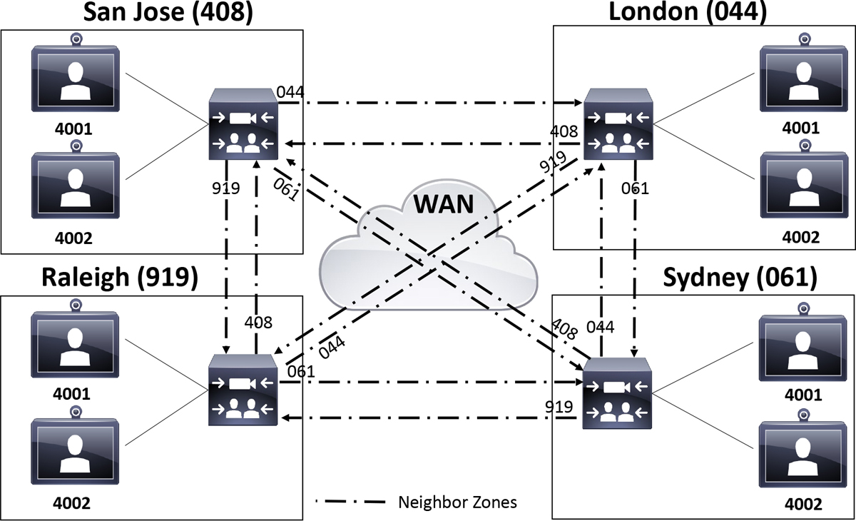
Figure 9-8 Complex Video Network with a Structured Dial Plan
In the previous figure, notice first that all the endpoints use the same four-digit numbers as their local extensions regardless of their location. In a production environment it would not be necessary to use the same numbers on all endpoints. It is only done in this figure to illustrate that the structure of this dial plan allows for this type of overlap in extensions. This in turn allows for up to 10,000 phones to be supported within each location while still using four-digit extensions. Using the flat dial plan exemplified in previous figures, only 1000 phones could be supported per location using a four-digit extension.
The real key to this structured dial plan is the use of a site code of sorts. These are not “Site Codes” like you would configure on the CUCM. The Search Rules that would coincide with Figure 9-8 would actually use a prefix pattern match. A suffix could also be used for domain routing, if SIP URIs are being used as the alias type without a numeric host portion of the URI. In the case of this figure, a site code, or prefix, is assigned to each location. San Jose is 408, London is 044, Raleigh is 919 and Sydney is 061. These prefixes are not configured on the Expressways for the site they are assigned to. Rather, the Search Rules on the other three Expressways are configured with the prefix of the fourth Expressway. For example, a Search Rule on the London Expressway will be configured with the 408 prefix and applied to the San Jose Neighbor Zone. The default Any Alias rule for the Local Zone could be changed to use a regular expression that allowed local dialing to include the London prefix or not. That regular expression would look something like this:
(044)?d{4}
The (044)? Indicates that the dialed number can start with 044, or not. The d{4} indicates there must be four numbers at least in this pattern match. If any endpoint in London dials 4084002 the call will only be routed to San Jose. It will not search the Local Zone, nor will it send an LRQ to Raleigh or Sidney. In this manner, the structure of this dial plan will prevent loop back errors from occurring. This is the greatest advantage of the complex video network with a structured dial plan.
Since this is still a complex video network, however, this solution still possesses most of the disadvantages the Complex Video network with a flat dial plan contained. The greatest disadvantage is the lack of scalability. The complexity of this solution grows exponentially as each additional location with an Expressway is added.
Hierarchical Video Network with a Structured Dial Plan
The scalability issue of the previous two deployment models is resolved in the hierarchical video network with a structured dial plan. There is no need to neighbor all the Expressways with each other in a full mesh pattern. One Expressway is nominated as the directory Expressway for the hierarchical deployment. The “directory” designation is in name only based on the network positioning and function this Expressway will serve. No actual settings or licensing determines if an Expressway is the directory Expressway or not. Each additional Expressway is neighbored to that directory Expressway, and the structured dial plan on the directory Expressway determines how calls are routed. Different directory Expressways can also serve as sub-directory Expressways by using a global directory Expressway between them. Figure 9-9 illustrates a hierarchical video network with a structured dial plan that uses a global directory Expressway with regional sub-directory Expressways.
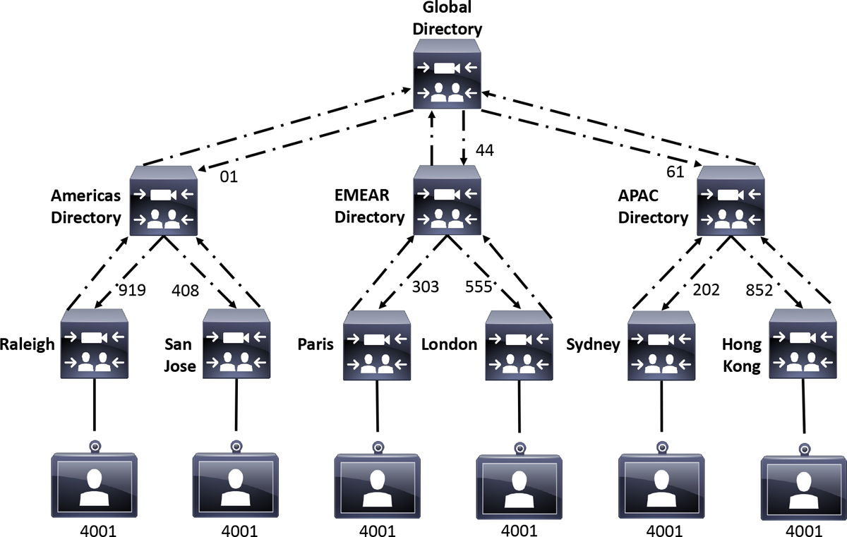
Figure 9-9 Hierarchical Video Network with a Structured Dial Plan
Obviously, this type of video network design would be best suited for a large enterprise corporation with a wide footprint that spans multiple locations. Each location possesses its own Expressway that can support the local registration of endpoints. In the example provided in Figure 9-9, There are three geographical regions, each represented with an Expressway acting as the directory for that region. The local Expressway for each location is neighbored to the regional directory Expressway and vice versa. Each regional directory Expressway is also neighbored to a global directory Expressway, and vice versa, so that communication can be shared globally. A structured dial plan accompanies this design so that loop backs can be avoided, and calls can be routed quickly and easily between endpoints located in different locations.
As with each of the deployment models discussed previously, there are certain advantages and disadvantages to this model. I mentioned the first of these advantages at the beginning of this section. The hierarchical video network with a structured dial plan resolves the scalability issue of the complex video network designs. Adding a location only requires building two neighbor zones with corresponding search rules. Using the example in Figure 9-9, if I wanted to add a location in Los Angeles, I would need to build a neighbor zone between the LA Expressway and the Americas Directory Expressway and vice versa. Now any endpoint from any location can call to an endpoint in LA and an LA endpoint can call to any endpoint at any other location. I can add a location in Berlin Germany, and I only need to create two Neighbor Zones and corresponding search rules. I can add a location in Tokyo Japan and I only need to create two Neighbor Zones and corresponding search rules. This deployment model is very scalable, only requiring the same minimum effort to add an unlimited number of locations each time.
Another series of advantages to the hierarchical video network with a structured dial plan are closely related to the scalability advantage.
![]() No fully connected mesh of Expressways is required. All local Expressways do not need to know all other Expressways. Each Expressway only needs to know how to reach its own directory Expressway.
No fully connected mesh of Expressways is required. All local Expressways do not need to know all other Expressways. Each Expressway only needs to know how to reach its own directory Expressway.
![]() A minimized number of LRQs need to be issued when a call is attempted.
A minimized number of LRQs need to be issued when a call is attempted.
![]() Calls will only consume BW within the local Expressway locations.
Calls will only consume BW within the local Expressway locations.
The reason these advantages exist and are all so closely related has to do with a function of the Cisco Expressways called Optimal Call Routing, which should be used anytime more than one Expressway is used. Figure 9-10 illustrates how Optimal Call Routing operates.

Figure 9-10 Optimal Call Routing Operation
In the previous figure, the Raleigh Expressway is neighbored to the Americas Expressway, The Americas Expressway is neighbored to the Raleigh and San Jose Expressways, and the San Jose Expressway is neighbored to the Americas Expressway. There is no Neighbor Zone between the Raleigh and San Jose Expressways. The Raleigh endpoint on the left side of the figure tries to call the San Jose endpoint on the right side of the figure by dialing 4084001. When the call request reaches the Raleigh Expressway, no match is found locally, so this Expressway will send an LRQ to its neighbor, the Americas Directory Expressway. The Americas Directory Expressway cannot locate the endpoint locally either, so the LRQ is forwarded to the San Jose Expressway. Since the San Jose Expressway can locate the endpoint locally, it will respond to the Americas Directory Expressway with a Location Confirm (LCF) that includes the IP address of the Expressway the endpoint is registered to. The Americas Directory Expressway will then send the LCF to the Raleigh Expressway with the destination IP address of the San Jose Endpoint. The Raleigh Expressway and the San Jose Expressway can now communicate directly with one another to send the rest of the call setup messaging without involving the Americas Directory Expressway in the rest of the call. So long as the call is not a traversal call, the media can be direct between the Raleigh endpoint and the San Jose Endpoint. Only the Raleigh and San Jose Expressways will consume a call license. Optimal call routing prevents calls being passed through more Expressways and consuming more licenses than is needed.
Optimal Call Routing can be configured the same way Call loop detection mode is configured, because these settings are under the same menu on the Cisco Expressway. However, the setting for Optimal Call Routing is called Call signaling optimization. Just remember that Call signaling optimization is the setting on a Cisco Expressway that allows for Optimal Call Routing. Optimal Call Routing is the function of limiting hops between Expressways for call setup signaling when more than two Expressways are being used in a video network. On the Cisco Expressway web interface, navigate to Configuration > Call routing. Change the Call signaling optimization settings to On and click Save. Refer to Figure 9-7 to see the Call signaling optimization setting.
There is one additional advantage to the hierarchical video network with a structured dial plan design that is worth mentioning. There is a layer of resiliency that exists in this design without having to cluster Expressways. If an Expressway were to go down, the video network as a whole is not down. There are still other call scenarios that are possible. Building off the design example in Figure 9-9, if the Global Directory Expressway were to go down, calls are still possible within each of the three regions. If one of the region Expressways were to go down, such as the Americas Directory Expressway, calls are still possible in each America location, Raleigh and San Jose respectively, and calls are still possible between any other location globally outside of the Americas. Obviously, it would make since to cluster the global and regional directory Expressways, but this network design still has a level of resiliency built into it without clusters due to its nature by design.
There is but one disadvantage to this network design, but it is big enough to prohibit many companies from using it. That disadvantage is cost. The infrastructure investment that a company must make to host all the Expressways, plus licenses and service contracts, for this solution may outweigh the advantages this resolution brings to the table. Not to mention this network design is overkill for what smaller companies even need. However, for those larger companies that can afford the investment and possess the need, this solution is a perfect fit.
Configuring Neighbor Zones
Now that the four network designs for Expressways using Neighbor Zones has been explained, let me turn the focus to how these Neighbor Zones can be configured. Notice in Figures 9-5, 9-8 and 9-9 that each pair of Expressways have two Neighbor Zones; one pointing in each direction. All Zones on the Cisco Expressway are unidirectional; therefore, in order for calls to be placed in each direction, neighbor zones must exist on both Expressways.
There are several characteristics of Neighbor Zones. A Neighbor Zone is essentially a trunk that can be used to connect like devices over the same network type. The other device the Neighbor Zone points to is referred to as a Neighbor. These Zones can be used to connect two Expressway Cores on an internal network or two Expressway Edges in a DMZ or on a public network. Neighbor Zones are not used to connect an Expressway Core with an Expressway Edge. Even though the devices are essentially the same, the network parameters they operate within are not. Traversal Zones should be used in this type of scenario, which will be discussed in Chapter 10. You can also use a Neighbor Zone to connect an Expressway Core to a CUCM or a Cisco Meeting Server. Neighbor Zones can also support either H.323 calls, SIP calls or both.
As mentioned at the beginning of this chapter, you create a Neighbor relationship with another server by creating a new Neighbor Zone on your local Expressway. Similar to creating new Subzones on a Cisco Expressway, when a new Zone is created two links are automatically created as well. One link connects the Zone with the Default Subzone and the other link connects the Zone with the Traversal Subzone. These links can be deleted, and additional links can be created. There are no bandwidth restriction settings inherent to Zones as there are with Subzones, but Pipes can be applied to Links associated with Zones in order to control bandwidth. Search Rules are needed to match destination aliases in order to determine which Zone should be used to forward the call request. For the Expressway to support SIP encryption over a Traversal or Neighbor Zone, TLS must be configured as the transport type. When configuring TLS on a neighbor zone, the port needs to be manually changed to 5061 from 5060.
Expressway to Expressway Neighbor Zones
The way in which you create a Neighbor Zone to another Expressway is different than how you create a Neighbor Zone to a CUCM. The following steps will first examine how to build a Neighbor Zone from an Expressway Core to another Expressway Core. These steps will also explain how to build the necessary Search Rules on an Expressway Core.
Let’s begin by creating a Neighbor Zone from an Expressway Core to another Expressway Core. Figure 9-11 illustrates the initial menu option to select the Zone type on the Cisco Expressway.
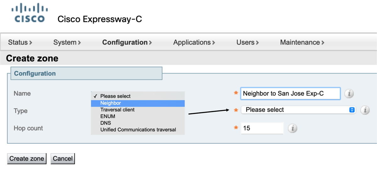
Figure 9-11 Create Zone Configuration Menu on Expressway Core
1. Log into the web interface of the Expressway Core and navigate to Configuration > Zones > Zones.
2. Click New and enter the following information:
![]() Name: Create something logical, such as Neighbor to San Jose Exp-E
Name: Create something logical, such as Neighbor to San Jose Exp-E
![]() Type: Neighbor Zone
Type: Neighbor Zone
![]() Hop count: leave as 15
Hop count: leave as 15
Once the Zone Type is selected additional menu options will expand out based on the Zone type selected. Figure 9-12 illustrates the H.323 and SIP menu options for a Neighbor Zone.
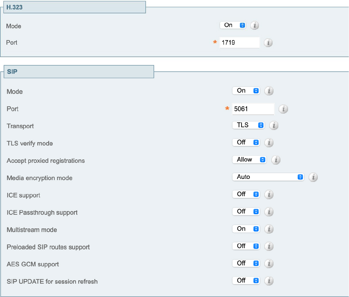
Figure 9-12 H.323 and SIP Neighbor Zone Menus
3. If you do not plan to support H.323, turn off this protocol. Otherwise, just leave the settings at their default values.
4. Most of the SIP settings can be left to their default values as well. However, if you change the SIP transport then you will need to change the port as well. TCP uses port 5060 and TLS uses port 5061.
There are three other sections that need to be configured for a Neighbor Zone. They are Authentication, Location and Advanced. Figure 9-13 illustrates the menu options for these sections.
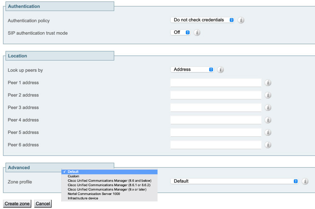
Figure 9-13 Authentication, Location and Advanced Neighbor Zone Menus
5. Authentication refers to the same security policy service described in Chapter 6. This setting can be configured as Do not check credentials, Check credentials, or Treat as authenticated. How Call Policy can be configured to impact this Zone is in part determined by how Authentication policy is configured. As with Subzones, best practice is to set Authentication policy to either Check credentials or Treat as authenticated.
6. The Location section is where the address of the destination server is entered. You can use either the address or the SRV record of the destination. The address could be the URL or the Ipv4 address. There are six Peer address fields that can be configured. If you were trying to neighbor a local Expressway to two other Expressways that were disparate from one another, you would not want to use two peer address slots in one Neighbor Zone for those two neighbor relationships. You would want to create two different Neighbor Zones, one for each peer respectively. Since Expressways can be clustered with up to six peers in a cluster, there is an entry slot for each of the peer addresses within the cluster. You would not use the cluster FQDN, rather you would use the six unique addresses of each peer in the cluster.
7. The last section is the Advanced section. If Neighbor Zones are being established between two Cisco Expressway servers, then the Zone profile can be left as Default. If the Neighbor Zone points to a different server type, such as the CUCM or Cisco Meeting Server, then changes may be required.
8. Click Create zone. This step takes you back to the Zones page. The Zone that you created should show active for both H.323 and SIP, assuming both protocols were left active.
9. The last step is to create at least one Search Rule for the Neighbor Zone. Refer to the sub-section Search Rules that was covered towards the beginning of this chapter to review the components and menu options for creating Search Rules.
Expressway to CUCM Neighbor Zone
As mentioned in the previous section, creating a Neighbor Zone to the CUCM from an Expressway Core is similar to creating a Neighbor Zone to another Expressway Core. However, there are a few differences. H.323 must be disabled because the CUCM does not support H.323 communication. Now I know some of you reading this book are going to say, “That’s not true. The CUCM can support H.323 because you can create an H.323 gateway.” To that I would say, there are big differences between supporting an H.323 gateway and supporting H.323. H.323 endpoints cannot register directly to the CUCM without another device standing between the CUCM and the H.323 endpoint. Also, there are no H.323 gatekeeper functions within the CUCM.
The Location section is not treated different, per se, for the CUCM. However, you can support more than six peers within a CUCM cluster. Therefore, Cisco recommends that if a Neighbor Zone is being created on an Expressway Core to a CUCM cluster, that only the peer addresses be used of the CUCMs running the Call Manager service.
The third difference to creating a Neighbor Zone from an Expressway Core to the CUCM was mentioned in the previous section. Under the Advanced section, the Zone profile needs to be changed. To ease changing these settings, Cisco has some pre-configured template settings you can choose from based on the version of CUCM you are running. The custom template options of the CUCM for the Zone profile include the following:
![]() Cisco Unified Communications Manager (8.6 and below)
Cisco Unified Communications Manager (8.6 and below)
![]() Cisco Unified Communications Manager (8.6.1 or 8.6.2)
Cisco Unified Communications Manager (8.6.1 or 8.6.2)
![]() Cisco Unified Communications Manager (9.x or later)
Cisco Unified Communications Manager (9.x or later)
Beyond those three differences, creating a Neighbor Zone on the Expressway Core to the CUCM is the same as creating a Neighbor Zone to another Expressway Core. Do not forget to create the Search Rule. No Zone will be searched on any Expressway without at least one Search Rule. Unfortunately, the Neighbor Zone to a CUCM will not show up as active unless an active SIP Trunk exists on the CUCM that points to the Expressway Core. However, a CUCM SIP Trunk to an Expressway Core will show active without a Neighbor Zone ever being created. Therefore, it is best practice to create the SIP Trunk on the CUCM first, then go back and create the Neighbor Zone on the Expressway Core. Creating a SIP trunk from a CUCM is a complicated process that includes 4 basic steps:
1. Configure a SIP Trunk Security Profile
2. Configure a SIP Trunk
3. Configure a Route Pattern
4. Transform the pattern once it arrives at the Cisco VCS
The first step is to create a SIP Trunk Security Profile on the CUCM. Follow the steps below Figure 9-14, which illustrates these settings in the SIP Trunk Security Profile on the CUCM.
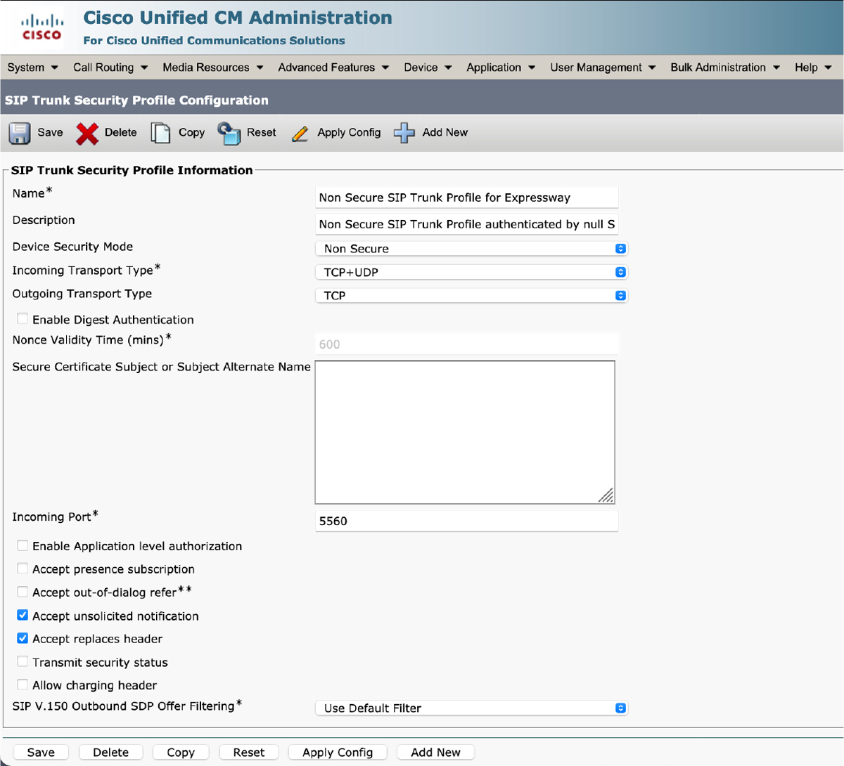
Figure 9-14 SIP Trunk Security Profile on CUCM
1. Log into the web interface of the CUCM, and then navigate to System > Security > SIP Trunk Security Profile
2. Click Add New and configure the following fields:
![]() Name: Non Secure SIP Trunk Profile for Exp-C
Name: Non Secure SIP Trunk Profile for Exp-C
![]() Device Security Mode: Non Secure
Device Security Mode: Non Secure
![]() Incoming Transport Type: TCP+UDP
Incoming Transport Type: TCP+UDP
![]() Outgoing Transport Type: TCP
Outgoing Transport Type: TCP
![]() Incoming Port: You can use 5060 for SIP communication if it hasn’t been used by another SIP Trunk Security Profile. Otherwise you may need to use a different port, such as 5560. If you use a different port, be sure to change the SIP port of the Neighbor Zone on the Expressway to match.
Incoming Port: You can use 5060 for SIP communication if it hasn’t been used by another SIP Trunk Security Profile. Otherwise you may need to use a different port, such as 5560. If you use a different port, be sure to change the SIP port of the Neighbor Zone on the Expressway to match.
![]() Check Accept Unsolicited Notifications
Check Accept Unsolicited Notifications
![]() Check Accept Replaces header
Check Accept Replaces header
3. Click Save.
The second step is to create a SIP Trunk on the CUCM. There are many different settings that can be configured on a SIP Trunk. Which settings must be configured is entirely dependent on the customer environment, and will very greatly from customer to customer. The following steps merely outline the most basic settings that must be configured to support an active SIP Trunk to an Expressway Core.
1. From the CUCM web interface, navigate to Device > Trunk.
2. Click Add New and enter the following information.
![]() In the Trunk Type field, choose SIP Trunk from the dropdown menu. This will populate the following two fields.
In the Trunk Type field, choose SIP Trunk from the dropdown menu. This will populate the following two fields.
![]() In the Device Protocol field, leave the setting as SIP.
In the Device Protocol field, leave the setting as SIP.
![]() In the Trunk Service Type field, leave the setting as None (Default).
In the Trunk Service Type field, leave the setting as None (Default).
3. Clicking the Next button will open several other sections and fields that will need to be configured for this SIP Trunk. Figure 9-15 illustrated the three previously mentioned fields.
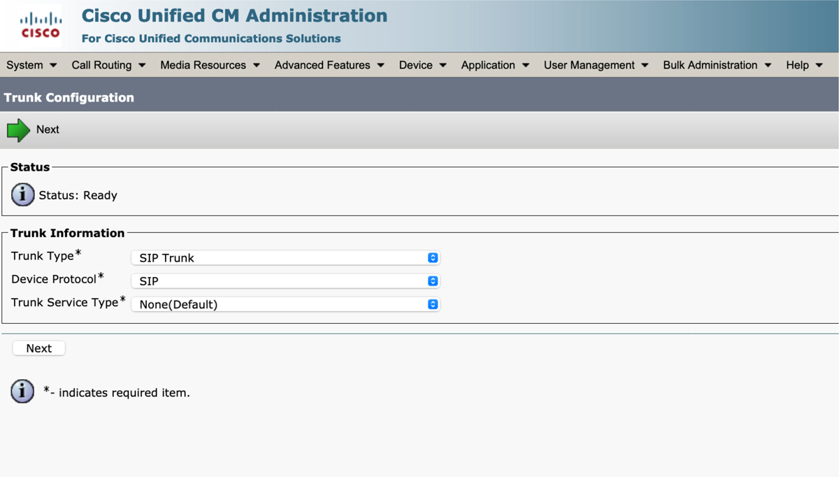
Figure 9-15 SIP Trunk Menu Selection on the CUCM
4. In the Device Information screen, enter the following criteria:
![]() Device Name: Choose a descriptive name for the SIP Trunk. Spaces cannot be used, but underscores or dashes can be used to replace spaces.
Device Name: Choose a descriptive name for the SIP Trunk. Spaces cannot be used, but underscores or dashes can be used to replace spaces.
![]() Device Pool: You must choose a Device Pool for every trunk. If you have not created a Device Pool, you can choose Default, which has been pre-configured on the CUCM. There are a great number of settings between Device Pool and step 5 that I am not covering. Remember, I am only identifying the most basic settings that must be configured on a SIP Trunk to an Expressway Core.
Device Pool: You must choose a Device Pool for every trunk. If you have not created a Device Pool, you can choose Default, which has been pre-configured on the CUCM. There are a great number of settings between Device Pool and step 5 that I am not covering. Remember, I am only identifying the most basic settings that must be configured on a SIP Trunk to an Expressway Core.
5. In the SIP Information section, enter the following criteria:
![]() Destination Address is an SRV:
Destination Address is an SRV:
• Enabled if SRV records are used by the CUCM to locate the Cisco Expressway Core. This setting is required when TLS is being used.
• Do not enabled if IP addresses are used. This is typical for TCP communication.
![]() Destination Address: Enter appropriate IP address.
Destination Address: Enter appropriate IP address.
![]() Destination Port: Enter appropriate port number. Use 5060 for TCP and 5061 for TLS. The Inbound Port configured on the SIP Trunk Security Profile is not to be used here. This is an outbound port not an inbound port. If SRV records are used, the Destination Port field displays as 0.
Destination Port: Enter appropriate port number. Use 5060 for TCP and 5061 for TLS. The Inbound Port configured on the SIP Trunk Security Profile is not to be used here. This is an outbound port not an inbound port. If SRV records are used, the Destination Port field displays as 0.
![]() SIP Trunk Security Profile: Select the Non Secure SIP Trunk Profile for Expressway that was created previously.
SIP Trunk Security Profile: Select the Non Secure SIP Trunk Profile for Expressway that was created previously.
![]() SIP Profile: Choose the Standard SIP Profile for Cisco VCS∫, which is a pre-configured SIP Profile on the CUCM.
SIP Profile: Choose the Standard SIP Profile for Cisco VCS∫, which is a pre-configured SIP Profile on the CUCM.
![]() Normalization Script: SIP normalization and transparency is an optional feature that handles SIP interoperability issues between the CUCM and endpoints, service providers, PBXs, or gateways that implement SIP differently. The Cisco Expressway is no exception to this list. Therefore, you should select the VCS-Interop normalization script.
Normalization Script: SIP normalization and transparency is an optional feature that handles SIP interoperability issues between the CUCM and endpoints, service providers, PBXs, or gateways that implement SIP differently. The Cisco Expressway is no exception to this list. Therefore, you should select the VCS-Interop normalization script.
6. Click Save. Once the page refreshes, click Reset. A popup will appear, at which time you should click Reset again and then click Close.
Every trunk on the CUCM must be reset, whether you are creating the trunk for the first time or making a change to an existing trunk. Without a reset the trunks will not come up properly and could cause communication issues. Figure 9-16 illustrates the basic settings that must be configured on a SIP Trunk to an Expressway Core from a CUCM.

Figure 9-16 Basic SIP Trunk Settings on the CUCM
The third step is to create dialing rules that will match alias patterns so that the CUCM knows when to route calls across this trunk to the Expressway Core. These dialing rules perform the same function on the CUCM as Search Rules perform on the Expressway Core. However, how these rules are created is quite different. There are two different type of patterns that can be created. They are Route Patterns and SIP Route Patterns. These two pattern types can be used exclusively or tandem with one another to match any trunk. You can also create multiple patterns of each type for any one trunk.
Route Patterns are routing rules that match numeric digits. Since the primary phone extension used on the CUCM is a Directory Number (DN), which is the same as an E.164 alias, it makes sense to use Route Patterns for routing to and from DNs. An “x” represents a single digit. This allows for patterns to be created that match multiple aliases. For Example, if the alias of every endpoint registered to the Expressway Core started with the number 4, and was four digits long, you could create a Route Pattern of 4xxx. Use the following steps to create a Route Pattern.
1. On the CUCM navigate to Call Routing > Route Hunt > Route Pattern.
2. Click Add New and configure the following parameters:
![]() Route Pattern: This is where you can enter something like 4xxx
Route Pattern: This is where you can enter something like 4xxx
![]() Route Partition: The default value is <None>, but you can choose another partition if one has been created.
Route Partition: The default value is <None>, but you can choose another partition if one has been created.
![]() Gateway/Route List: This is where you select the SIP Trunk you created previously.
Gateway/Route List: This is where you select the SIP Trunk you created previously.
![]() Call Classification: This can be set to OnNet or OffNet. OffNet is used for toll charges that are routed across the PSTN. Since calls to the Expressway Core are over IP, change this setting to OnNet.
Call Classification: This can be set to OnNet or OffNet. OffNet is used for toll charges that are routed across the PSTN. Since calls to the Expressway Core are over IP, change this setting to OnNet.
3. There are other settings that can be configured under Route Patterns, but these are all the basic settings you will need to configure. Once you are finished click Save.
Where Route Patterns are used for numeric only digits, SIP Route Patterns are used for SIP URI dialing. You can perform SIP URI dialing within the CUCM without ever creating a SIP Route Pattern. Therefore, SIP Route Patterns are designed to match the second part of the URI. This can be a little bit confusing, so let me explain some terminology. The IETF defines a SIP URI as having two parts; the Host portion and the Domain, or FQDN, portion. So, if I took the URI [email protected], then john would be the host and cisco.com would be the domain or FQDN. Within the CUCM the parts of a URI are defined a little bit different. The first part is called the User portion and the second part is called Host portion. Now, if you tool the same URI [email protected], then john would be the user and cisco.com would be the host.
The reason this is so important to understand relates to how a SIP Route Pattern is configured. When you enter the Ipv4 Pattern string you should only enter the host portion of the URI, which is to say the domain or FQDN. The @ sign is not a recognizable character and the user portion will not result in a successful search. With all that said, use the following steps to configure a SIP Route Pattern.
1. From the CUCM, navigate to Call Routing > SIP Route Pattern.
2. Click Add New and configure the following settings:
![]() Pattern Usage: leave this setting set to Domain Routing
Pattern Usage: leave this setting set to Domain Routing
![]() Ipv4 Pattern: Enter the Host (domain or FQDN) portion of the URI.
Ipv4 Pattern: Enter the Host (domain or FQDN) portion of the URI.
![]() Route Partition: The default value is <None>, but you can choose another partition if one has been created.
Route Partition: The default value is <None>, but you can choose another partition if one has been created.
![]() SIP Trunk/Route List: This is where you select the SIP Trunk you created previously.
SIP Trunk/Route List: This is where you select the SIP Trunk you created previously.
3. Again, there are other settings that can be configured under SIP Route Patterns, but these are all the basic settings you will need to configure. Once you are finished click Save. Figure 9-17 illustrates the Route Pattern and SIP Route Pattern menu options.
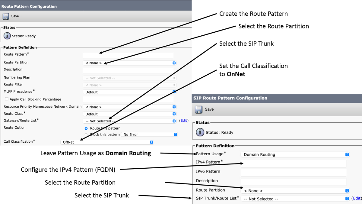
Figure 9-17 Route Patterns and SIP Route Patterns on the CUCM
Everything configured up to this point on the CUCM will enable calls to be forwarded to the Expressway Core. How the aliases are presented when sent to the Expressway is determined by other settings on the CUCM. So long as the CUCM is setup to use DNS, a domain configured on the CUCM will be appended at the end of all aliases, even if a DN is dialed. If the domain on the CUCM was cisco.com and a phone registered to the CUCM dialed 4001, then the Route Pattern previously described would make the match and send the alias [email protected] to the Expressway Core. So long as this is how the endpoint alias appears, the phones should connect and the call will go through. However, of the CUCM is not setup to use DNS, then the IP address of the destination will be appended to every DN along with the port. Use the same scenario as before, if a phone on the CUCM dials 4001, then the Route Pattern previously described would make the match, but the alias that would be sent to Expressway Core would look more like [email protected]:5060. This is clearly not how the endpoint is registered to the Expressway Core, therefore there is one more step that must be completed to enable calls from the CUCM to the Expressway Core.
The fourth step in building a peer relationship between the CUCM and Expressway Core is to create a Transform on the Expressway Core to handle incoming calls from the CUCM. Since Transforms were already covered in Chapter 7, “Configure Expressway Core Dial Plan Elements,” I will only demonstrate a pattern you can use to make this transformation. Assuming the destination alias is registered to the Expressway via SIP with the domain cisco.com, I would recommend using a regular expression pattern match that looks something like this:
Pattern type: Regex
Pattern string: ([4]d{3})@192.168.100.40(:5060|:5061)?
Pattern behavior: Replace
Replace string: [email protected]
The first part of this pattern matches anything that begins with a 4 followed by three more digits and an @. The next part is a pattern match for the IP address 192.168.100.40. Notice that each dot has a back slash preceding it. This is a literalization that clarifies each dot is literally a dot. In regular expressions a dot by itself could be any one number letter or character. Therefore, it is best practice to literalize the dot when it should represent a literal dot. The last part will match either port :5060 or :5061 or neither. The question mark at the end signifies the contents of the last set of parentheses could exist in the pattern match or not. Once the pattern match is made, only the contents of the first set or parenthesis should be kept followed by the domain @cisco.com. This is why the replace string is stated as 1, which represents the first group or parenthesis set, followed by the @cisco.com. Figure 9-18 illustrates how this transform should be configured.

Figure 9-18 Transform on Expressway for Incoming calls from the CUCM
Exam Preparation Tasks
As mentioned in the section “How to Use This Book” in the Introduction, you have a couple of choices for exam preparation: the exercises here, Chapter 22, “Final Preparation,” and the exam simulation questions in the Pearson Test Prep Software Online.
Review All Key Topics
Review the most important topics in this chapter, noted with the Key Topics icon in the outer margin of the page. Table 9-2 lists a reference of these key topics and the page numbers on which each is found.
Table 9-2 Key Topics for Chapter 9

Complete Tables and Lists from Memory
There are no Memory Lists of Tables for this chapter.
Define Key Terms
Define the following key terms from this chapter and check your answers in the glossary:
Unified Communications Traversal Zone
Q&A
The answers to these questions appear in Appendix A. For more practice with exam format questions, use the Pearson Test Prep Software Online.
1. List the three different Traversal Zones that can be configured on the Cisco Expressway?
2. List the recommended order Zones should be searched on the Cisco Expressway.
3. List five advantages of a hierarchical video network with a structured dial plan.
4. What are the four basic steps to creating a SIP Trunk from the CUCM to the Expressway Core?
Answers
1. Three Traversal Zones
a. Traversal Client Zone
b. Traversal Server Zone
c. Unified Communications Traversal Zone
2. Zone Search Order
a. Local Zone
b. Neighbor Zones
c. Traversal Zones
d. DNS and ENUM Zones
3. five advantages of a hierarchical video network with a structured dial plan
a. More scalable solution
b. Full Mesh not needed (not all Expressway need to neighbor to each other)
c. Minimized number of LRQs for each call attempt
d. Calls only consume bandwidth within the local Expressway locations
e. Some Resiliency when Expressways go down
4. four basic steps to creating a SIP Trunk from the CUCM to the Expressway Core
a. Configure a SIP Trunk Security Profile
b. Configure a SIP Trunk
c. Configure a Route Pattern
d. Transform the pattern once it arrives at the Cisco VCS