Chapter 10. Multisite and Business-to-Business (B2B) Collaboration Solutions
This chapter covers the following topics:
![]() Firewall Issues in a Collaboration Environment: This topic will examine firewall issues that could prevent UDP media packets from routing through a corporate firewall, whereby preventing audio and video calls from connecting.
Firewall Issues in a Collaboration Environment: This topic will examine firewall issues that could prevent UDP media packets from routing through a corporate firewall, whereby preventing audio and video calls from connecting.
![]() NAT Issues in a Collaboration Environment: This topic will examine NAT issues that could prevent UDP media packets from routing through a network edge NAT server, whereby preventing audio and video calls from connecting.
NAT Issues in a Collaboration Environment: This topic will examine NAT issues that could prevent UDP media packets from routing through a network edge NAT server, whereby preventing audio and video calls from connecting.
![]() Purpose of STUN, TURN and ICE: This topic will examine the IETF solutions to NAT traversal, identifying the strengths and weaknesses of each solution, and the limitations of the solution as a whole.
Purpose of STUN, TURN and ICE: This topic will examine the IETF solutions to NAT traversal, identifying the strengths and weaknesses of each solution, and the limitations of the solution as a whole.
![]() Expressway Media Traversal: This topic will identify two highly secure and very effective firewall and NAT traversal solutions that work in a Cisco collaboration deployment using Expressway Core and Edge servers. This topic will also outline the steps needed to configure this solution, and overview different deployment options pertaining to firewall traversal.
Expressway Media Traversal: This topic will identify two highly secure and very effective firewall and NAT traversal solutions that work in a Cisco collaboration deployment using Expressway Core and Edge servers. This topic will also outline the steps needed to configure this solution, and overview different deployment options pertaining to firewall traversal.
![]() DNS Zones: This topic will explain how DNS can be used for both internal routing and external routing for Business-to-Business communications. This topic will also outline how to configure DNS Zones on the Cisco Expressway Edge server.
DNS Zones: This topic will explain how DNS can be used for both internal routing and external routing for Business-to-Business communications. This topic will also outline how to configure DNS Zones on the Cisco Expressway Edge server.
Chapter 9, “Multisite Collaboration Solutions,” introduced Zones, and then focused on Neighbor Zones. This chapter will examine two other types of Zones that can be used to extend IP communications outside the organizations network to other businesses or customers. To achieve this goal there are some firewall and NAT obstacles that must be overcome first. Traversal Zones are used to aid in overcoming these issues. Once outside the network DNS Zones can be used to resolve publicly registered domains to routable IP addresses.
This chapter covers the following objectives from the Implementing Cisco Collaboration Cloud and Edge Solutions (CLCEI) exam 300-820:
![]() 1.1 Describe the complications of NAT in a Collaboration environment
1.1 Describe the complications of NAT in a Collaboration environment
![]() 1.2 Describe the purpose of ICE, TURN and STUN
1.2 Describe the purpose of ICE, TURN and STUN
![]() 1.3 Describe Expressway media traversal
1.3 Describe Expressway media traversal
![]() 2.4 Configure a Business to Business (B2B) collaboration solution
2.4 Configure a Business to Business (B2B) collaboration solution
![]() 2.4.a DNS records (focus on Microsoft DNS)
2.4.a DNS records (focus on Microsoft DNS)
![]() 2.4.c Traversal Zones
2.4.c Traversal Zones
“Do I Know This Already?” Quiz
The “Do I Know This Already?” quiz allows you to assess whether you should read this entire chapter thoroughly or jump to the “Exam Preparation Tasks” section. If you are in doubt about your answers to these questions or your own assessment of your knowledge of the topics, read the entire chapter. Table 10-1 lists the major headings in this chapter and their corresponding “Do I Know This Already?” quiz questions. You can find the answers in Appendix A, “Answers to the ‘Do I Know This Already?’ Quizzes.”
Table 10-1 ”Do I Know This Already?” Section-to-Question Mapping

Caution
The goal of self-assessment is to gauge your mastery of the topics in this chapter. If you do not know the answer to a question or are only partially sure of the answer, you should mark that question as wrong for purposes of the self-assessment. Giving yourself credit for an answer you correctly guess skews your self-assessment results and might provide you with a false sense of security.
1. In which of the following circumstances will a firewall typically allow communications packets into a network from an outside source?
a. A firewall will never allow an outside source to send packets into a private network.
b. A firewall will always allow an outside source to send packets into a private network.
c. When sending UDP packets in response to communication originating from inside the network.
d. When sending TCP packets in response to communication originating from inside the network.
2. Which of the following is a Class B Private IP address?
a. 10.1.1.10
b. 172.32.1.10
c. 172.28.1.10
d. 192.168.168.10
3. Which of the following NAT traversal solutions is recommended for A-symmetric networks?
a. ICE
b. TURN
c. STUN
d. ASSENT
e. H.460.18/19
4. Which of the following is the only IETF service available on the Expressway Edge server for traversal?
a. ICE
b. TURN
c. STUN
d. ASSENT
e. H.460.18/19
5. Which of the following IETF traversal solutions will always enable a connection regardless of the number of NATs involved?
a. ICE
b. TURN
c. STUN
d. ASSENT
e. H.460.18/19
6. What ports does H.460.18 use for RTP and RTCP packets?
a. 2776 and 2777
b. 36,000 and 36001
c. 36,000 to 59,999
d. 1024 to 34545
7. What type of Traversal Zones can be configured on the Expressway Edge server?
a. Traversal Client Zone
b. Traversal Server Zone
c. Unified Communications Traversal Zone
d. All Zone types
e. Only Unified Communications Traversal Zones and Traversal Server Zones
8. What type of Traversal Zones can be configured on the Expressway Core server?
a. Traversal Client Zone
b. Traversal Server Zone
c. Unified Communications Traversal Zone
d. All Zone types
e. Only Unified Communications Traversal Zones and Traversal Client Zones
9. Which of the following deployment scenarios for firewall traversal through a DMZ does Cisco recommend?
a. Single Subnet DMZ Deployment Scenario
b. Three Port Firewall DMZ Deployment Scenario
c. Dual NIC DMZ Deployment Scenario
d. Triple Expressway Deployment Scenario
10. Which of the following is a Zone type on the Cisco Expressway that allows E.164 aliases to be mapped to URIs for domain routing?
a. ENUM Zone
b. DNS Zone
c. Traversal Server Zone
d. Traversal Client Zone
Foundation Topics
Firewall Issues in a Collaboration Environment
Communication over IP has come a long way in a short time. One huge obstacle that had to be overcome before companies could really start migrating away from PSTN-based communication to IP-based communication was how to securely route network traffic through firewalls and across NAT servers.
Allowing uninhibited traffic into and out from a corporate network allows hackers unconstrained access to private information. Therefore, a firewall exists to protect the inside of a corporate network from outside attacks by controlling IP traffic entering your network. Firewalls can be a software or hardware device designed to block unsolicited incoming requests from outside a private networked environment, meaning that any communication originating from outside your network will be prevented. However, firewalls can be configured to allow outgoing requests to certain trusted destinations, and to allow responses from those destinations.
Most firewalls use ports to mark TCP outgoing traffic so that reply messages from outside the network coming in on the same ports will be allowed back into the private corporate network. This means that any two-way communication must be started by an internal system. An example of this type of communication could be when a user within an enterprise network browses to Google.com from a web browser. A TCP communication is sent through the firewall, which marks the packets, then forwards the request to the Google Web server. When the Google server sends back the response, the firewall is already expecting this response so the communication is allowed to come in and is redirected to the requesting application.

In a similar manner, a video call made from an endpoint inside a network through a firewall to an outside endpoint begins with a TCP communication. The firewall will allow the exchange of TCP call setup information and allow UDP media packets originating from an inside endpoint to be sent to an outside endpoint. However, the media traffic in the opposite direction does not come back on the same ports. The firewall observes these communication packets as originating from outside the network and block those packets from ever reaching the internal endpoint. This is a common issue, and it is referred to as One-Way-Audio and One-way-Video. Notice also that to even get to this point in the call setup process, the call had to originate from inside the network. Inbound calls originating from outside the network are out of the question. Two endpoints located behind two different firewalls would never be able to call each other. The seemingly obvious resolution to this issue would be to open the ports needed for two-way communication, however this will not work for two reasons. First, opening the ports on the firewall will leave the network vulnerable to attacks from outside the network. The very reason for the firewall’s existance would be negated by this action. Second, there is another issue related to NAT that could still prevent endpoints from communicating with each other even if there was no firewall.
NAT Issues in a Collaboration Environment
The Institute of Electrical and Electronic Engineers (IEEE) first introduced communication using packet-switched technology in 1974. Several Internet Protocol Versions were experimented with (IPv1-3) until the predominant protocol was established in circa 1981 called Internet Protocol version 4 (IPv4). At that time engineers couldn’t imagine the four billion addresses made available with IPv4 would ever run out. Initially anyone could purchase IP addresses in pools, and they would own them for life. Telco companies and universities were some of the main consumers of these IP addresses. As the number of devices that required an IP address greatly increased, and the World Wide Web began to expand, it was realized that the number of people and devices requiring an IP address would soon eclipse the finite number of IPv4 addresses available. One solution to this problem was the introduction of Internet Protocol version 6 (IPv6), which contains 340 undecillion addresses. Some say you could assign an IPv6 address to every grain of sand on earth and still not run out of addresses. However, IPv6 introduces other issues, like how do you migrate hundreds of millions of devices over to an IPv6 network that are already established under IPv4.
Another resolution that came about around the same time as IPv6 was Network Address Translation (NAT). The IETF came up with RFC 2663 outlining the basic use of NAT. In order for NAT to work IP addresses first had to be divided into two pools; Public and Private IP addresses. ICANN (Internet Cooperation for Assigned Names and Numbers) was created in 1998 to assume responsibility for managing IP addresses and Domains. Private IP addresses are designated in the following categories, which anyone can use, but are not routable across the public Internet. The ranges for private IP addresses are:
![]() Class A Addresses 10.0.0.0-10.255.255.255 has 16,777,216 available addresses
Class A Addresses 10.0.0.0-10.255.255.255 has 16,777,216 available addresses
![]() Class B Addresses 172.16.0.0-172.31.255.255 has 1,048,576 available addresses
Class B Addresses 172.16.0.0-172.31.255.255 has 1,048,576 available addresses
![]() Class C Addresses 192.168.0.0-192.168.255.255 has 65,536 available addresses.
Class C Addresses 192.168.0.0-192.168.255.255 has 65,536 available addresses.
Public IP addresses are routable across the public Internet and can be leased from an Internet service provider. Today there are different versions of NAT that can be used based on many different factors. However, the basis of how NAT works is a private IP address is masqueraded with a public IP address when a device needs to route across the public Internet. For example, if a computer assigned a private IP address of 10.10.1.14 tries to navigate to Google.com, the edge router will masquerade that private IP address with its assigned public IP address of 209.165.201.1. When the Google server returns communication to the edge router at the public IP address, the router will then change the destination address from 209.165.201.1 to the Private IP Address of the endpoint, 10.10.1.14, and route the packets sent from Google to the computer that initiated the communication. A limitation to this type of NAT solution could arise from the number of outgoing communication devices exceeding the number of public IP addresses available. A simple resolution could be to use Port Address Translation (PAT).
Similar to NAT is another protocol called PAT. Sometimes NAT and PAT can be used together. Similar to the previous scenario, the router will masquerade the IP address and mark the packets going out with a virtual port number to enable routing return traffic to the desired destination. For example, if a computer assigned a private IP address of 10.10.1.14 tries to navigate to Google.com, the edge router will masquerade that private IP address with its assigned public IP address of 209.165.201.1:12345. Notice the port tagged on to the end of the IP address. When the Google server returns communication to the computer, return traffic will go to the edge router, but the port :12345 tagged at the end of the IP address indicates to the router where to send the return traffic based on a table the router keeps. The router will then change the destination address from 209.165.201.1:12345 to the Private IP Address of the endpoint, 10.10.1.14, and route the packets sent from Google to the computer that initiated the communication. In this manner a single public IP address can be used to masquerade private IP addresses from multiple devices by simply using a different port for each device.
NAT becomes an issue with collaboration devices for two reasons. First, NAT doesn’t allow communication to be initiated from outside the private network because the virtual ports can change with each new transmission that is created. So, if two video endpoints behind different NATs wanted to communicate, one will never be able to discover the other. For Example, if a device were to try and route to the private IP address of another endpoint, the transmission would fail at the source router, because private IP addresses are not publicly routable. Alternatively, if the source device tried to route to the public IP address of the far end router, once the packets arrived, the far end router wouldn’t know to which device the packets should be routed within the private network.
The 2nd issue that comes with NAT has to do with UDP (User Datagram Protocol) transmissions. Where TCP communications require a response, UDP communications are unidirectional. Once video calls are set up using TCP, the audio and video packets are sent using UDP. Since each UDP packet sent is essentially a new transmission, a different virtual port is used, and transmissions will never reach their targeted destination.
Purpose of STUN, TURN and ICE
The IETF, who came up with the SIP communications protocol and NAT, also came up with the first solution that allowed communication between private networks through a NAT Server. That protocol is known as Session Traversal Utilities for NAT (STUN). After creating the RFC for STUN, The IETF came up with two other RFC protocols know as Traversals Using Relays around NAT (TURN) and Interactive Connectivity Establishment (ICE).
STUN, TURN and ICE are methods that assume certain behavior from the NAT and firewall and do not work in all scenarios. The control is removed from the firewall, which has to be sufficiently opened to allow clients to create the pinholes needed to let the communication through. Therefore STUN, TURN and ICE only offer a NAT traversal solution, and are not a firewall traversal solution at all. Also, these solutions can only operate within the SIP communications protocol, so they offer no solution for H.323 communications.
STUN
STUN requires a STUN client, which could be the phone or some other device, and a STUN Server. The client will initiate communication to the STUN server by sending a port request packet to the STUN server, which should be located outside the NAT server. The NAT server will masquerade the IP address and port before forwarding the information to the STUN server. The STUN server will then MAP that assigned port to the client and send back a reply. Both the NAT server and client will record the port assignment so that all future inbound packets sent on this port will be forwarded to the client. Once the STUN server assigns a port, it is no longer involved in the line of communication.
STUN requires that the NAT server allow all traffic that is directed to a particular port to be forwarded to the client on the inside. This means that STUN only works with less-secure NATs, so-called “full-cone” NATs exposing the internal client to an attack from anyone who can capture the STUN traffic. STUN may be useful within Asymmetric network environments but is generally not considered a viable solution for enterprise networks. In addition, STUN cannot be used with symmetric NATs. This may be a drawback in many situations as most enterprise-class firewalls are symmetric. For more information about STUN see RFC 5389. Figure 10-1 illustrates how STUN works within a network.
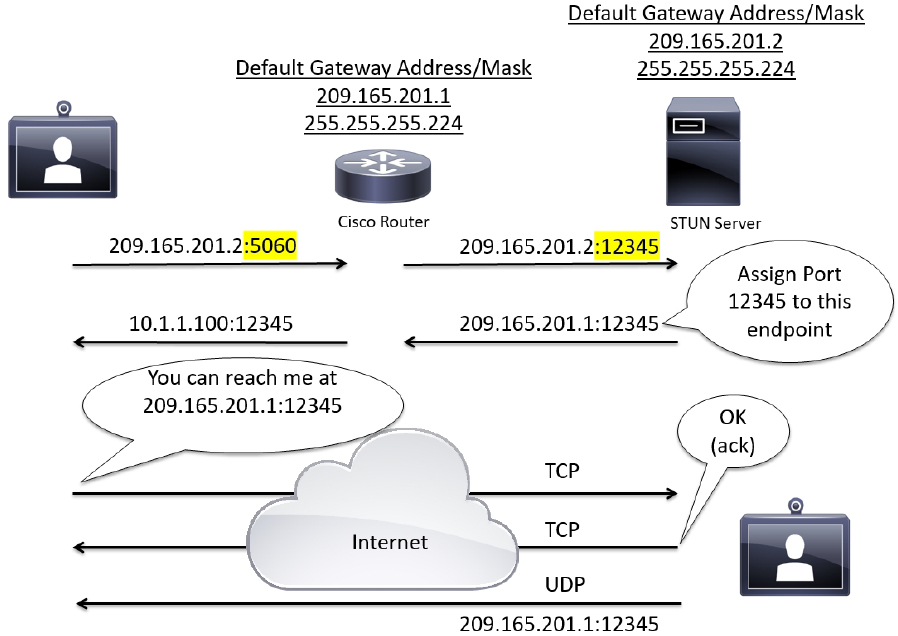
Figure 10-1 STUN Operation within an Asymmetric Network
TURN
TURN operates similarly to STUN, but it allows aa client behind a firewall to receive SIP traffic on either TCP or UDP ports. This solves the problems of clients behind symmetric NATs, which cannot rely on STUN to solve the NAT traversal issue. TURN connects clients behind a NAT to a single peer. Its purpose is to provide the same protection as that created by symmetric NATs and firewalls. Symmetric NATs use dynamic ports that often change. Therefore, the TURN server acts as a relay so that any data received is forwarded on to the client, and port allocation can be updated on the fly. The client on the inside can also be on the receiving end of a connection that is requested by a client on the outside.
This method is appropriate in some situations, but since it essentially allows inbound traffic through a firewall, with only the client in control, it has limited applicability for enterprise environments. It also scales poorly since the media must traverse through the TURN server. Also, since all media must traverse the TURN server, the server supporting TURN must be robust enough to handle high volumes of traffic. For more information about TURN see RFC 5766. Figure 10-2 illustrates how TURN works within a network.
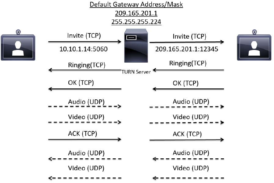
Figure 10-2 TURN Operation within a Symmetric Network
TURN relay services are the only IETF services available on the Expressway-E. To use TURN services, the TURN Relay option key is needed. This controls the number of TURN relays that can be simultaneously allocated by the TURN server. The TURN configuration page on the Expressway web interfacecan be found under the Configuration > Traversal > TURN menu. The settings on this page are used to configure the Expressway-E’s TURN settings. Table 10-2 identifies the configurable options for TURN on the Cisco Expressway.
Table 10-2 Configurable Options for TURN on the Cisco Expressway
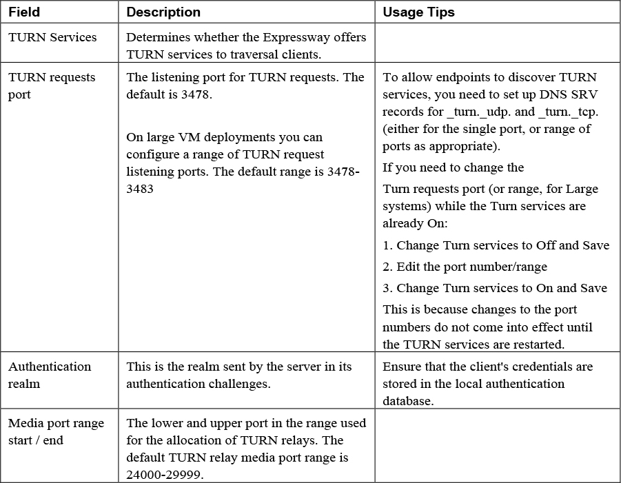
A summary of the TURN server status is displayed at the bottom of the TURN page. When the TURN server is active, the summary also displays the number of active TURN clients and the number of active relays. Click on the active relay links to access the TURN relay usage page, which lists all the currently active TURN relays on the Expressway. Further details of each TURN relay can be reviewed including permissions, channel bindings and counters.
ICE
ICE provides a mechanism for SIP client NAT traversal. ICE is not a protocol, but a framework which pulls together a number of different techniques such as TURN and STUN. It allows clients residing behind NAT devices to discover paths through which they can pass media, verify peer-to-peer connectivity via each of these paths and then select the optimum media connection path. The available paths typically depend on any inbound and outbound connection restrictions that have been configured on the NAT device. Such behavior is described in RFC 4787. ICE essentially incorporates all of the methods proposed for NAT traversal of SIP that do not rely on the firewall or NAT device. ICE is a complex solution to the problem of NAT traversal, but since it encompasses multiple solutions it is regarded as one that will always enable the connection, regardless of the number of NATs involved. However, ICE still relies on client-server-based approaches and removes control from the enterprise. Due to its complexity, there is very limited client support for ICE today.
When a client reaches out to the ICE server, it has the ability to determine what type of NAT is being used; whether it’s in an Asymmetric or Symmetric network environment. The ICE server will then establish a connection with the client using STUN or TURN, depending on what the situation calls for. If STUN is used, then the ICE server will assign a port to the client and step out of the line of communication. If TURN is used, then the ICE server will act as the relay between client communications. For more information about ICE, see RFC 5245. Figure 10-3 illustrates how ICE works within a network.
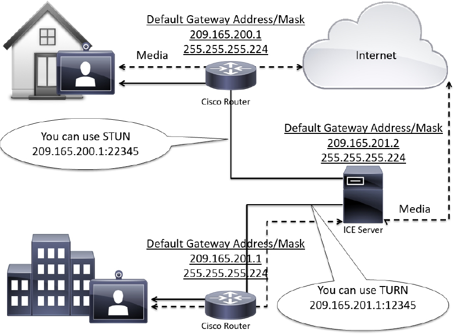
Figure 10-3 ICE Operation within Asymmetric and Symmetric Networks
Expressway Media Traversal
Although the IETF overcame many problems, there were still many more to overcome. Their solutions, although good, were incomplete. As mentioned before, the IETF solutions only support SIP communication and they only traverse NATs. In order to account for the firewall, many port need to be opened for the media flows. In fact, most IETF NAT traversal solutions require over 30,000 UDP ports to be open. Some of the more conservative TURN solutions still require over 2000 ports be opened for media to tunnel through the firewall. This creates huge security vulnerabilities.
Tandberg was a company that had been a leader in video telepresence for many years prior to the acquisition by Cisco. They climbed this ladder to success much the same way as Cisco, by acquiring key companies that possessed the technology they needed for the time. In 2004 Tandberg acquired a company called Ridgeway Systems and Software, who were a UK-based software company specializing in Firewall and NAT traversal. Ridgway had developed a unique proprietary solution that is known today as Assent. This protocol has revolutionized the way IP communication traverses firewalls and NATs and has become the paradigm used by the ITU for creating a traversal standard all companies can incorporate.
Assent and H.460.18/19
The way Assent works requires two components, a traversal server and a traversal client. The traversal server resides outside the firewall or in a demilitarized zone (DMZ). The traversal client resides inside the firewall and initiates communication with the traversal server. In a Cisco Environment the Expressway Core is the Traversal Client, and the Expressway EcPorts do need to be opened on the firewall, but they cannot be used unless a communication is initiated from inside the firewall. This is where the magic happens. The traversal client sends a keep-alive message to the traversal server, essentially asking, “Do you have any calls for me?” Should someone initiate a call from outside the firewall through the traversal server, that server can respond to the keep-alive message sent from the traversal client. As far as the firewall is concerned, the communication initiated from inside the firewall with the keep-alive message. Now the ports allocated to this solution can be used once the call setup has completed. Even better, though, are the ports needed for media using Assent. Only two ports are required to be opened on the firewall, because Assent will multiplex the media so all RTP traffic uses one port, and all RTCP traffic uses a second port. In addition to the firewall traversal capabilities of Assent, NAT traversal is built into the protocol as well. Also, Assent can be used with both the SIP and H.323 communication standards. Figure 10-4 illustrates the process used by Assent for firewall traversal.
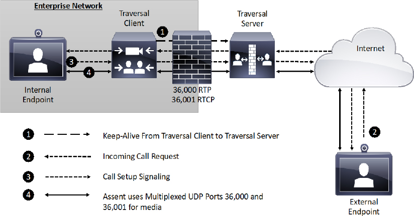
Figure 10-4 Assent Operation for Firewall Traversal
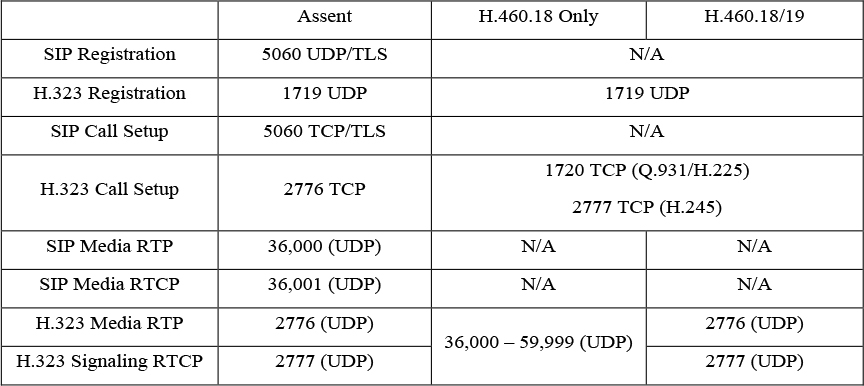
Assent is such a powerful tool, that the ITU used it as the basis to develop H.323 Traversal standards. By summer of 2005 the standards were completed and in full use. H.460.17 was the traversal standard used prior to the Assent-based standards. H.460.17 performs firewall traversal by carrying the media over TCP ports instead of UDP. H.460.18 works just like Assent, except it requires de-multiplexed ports 36,000 to 59,999 to be opened on the firewall. H.460.19 works as a layer on H.460.18 to allow multiplexing the media ports so only two ports need to be opened for RTP and RTCP media streams. In this, H.460.18 and H.460.19 accomplish together what Assent is capable of independently. It is important to note that the ITU standards for firewall traversal only support the H.323 communication standard. Table 10-3 compares all the ports required for Assent to all the ports required for H.460.18/19.
Table 10-3 Ports used with Assent and H.460.18/19
Configuring Traversal Zones on Expressway Core and Edge
When building Traversal Zones between your Expressway Core and your Expressway Edge, it is best practice to configure the Expressway Edge first. This is not a requirement, but the nature of how these servers communicate will warrant a faster initial connection if this procedure is followed accordingly. The Zone on the Expressway Edge will await for a communication from the Expressway Core an infinite amount of time once that Zone is configured. However, the Zone on the Expressway Core will only send a keep-alive message for one-hundred-twenty seconds. If a connection is not established within that time frame, then the server stop sending the Keep-alive messages altogether. If the Zone on the Expressway Core were created first, then this final timeout could occur before the administrator had time to create the Zone on the Expressway Edge. Even if the final timeout had not occurred, an instantaneous connection between the Expressway Core and Expressway Edge is not likely to happen. However, we live in a day and age where we want things to happen instantly. Without that instantaneous result we tend to think something went wrong. If you build the Zone on the Expressway Edge first, then once you create and save the Zone on the Expressway Core, the connection between the two servers is usually instantaneous.
Because we’re talking about firewall traversal, it is necessary to have a secure connection between the Expressway Core and Edge servers, reducing as much as possible the ability for any other server to mimic that communication. Therefore, before you create the Traversal Server Zone on the Expressway Edge you must first create authentication credentials that the Expressway Core will use to authenticate the connection between the two nodes. This is the same authentication process used with endpoint registration, which was discussed in Chapter 6, “Registration on Cisco Expressway”. Traversal Zones always require authentication, so no setting exists that enables authentication for this process; it is enabled automatically. Since the Expressway Edge is acting as the Traversal Server, it will do the authenticating. Therefore, these credentials should be configured in the authentication database on this server. Keep in mind that both the Name and Password settings you create for authentication are case sensitive. Pay attention to syntax because they must match exactly when configured in the Traversal Client Zone on the Expressway Core. The following steps explain how to configure the authentication credentials.
Step 1. Log into your Expressway Edge, and then navigate to Configuration > Authentication > Devices > Local Database.
Step 2. Click New and enter the following information:
a. Name: Create a username that will be used for this Traversal Zone relationship
b. Password: Create a corresponding password for the previously created username
Step 3. Click Create Credential.
Once these authentication credentials have been created, the next step is to create the first Zone. The Zone type to choose on the Expressway Edge for this type of deployment is the Traversal Server Zone. Other options include the Traversal Client Zone and the Unified Communications Traversal Zone. For this deployment scenario the Traversal Client Zone with be used on the Expressway Core. There is a scenario where you may want to configure a Traversal Client Zone on the Expressway Edge, but that scenario will be discussed further in the next section of this chapter. The Unified Communications Traversal Zone is used for Mobile Remote Access (MRA) deployments, which will be discussed in Part 2 of this book. The following steps explain how to configure a Traversal Server Zone on the Expressway Edge.
Step 1. From the web interface of the Expressway Edge, navigate to Configuration > Zones > Zones.
Step 2. Click New and configure the following fields:
a. Name: Provide a logical name for the Zone you’re creating.
b. Type: Traversal Server
c. Hopcount: 15 (default value)
The three previously mentioned settings are all that will display at first, because additional menu options are based on the Zone Type that’s selected. Once you choose Traversal Server as the Type, the following menu options will appear. Continue to configure these settings as described:
d. Connection credentials > Username: Specify the “Name” you configured in the authentication database.
Syntax matters as much here as it does when the credentials were created. Notice you are only configuring the username and not the password. That’s because the password already exists in the database. Specifying the username ties that username to this Zone specifically. If credentials were used on the Traversal Client Zone that exist in the database on the Expressway Edge, but the username was not specified here, then authentication would fail resulting in the Traversal Zones being inactive. This provides another layer of security between the Expressway Core and Expressway Edge. Under the Password menu option, you will see a link entitled “Add/Edit local authentication database”. If you forgot to create the authentication credentials, or if you want to modify the credential, clicking on this link will bring up a pop-up window to the credential database. This way, you do not loose where you are in creating this Traversal Server Zone.
e. H.323 > Mode: On (default) You can disable this service if you know H.323 will not be used.
f. H.323 > Protocol: Assent (default) You can change this value to H46018 per your preferences.
g. H.323 > Port: 6001 (default)
This is the listening port used to maintain the H.323 connection between the Expressway Core and Edge servers once active. This setting is generated by the Expressway automatically and is set to 6001 for the first Traversal Server Zone you create. Should you create more than one Traversal Zones, each subsequent Zone you create will use the next number in sequential order. You can change this port number to any number between 1024 and 65534, but whatever number you use must be configured on the Traversal Client Zone to match.
h. H.323 > H.460.19 demultiplexing mode: Off (default) This setting should only be enabled if the Protocol is changed to H46018 and if you want to use the multiplexing mode. Figure 10-5 illustrates this first set of settings for the Traversal Server Zone.
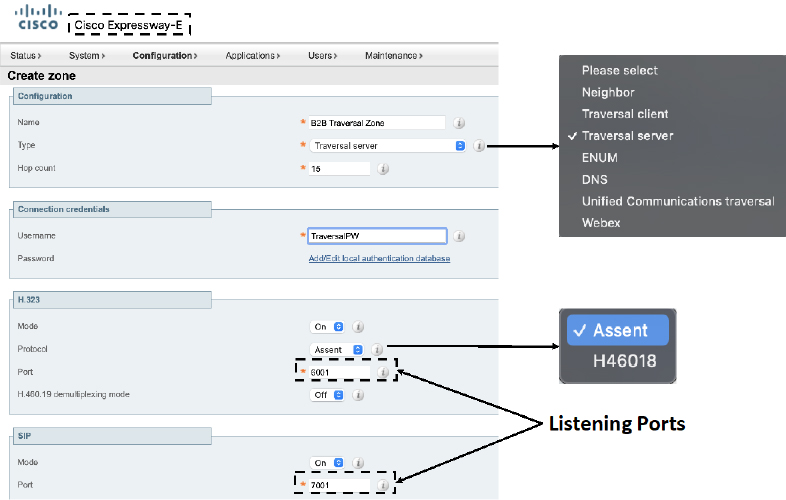
Figure 10-5 Connection Credentials and H.323 Settings for a Traversal Server Zone
i. SIP > Mode: On (default)_
j. SIP > Port: 7001 (default) This is the listing port for SIP. The same rules apply as previously described for the H.323 port.
k. SIP > Transport: TLS (default)
l. SIP > TLS Verify Mode: Off (default) only enable this setting if certificates are being used to mutually authenticate the Expressway Core and the Expressway Edge. TLS Verify is synonymous with Mutual TLS.
m. SIP > Accept Proxied Registrations: Allow (default) This setting is dependent on other settings in the Expressway.
n. Media Encryption Mode: Auto (default)
o. ICE support: Off (default)
p. ICE Passthrough support: Off (default)
q. Multistream mode: On (Default)
r. SIP Poison mode: Off (default)
s. Preload SIP routes support: Off (default)
t. SIP parameter preservation: Off (default)
u. AES GCP support: Off (default)
v. SIP UPDATE for session refresh: Off (default)
Obviously, there are a lot of settings that pertain to SIP. I have included some instruction as to how each of these settings should be configured, however, most of these settings can be left at their default values for a basic Traversal Server Zone configuration, as is being described here. Figure 10-6 illustrates the previously described SIP settings on a Traversal Server Zone.
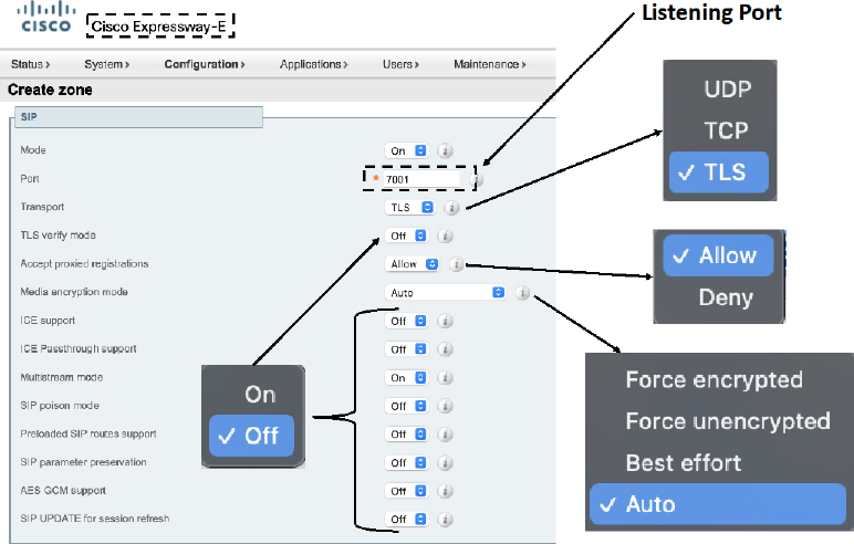
Figure 10-6 SIP Settings for a Traversal Server Zone
w. Authentication > Authentication policy: Do not check credentials (default) Remember that authentication must occur with Traversal Zones no matter what. Therefore, this setting has nothing to do with whether the Zone will use authentication to establish a connection. This setting has to do with how traffic across this Zone will be treated. Use the same standard to set this setting as described in chapter 6.
x. UDP/TCP probes: There are six probe settings, three for UDP and three for TCP. These have to do with keep-alive messages sent between the client and server Zones (UDP), and keep-alives for call setup to keep the firewall’s NAT bindings open (TCP). There is no reason to change these settings, so leave them at their default values.
Step 3. Click Create zone to complete the Traversal Server Zone configuration.
Notice that there is no place to enter the address of the Expressway Core. This is because the Expressway Edge, which lives outside the firewall, will never be able to initiate a communication to the Expressway Core, which lives inside the firewall. However, when the Expressway Core does initiate a communication with the Expressway Edge the Core server address will be provided to the Edge at the same time. Once the connection is saved, the web portal will return you to the main Zones page. You should see a line item for the Zone you just created, and the status for both H.323 and SIP will show On (no active connections). This is the indication I mentioned at the beginning of this section that the Expressway Edge is waiting for a communication from the Expressway Core. This status will persist as it is seen, unchanging, until the Expressway Core established a successful connection to the Expressway Edge. Figure 10-7 illustrates the final setting that need to be configured on the Traversal Server Zone and the saved Zone results from the Zones page.
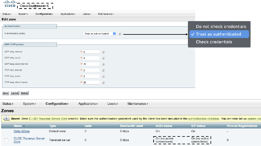
Figure 10-7 Authentication Settings and Saved Results for a Traversal Server Zone
There is still one final step that must be completed on the Expressway Edge to complete the configuration. Remember that anytime you create a Zone of any type on an Expressway, you must also create at least one corresponding Search Rule, or else the Zone can never be searched. Search Rules are configured the same way for Traversal Zones as they are configured for any other Zone. Review the information from Chapter 9 pertaining to Search Rules if you need a refresher on how to configure them.
Once you have finished configuring the Traversal Server Zone on the Expressway Edge, you can now turn your attention to configuring the Traversal Client Zone on the Expressway Core. Use the following steps to configure this Zone.
Step 1. Log into the Expressway Core, and then navigate to Configuration > Zones > Zones.
Step 2. Click New and enter the following information:
a. Name: Provide a logical name for the Zone you’re creating.
b. Type: TraversalClient
c. Hop count: 15 (default)
There are only two types of Traversal Zones available on the Expressway Core. There is a Unified Communications Traversal Zone, which is used for MRA, and then there is the Traversal Client Zone, which you will use in this type of deployment. The Expressway Core cannot ever act as a Traversal Server; therefore, the Traversal Server Zone is not available on this server. Similar to the Zone creation on the Expressway Ede, only the first three configuration options will appear until the Type is selected. Then the following configuration options will appear.
d. Connection credentials > Username: Enter the name configured in the authentication database on the Expressway Edge
e. Connection credentials > Password: Enter the password configured in the authentication database on the Expressway Edge
f. H.323 > Mode: On (default)
g. H.323 > Protocol: Assent (default) You can change this setting to H46018, but notice there is not an H.460.19 option. This part of the ITU protocol is only configured on the Expressway Edge.
h. H.323 > Port: Be sure to use the H.323 listening port number that you configured on the Traversal Server Zone on the Expressway Edge. Figure 10-8 Illustrates the initial configuration settings on the Expressway Core for the Traversal Client Zone.

Figure 10-8 Connection Credentials and H.323 settings for a Traversal Client Zone
i. SIP > Mode: On
j. SIP > Port: Use the same SIP listening port number that you configured while building the Traversal Server Zone on the Expressway Edge.
k. All remaining SIP settings are the same as previously described under the Traversal Server Zone configuration steps. These settings should be configured the same way on the Traversal Client Zone.
l. Authentication > Authentication Mode: Do not check Credentials (default) Again, configure this setting per your environment and as to how you want devices using this Zone to be treated. This setting does not have anything to do with the authentication that must be setup between this Zone and the Traversal Server Zone.
m. Client settings > Retry interval: 120 (default) This is the time parameter mentioned at the beginning of this section whereby the Expressway Core will attempt to establish a connection with the Expressway Edge through the Traversal Client and Server Zones.
n. Client settings > Disconnect on fail interval: 0 (default) This setting defines the number of times the Retry interval will attempt to establishing a connection before it stops trying.
o. Location > Peer <1-6> address: This is where you would configure the IP address or URL of the Expressway Edge. There are six Peer addresses, but peer address 2-6 should only be used when traversing to a cluster of Expressway Edges. Clustering will be covered more in Chapter 11.
Step 3. Click Create zone. This takes you back to the main Zones page. The Zone that you created should show as Active. Figure 10-9 illustrated the Location settings for the Traversal Client Zone and the active connection after the Zone is saved. Bear in mind that this figure shows H.323 as disabled so only SIP will show up as Active.
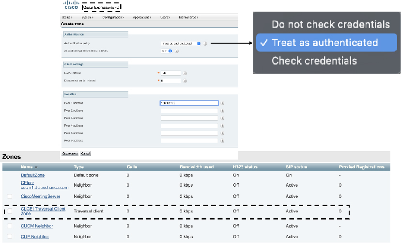
Figure 10-9 Location settings and an Active Status for a Traversal Client Zone
As with any Zones created on the Expressway servers, the final step is to create at least one Search Rule on the Expressway Core for the Traversal Client Zone. Refer to Chapter 9 for a refresher on configuring Search Rules should you need it. Your traversal configuration on the Expressway Core and Edge servers is complete. Before using this solution in a production environment, it is prudent to test calls in both directions first to ensure the network is behaving as it should. If calls fail, or if you experience one-way audio and one-way video then you should check the appropriate ports are open on the firewall.
Deployment Scenarios for Traversal Zones
Up to this point I covered the basic mechanics of creating Traversal Zones on Expressway servers. However, different networked environments require different techniques be used to successfully and securely traverse into and out from these networks. One network component that many companies incorporate into their network topologies to add another layer of security is a Demilitarized Zone, or DMZ. The DMZ is a perimeter network that exists outside an organization’s main corporate network, which acts as a buffer for services that are public facing, such as the expressway edge. Therefore, the Cisco Expressway solution supports several deployment scenarios for networked environments that utilize the DMZ.
In a deployment scenario where a DMZ exists between two firewalls there is a way to route traffic through an Expressway Edge located within this DMZ. This Single Subnet DMZ scenario involves using a single LAN interface with static NAT. In this scenario, firewall A can route traffic to firewall B and vice versa. The Expressway Edge allows video traffic to be passed through firewall B without pinholing firewall B from outside to inside. The Expressway Edge also handles firewall traversal on its public side. Figure 10-10 illustrates the single subnet DMZ deployment scenario.
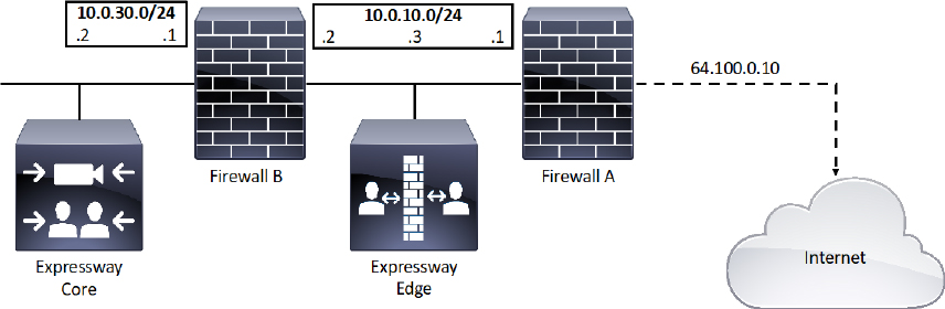
Figure 10-10 Single Subnet DMZ Deployment Scenario
The name of this deployment scenario is after the single subnet that exists within the DMZ. Notice in Figure 10-10 that this subnet consists of an internal interface for firewall A with the IP address of 10.0.10.1, and an external interface for firewall B with an IP address of 10.0.10.2. There’s also a LAN interface for the Expressway Edge with an IP address of 10.0.10.3. The LAN subnet for the internal corporate network includes an internal IP address for Firewall B of 10.0.30.1 and a network address for the Expressway Core of 10.0.30.2. A static 1:1 NAT has been configured on firewall A, NATing the public address 64.100.0.10 to the LAN address of the Expressway Edge. Within the Expressway Edge web interface, Static NAT mode is enabled for the LAN the Expressway Edge is on, with the same static NAT address of 64.100.0.10. This means that the Traversal Client Zone configured on the Expressway Core should have the 64.100.0.10 address configured as the Peer 1 address. However, the Expressway Edge should use 10.0.10.1 as the default gateway address in the network settings. The 10.0.10.3 address is used exclusively for management.
Similar to the single subnet DMZ deployment scenario is the three-port firewall DMZ deployment using a Single Expressway Edge LAN interface. Although both scenarios use a single interface on the expressway E, the three-port firewall DMZ uses three ports on a single firewall to create two subnets. The first interface is used to create a DMZ subnet of 10.0.10.0/30. The DMZ interface on the firewall should be configured as 10.0.10.1 and the interface for the expressway Edge should be configured as 10.0.10.2. The second interface on the firewall is used to create the internal LAN subnet of 10.0.30.0/24. The LAN interface should be configured as 10.0.30.1, and the Expressway Core should be configured as 10.0.30.2. The third interface is configured with the public IP address of 64.100.0.10 for public internet access. A static 1:1 NAT has been configured on the firewall, NATing the public address 64.100.0.10 to the LAN address of the Expressway Edge. Static NAT mode on the Expressway Edge is enabled for the LAN with a static NAT address of 64.100.0.10. The Expressway Edge should be configured with a default gateway of 10.0.10.1. Since this gateway must be used for all traffic leaving the expressway edge, no static routes are needed in this type of deployment. Again, the Traversal Client Zone on the Expressway Core should be configured with a Peer 1 address of 64.100.0.10. Figure 10-11 illustrates the three port firewall DMZ deployment scenario.

Figure 10-11 Three Port Firewall DMZ Deployment Scenario
Neither the single subnet DMZ deployment, nor the three port firewall DMZ deployment scenarios are recommended by Cisco for a production environment. For all the deployments that use only one Network Internet Card (NIC) on the Expressway Edge, but also require static NAT for public access, the media must “hairpin” or reflect on the external firewall whenever media is handled by the Expressway Edges Back-to-Back User Agent (B2BUA). In these deployments the B2BUA sees the public IP address of the Expressway Edge instead of its private IP address, so the media stream must go through the network address translator to get to the private IP address. Not all firewalls will allow this reflection, and it is considered by some to be a security risk. Each call where the B2BUA is engaged will consume three-times as much bandwidth as it would using the recommended dual NIC deployment. This could adversely affect call quality.
This brings us to the dual NIC DMZ deployment scenario, which is the method Cisco recommends using for most DMZ deployments. This deployment requires the advanced networking option key be installed on the Expressway Edge that lives within the DMZ. This option key enables the use of two NICs on the Expressway Edge to connect to two autonomous networks. This option key comes as a $0.00 item with the purchase of a basic license package for Expressway series, but it can only be installed on the Expressway Edge. The Expressway Core will not support the Advanced Networking option key. Figure 10-12 illustrates the Dual NIC DMZ deployment scenario.
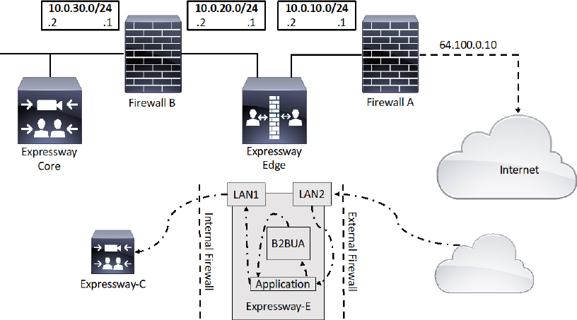
Figure 10-12 Dual NIC DMZ Deployment Scenario
In a dual NIC deployment, configure the External LAN interface setting on the IP Configuration page to be LAN2. This setting determines where the Expressway Edge TURN server allocates Turn relays. If any routers are being used within your network that support Application Layer Gateways (ALGs), be sure to disable the settings for SIP and H.323. The Cisco Expressway solution does not support this functionality on firewalls when deploying the Expressway Edge behind a NAT. The Expressway Edge must perform the static network address translation on its own Interface. The LAN1 and LAN2 interfaces must be located in non-overlapping subnets. This will ensure traffic is sent through the correct interface. Figure 10-11 illustrates how this solution should be deployed. In a typical DMZ deployment the internal firewall and external firewall cannot route directly between one-another. Therefore dual-NIC devices, such as the Expressway Edge, are required to validate and forward the traffic between the isolated subnets. This is the security of this solution. No traffic can pass through the network without traversing through the Expressway Edge. The Expressway Edge will only allow voice and video signaling and media through, so hackers will have to find another path into the network. The outward facing interface on the Expressway Edge, LAN2, has static NAT configured. The Traversal Client Zone on the Expressway Core will point to the internal facing interface on the Expressway Edge, LAN1, using the address 10.0.20.2.
One final deployment scenario for traversal zones through a DMZ that is worth mentioning involves an Expressway Core that exists inside the corporate network, an Expressway Edge that exists in the DMZ and a second Expressway Edge that exist on the network edge outside the DMZ on the public-facing side. The Public-facing Expressway Edge should be configured with a Traversal Server Zone. The Expressway Edge that exists inside the DMZ is configured with a Traversal Client Zone pointing to the IP address of the public facing Expressway Edge. The Expressway Edge that exists in the DMZ is also configured with a Traversal Server Zone. The Expressway Core that exists within the corporate network is configured with a Traversal Client Zone that points to the Expressway Edge in the DMZ. In this manner, the two firewalls never talk to one-another, so the security from the Dual NIC DMZ deployment scenario is still in play. Additionally, TURN is not required to achieve access through the external firewall, so there is a higher level of security where this firewall is concerned. The downside to this deployment scenario comes with the cost of supporting a third Expressway. Additionally, MRA cannot be supported though this type of deployment either. For these reasons, most corporations will not use this deployment scenario. However, networked environment that require the highest level of security, such as with government and military, this is the only approved deployment solution for firewall traversal. Figure 10-13 illustrates the triple Expressway deployment scenario.
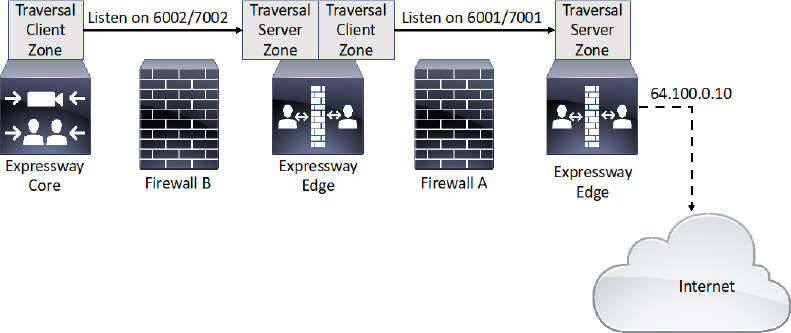
Figure 10-13 Triple Expressway Deployment Scenario
DNS Zones
Another Zone type that can be used on the Expressway Series is the Domain Name System (DNS) Zone. This Zone type allows the Expressway to query a DNS for domain lookup. Due to the nature of how DNS works, and where DNS servers typically live within an enterprise network, there are two applications through which DNS Zones can be used within a Cisco collaboration solution. DNS Zones can be used to route calls between Expressways within an enterprise network. DNS Zones can also be used to route calls between corporations through the public internet space.
Chapter 9 discussed the use of Neighbor Zones to route traffic between Cisco Expressways. The Complex Video Network with a Hierarchical Dial Plan was also discussed during that chapter as an efficient method of routing calls across an enterprise network. In a similar fashion to the Hierarchical Dial Plan using Neighbor Zones, DNS Zones can be used to route calls between Expressways within an enterprise network. An advantage to using DNS Zones versus using Neighbor Zones is that the number of Zones needed to support this solution is greatly reduced by leveraging DNS. A potential disadvantage to using DNS Zones is that DNS only allows for URI dialing. Figure 10-14 illustrates what a network topology would look like when DNS Zones are used for internal dialing.
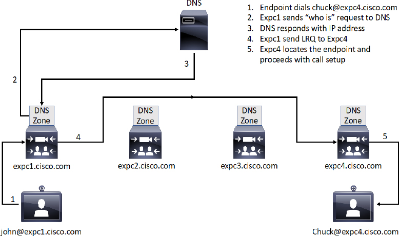
Figure 10-14 DNS Zones used for Internal Call Routing
Based on the scenario outlined in Figure 10-14, the endpoint on the left dials [email protected] and sends the call request to its local Expressway Core, which is expc1.cisco.com for this example. Like all other Zone in an Expressway, DNS Zones need Search Rules too. Based on the Search Rule configured for the DNS Zone, this expressway knows it needs to query the DNS server before proceeding with the call setup. So, expc1.cisco.com sends a “Who is” request to the DNS server to find the location of expc4.cisco.com. Notice that the query to the DNS server is not for [email protected]. The query is only for the domain part of the URI, which is expc4.cisco.com. The DNS server will look up the A-record for expc4.cisco.com in order to discover the associated IP address, and then will return this information to the requesting server. Now that the Expressway has the IP address of the destination server, it will send an LRQ to the destination IP address searching for [email protected]. Since this Expressway is able to locate the endpoint using this alias, the call setup will continue so that John and Chuck can communicate with one-another.
Notice that the alias used for DNS dialing is a URI address, which resembles an email address. With SIP this is an organic method of dialing because the SIP URI is already in the proper format for dialing using DNS. With H.323, the H.323 ID should be used in the form of a URI, or else Transforms should be used to format aliases appropriately.
ENUM Zones on the Cisco Expressway work on the same principle as DNS Zones. ENUM stands for Enumerated dialing, or E.164 Number Mapping. It is a way of using DNS Name Authority PoinTeR (NAPTR) records to convert E164 numbers into routable URIs. ENUM is defined in RFC 3761. A DNS server must be configured with NAPTR records that do the following:
![]() Define (using Regular Expressions) how a presented E.164 number is converted to a routable URI.
Define (using Regular Expressions) how a presented E.164 number is converted to a routable URI.
![]() Defines the transport protocol to be used for the call, such as SIP or H.323.
Defines the transport protocol to be used for the call, such as SIP or H.323.
Therefore an E164 alias such as 25677809 could be translated to SIP:[email protected] or H323:[email protected]. The NAPTR record needs to exist in the name server that is specified in the DNS Suffix, such as enum.search.com. When searching an ENUM zone, the Expressway will transform an E164 alias from 1234 into [email protected]. This alias is looked up as a DNS lookup, and the enum.org server will reply with a service and a URI. The URI can then be contacted through a DNS lookup.
There are three settings that must be configured on the Cisco Expressway before DNS Zones can be used. Obviously, you must configure a DNS Zone and at least one Search Rule. However, the third setting that must be configured are the actual DNS settings. The settings are not configured in the DNS zone as you might think they should be. The DNS server address and Expressway URL are settings that need to be configured under the Systems menu of the Cisco Expressway. To create a DNS zone and configure the DNS settings, follow these steps:
Step 1. Log into the Cisco Expressway and navigate to Configuration > Zones > Zones.
Step 2. Click New and configure the following information:
a. In the Name field, enter the name of the DNS zone you are creating.
b. In the Type field, select DNS as with other Zones, this will expand the menu options based on the Zone Type you selected.
Step 3. Notice that the menu options are quite different than other Zones you have created on the Expressway. There is no place to enter the DNS server address, and little other options that can be configured at all. Leave all the settings at their default values, and click Create zone, which is located at the bottom of the page.
Step 4. Create the appropriate search rules after the zone creation is complete. Figure 10-15 illustrates the Menu options for configuring DNS Zones on the Cisco Expressway.
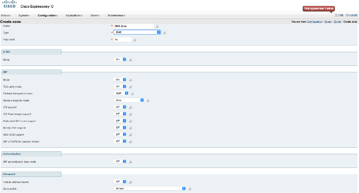
Figure 10-15 DNS Zone Menus on Cisco Expressway
To configure DNS settings on the Cisco Expressway, follow these steps:
Step 1. Navigate to System > DNS
Step 2. In the System host name field, enter the host name as it appears in the DNS.
Step 3. In the Domain name field, enter the domain name as it appears in the DNS.
Step 4. In the Address 1 field, enter the IP address of the DNS. You can enter up to 5 DNS addresses here. There is also a section at the bottom of this page where you can enter a different address for up to five unique domains.
Step 5. Click Save once you have configured all the appropriate fields. Figure 10-16 illustrates the DNS settings on a Cisco Expressway.

Figure 10-16 DNS Settings on Cisco Expressway
All the settings I just covered on the Cisco Expressway will only get a “Who is” request to the DNS server. There are still settings that must be configured on the DNS so that URI addresses can be resolved to IP addresses. If you are only planning to use an internal DNS to route calls between Expressway Core servers, then the only DNS record you need to create is an A-record. A-records are the most basic type of any DNS records. They are simply a mapping of a domain or subdomain to an IP address. The following is an A-record example, where Target is an A-record defining the destination:
Host Domain URL (DNS puts them together) IP address
expc1 cisco.com expc1.company.com 10.1.1.40
There are a multitude of DNS servers on the market today that can be used to host these services. Although the basic elements of an A-record are the same, how you configure these settings will depend on the model of the DNS server being used. For the purpose of this book, I will show you how to create a DNS A-record using the Microsoft DNS service running on a Microsoft Windows Server 2012 R2 Standard platform. Note that DNS is a service that runs on the server, and as such it must be enabled and configured prior to creating any address records of any type. This book will not go into how to initially configure any part of a Microsoft Windows Server. Use the following steps to configure A-records on a Microsoft DNS.
Step 1. Begin by opening the Server Manager, and then navigate to Tools > DNS.
Step 2. Depending on how DNS was setup to begin with, there may be several folders in the hierarchical tree structure. Right-click on the folder you want to create the A-record in and select New Host (A or AAAA)…
Step 3. In the popup window enter the following information:
a. Name (uses parent domain name if blank): This is the Host part of the URL specified previously.
b. Fully qualified domain name (FQDN): This is the full URL, and this field is automatically populated. Notice there is nowhere to enter the Domain. That’s because the folder this A-record is being added to already operates under a specific domain.
c. IP address: This is the IP address of the server to which the URL will map.
d. Create associated pointer (PRT) record: Check this box if you want the DNS server to create a reverse DNS record, or pointer record, in association with this A-record. Generally, it is a good idea to check this box.
e. Allow any authenticated user to update DNS records with the same owner name: For security reasons, you probably do not want to check this box. Only administrators should be allowed to update DNS records.
Step 4. Click Add Host to complete the creation of this A-record. Figure 10-17 illustrates the fields used to create an A-record in a Microsoft DNS server.
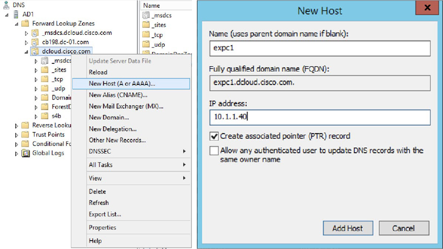
Figure 10-17 Creating A-Records on a Microsoft DNS Server
In order for locally registered endpoints to be reached via DNS routing, the dialed alias must be in the form of a URI. The easiest way to achieve this outcome is to have both SIP and H.323 endpoints register using a URI, otherwise they will only be discoverable by the local Expressway to which they are registered. H.323 endpoints should register with the Expressway using an H.323 ID in the form of a URI address in order to be reachable via DNS routing. SIP endpoints always register with an Address-on-Record (AOR) in the form of a URI, so no change is needed for these aliases.
An alternative solution would be to create transforms on the search rule for the DNS Zone that changes aliases to a full URI if they are not already in that form. Additional Transforms must also be configured to strip domains from a URI for incoming calls. The interworking Transform and Search Rule, which was explained in Chapter 7, “Configure Expressway Core Dial Plan Elements,” could be implemented to prevent the need for H.323 IDs to take the form of URI addresses. E.164 aliases could be dialed through DNS as well, as long as the source endpoint originally dialed E.164@domain.
The other application for using a DNS Zone in a Cisco collaboration solution centered around the Expressway series is to use it for B2B or B2C communication. This is the more common application to how DNS is used in a current Cisco Collaboration solution. Where an internal DNS server is used for routing within an enterprise network, a public DNS must be used for routing across the public internet. Internal routing can be achieved by simply creating an A-record as previously explained, but routing across the public internet requires both an A-record and Service Records (SRV). The DNS SRV response is a set of records in the following format:
_ service. _ protocol.<fqdn>. TTL Priority Weight Port Target
_sip._tcp.company.com 7200 20 5 5060 vcs1.company.com
An SRV record is primarily used to handle incoming service requests over specific ports. If both SIP and H.323 are being used, an SRV record must be created for every port that is associated with these two protocols. H.323 uses UDP port 1719 and TCP port 1720. SIP uses UDP port 5060, TCP port 5060, and TLS port 5061. Therefore 5 SRV records will need to be created. The format of DNS SRV queries for SIP and H.323 used by Expressway are:
_sips._tcp.<fully.qualified.domain>
_sip._tcp.<fully.qualified.domain>
_sip._udp.<fully.qualified.domain>
_h323ls._udp.<fully.qualified.domain> —for UDP RAS messaging, for example: LRQ
_h323cs._tcp.<fully.qualified.domain> —for H.323 call signaling
When configuring TLS for SIP, the service and protocol can be configured two ways:
![]() sip._tls.
sip._tls.
![]() sips._tcp.
sips._tcp.
Within an enterprise network where DNS is used for B2B and B2C calling, DNS zones and DNS Servers should only be configured on the Expressway Edge. DNS A-records should be configured on a public DNS using the IP address and URL of the Expressway Edge as the authoritative proxy for the enterprise. Figure 10-18 illustrates a network setup for B2B communications using a DNS Zone on the Expressway Edge.
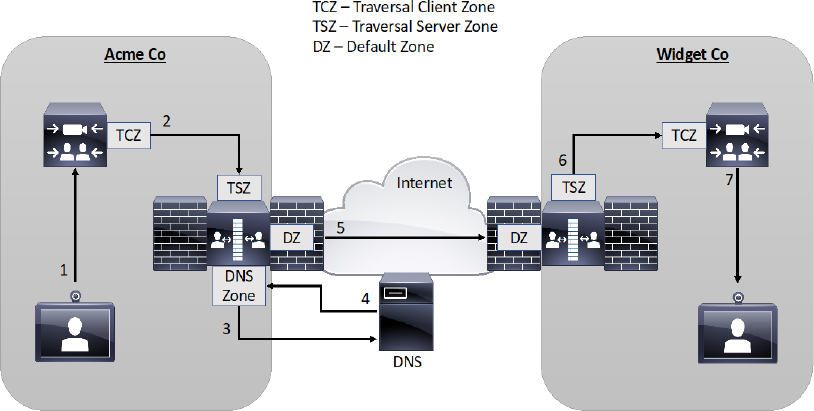
Figure 10-18 DNS Zone used for B2B Communication
Exam Preparation Tasks
As mentioned in the section “How to Use This Book” in the Introduction, you have a couple of choices for exam preparation: the exercises here, Chapter 24, “Final Preparation,” and the exam simulation questions in the Pearson Test Prep Software Online.
Review All Key Topics
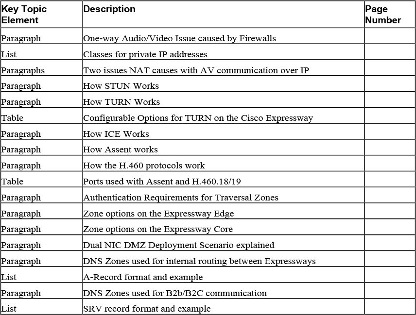
Review the most important topics in this chapter, noted with the Key Topics icon in the outer margin of the page. Table 10-4 lists a reference of these key topics and the page numbers on which each is found.
Table 10-4 Key Topics for Chapter 10
Complete Tables and Lists from Memory
Print a copy of Appendix C, “Memory Tables” (found on the companion website), or at least the section for this chapter, and complete the tables and lists from memory. Appendix D, “Memory Tables Answer Key,” also on the companion website includes completed tables and lists to check your work.
Define Key Terms
Define the following key terms from this chapter and check your answers in the glossary:
Application Layer Gateway (AKG)
Back-to-Back User Agent (B2BUA)
Interactive Connectivity Establishment (ICE)
Internet Protocol version 4 (IPv4)
Internet Protocol version 6 (IPv6)
Name Authority Pointer (NAPTR)
Network Address Translation (NAT)
Port Address Translation (PAT)
Session Traversal Utilities for NAT (STUN)
Traversal Using Relays around NAT (TURN)
Q&A
The answers to these questions appear in Appendix A. For more practice with exam format questions, use the Pearson Test Prep Software Online.
1. List the three classes of private IP addresses with the IP ranges.
2. List all the components (broad scope) that must be configured on the Expressway Core and Edge servers to support a firewall traversal connection.
3. List the A-Record format with an example and the SRV formats with examples for SIP and H.323.
Answers
1. Private IP address classes
a. Class A addresses: 10.0.0.0 – 10.255.255.255
b. Class B addresses: 172.16.0.0 – 172.31.255.255
c. Class C addresses 192.168.0.0 – 192.168.255.255
2. Traversal Zone components
a. Expressway Core
i. Traversal Client Zone
ii. Search Rule(s)
b. Traversal Server Zones
i. Authentication Username and Password
ii. Traversal Server Zone
iii. Search Rules(s)
3. A-record and SRV record formats
a. _ service. _ protocol.<fqdn>. TTL Priority Weight Port Target
b. _sip._tcp.company.com 7200 20 5 5060 vcs1.company.com
c. _sips._tcp.<fully.qualified.domain>
d. _sip._tcp.<fully.qualified.domain>
e. _sip._udp.<fully.qualified.domain>
f. _h323ls._udp.<fully.qualified.domain> —for UDP RAS messaging, for example: LRQ
g. _h323cs._tcp.<fully.qualified.domain> —for H.323 call signaling