

CHAPTER 3
Studio Setup

The best recordings come from properly designed spaces. Before anything is loaded into the room, before any equipment setup begins, you must determine the best ways to take advantage of the recording space. Some studios have dead areas and live areas, each with their individual functions. Some studios have adjustable wall panels that can liven or deaden areas of the room. You may decide to, for example, record horns in a live area of the room and record an intimate acoustic guitar in a less live area.
Again, understanding the physical limitations and characteristics of the room helps you decide where each setup will sound best.
Room Preparation
• Clean the place. A clean studio, as with a clean control room, keeps everyone from getting anxious. It makes you look like a professional, not some hack that doesn't care enough to clean out the dirty food containers.
• Use it or lose it. Remove everything that isn't involved in your session, such as another client's equipment. Every item in the room rattles, so, if it isn't there, that's one less rattle to worry about. In addition, when the client books the studio, he wants the whole studio. It isn't fair to him when you store someone else's equipment in the corner of the room.
• Go ahead and ask. In an unfamiliar studio, ask a staff member about any standard instrument placements. Then use that information, along with your experience, when placing each instrument. Sketch the layout of the studio and use it to decide where each instrument will go.
• Deal with noisy floors and chairs. Oil squeaky chairs and throw down a carpet over squeaky floors. Everyday noises that are unconsciously blocked out by our ears are not blocked out by the microphones.
• Diffuse the situation. Use diffusion devices, such as sections of acoustic foam, stand-alone baffles, and perhaps sections of plywood placed on the floor to fit your specific session needs. Figure 3.1 shows how properly placed baffles will block and absorb most initial reflections. In this instance, reflections coming back off the wall are not an issue. Baffles might be used as absorption devices or reflective devices, depending on the situation. Note that absorption devices do not affect some frequencies, such as low lows.
• Any size recording studio can make hit records. Good equipment means nothing unless the players are up to the task. Thinking you will get a great recording because you use the best gear is like thinking you can do a great painting because you have the best paintbrushes. Even a broken pencil can draw a masterpiece.
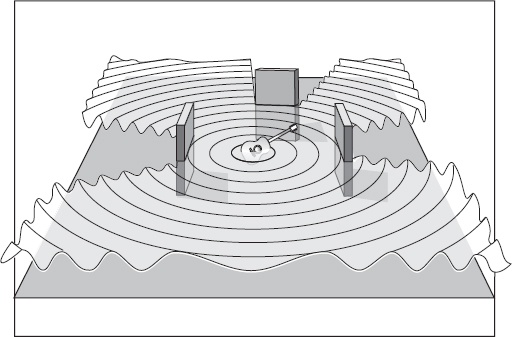
FIGURE 3.1
Baffles used for absorption
Placement
• Draw a setup sheet with the layout of the room. Before considering where the instruments and players are placed, draw an instrument setup sheet, along with an input list, to refer to. This is useful when other people are helping to set up the room.
• How many players are recording basic tracks? Most recordings are broken down into three sections: basics, also called bed tracks, then overdubs and mixing. In today's studio, these overlap considerably. Determine how many players will be in the studio during the basics to properly choose which, and how many, microphones to use on each setup. Different situations will require different approaches.
• What is the style of music? Determine player placement by considering the style of music, how prominent each instrument will be, and how many players there are. Is it:
- A jingle? Jingles are advertisements heard on radio and television – often 30 or 60 seconds long. Recording will often be completed in a single day so there will not be a lot of time for experimentation. The most important factor here is usually the time restraints. Because the musicians that play on jingles are professionals, they will most likely play the part properly every time. The emphasis here is not on setup or performance. It is assumed that the setup is good and that the performance will be fine. The important factors here are time and money. Set up and press the record button. Proper documentation is key for a smooth-running jingle session. Many different versions of a commercial, or ‘spot,’ are recorded, and each spot needs proper documentation during recording, editing, and mixing.
- A movie soundtrack? As movies get cheaper and more accessible, more engineers are getting into recording movie soundtracks. While most modern records are recorded to feature vocals or a certain instrument, movie soundtracks are less focused on the individual player and more on creating a feel that complements the movie. There is no strict standard, and you would record what each scene requires: a large group of players or an individual musician.
- A power rock band? They might sound better in a larger live space. Start the session by concentrating on bass and drums, but also record reference vocals and guitars.
- A jazz session? You may prefer a mellower, dryer feel from a less reverberant space. With jazz, often players will want to watch each other without headphones. Everything is recorded live with no overdubs. Confirm that your session has enough hard drive space, because, left to their own devices, jazz players will never stop playing. Sleep? Food? Time itself? All secondary to the groove.
- A demo? Recording demos is not the time to spend four hours getting that perfect guitar sound. Take less time on setup and more time recording.
- A television show? Many televisions have smaller speakers that cannot recreate a wide range of frequencies. Therefore, a piano, for example, recorded for a television soundtrack might not have the same equalizer setting as a piano recorded for a rock record: on a television soundtrack, boosting low low frequencies might not have much of an effect. They will equalize and compress it at the TV station.
- A rap or hip-hop session? Commonly, electronic drum machines and modern keyboards combine with live vocalists. Vocals might be recorded after all the music is recorded. To play off of each other, sometimes two or more singers record into separate microphones at the same time.
- An independent punk band? They might sound best in a smaller, tighter ‘garage’ style room. Not a lot of setup time, and often raw sounds with live vocals.
- A solo acoustic player/singer? Setup may sound best in a smaller, more intimate space, and the voice and the musical instrument might have separate microphones. The microphones could be placed in a stereo array in front of the artist, as long as they are comfortable.
No matter what the situation, all aspects of the recording, production, and playing must be of the highest quality. The world (hopefully) is going to hear the results, so take the time to set up properly and record everything correctly.
• Places please. Most musicians, if they have been playing together for a long time, get used to certain placement among the rest of the players. Maybe the rhythm guitar player prefers to stand on the left side, while the bassist may like the right. Ask the players if they are used to playing in specific locations in reference to each other, and set them up that way.
• Don't isolate the players. Just because an amplifier is isolated doesn't mean that the player must be isolated as well. Commonly, players being recorded together should be able to see each other, and at least one should be able to see the engineer. The person who can see the engineer normally gets a talkback microphone.
• Carpets and chairs. Before setting up the microphone stands and running the cables, lay out any carpets that will be needed. Tape them to the floor to keep them in place and so no one trips and falls. Once the carpets are down, place chairs for each player. They might not use them when they are actually playing, but they may want to sit down during playback or during a lull in the session.
• Setup and sit down. Bring in and set up the instruments as described in the next few chapters. With the instruments placed according to your setup sheet, begin placing the microphone stands and cables.
Microphone Stands
• Don't use a large boomstand. Sometimes a smaller boomstand will be less obtrusive. Microphone stands can range from a small stand to hold a tiny microphone, all the way up to a large boom with a big microphone hanging off the end of it. Match the stand size with the situation.
Microphone stands touch nothing but the floor. A microphone stand won't tip over unless it was teetering in the first place.
• Use a large boomstand. Larger boomstands tend to be more stable, with less resonances and rattles, and they help eliminate rumble from the floor.
• Stand still, laddie. Today's microphone stands tend to be flimsy, so don't force any of the clasps. Take the time to unscrew the fastener, and set the stand and the arm to the proper placement. Then tighten the clasp. Not Superman tight, but tight enough that the microphone stays at the right spot until the end of the session.
• Duct tape rules. Leave a couple of rolls of duct tape around, but only use it to stop resonance and rattles, not to hold a microphone stand. Duct tape won't hold a microphone stand in place for long, and it looks unprofessional. But sometimes there is no choice. If you must use duct tape to hold anything, don't wrap a whole roll around the microphone stand. A few times around will do.
• Stand up. Place all stands and run all cables before attaching the microphone to the stand. Wheeling a large boomstand around a cluttered room with a microphone connected to it is just asking for damage. Make a habit of setting up microphones last and breaking them down first.
• Secure the boomstand. If you must use a smaller tripod boomstand, place the stand so one leg is directly under the boom, then sandbag the other two legs to keep them secure. Place a sandbag on the base of the stand to ensure stability. If someone bumps into it and it topples over, it's your fault.
• Pair of matching shocks. When setting up to record something in stereo, use matching shockmounts, stands, and microphones. This not only looks professional but also makes both microphones sound alike. If one microphone has a shockmount and the other doesn't, a slight rumble may creep into the one without the shockmount. Then you might need to add a low-end roll-off to one side, thus changing the intended matched sound.
• Weight for the boom. Set the counterweight of larger boomstands high enough so no one hits their head. If someone gets smacked in the nose, it gives the studio a black eye.
Cables
• What are balanced cables? A standard recording studio XLR balanced cable uses three wires – two to carry the signal and one for the shield. The three wires are termed hot, cold, and common. Both XLR and ¼” stereo cables are balanced. On a balanced ¼” cable, the three wires connected are tip, ring, and sleeve (TRS), with the sleeve being the shield terminal.
Figure 3.2 shows the two ends that carry the signal, and one has the polarity (phase) switched. Why? Any interference will affect both wires equally. At the balanced input connector, these equal and opposite interference signals will cancel out. This process is called balancing or common mode rejection. This eliminates interference so you can use longer cables with minimal hum pickup.
• What are unbalanced cables? A standard guitar cord is an example of an unbalanced cable. It contains two wires – one wire is the hot and the other is the shield. The shield is wrapped around the hot wire and used for the return signal. Unbalanced cables are normally used for getting mono signal from the instrument to the amplifier or direct box. Most outboard equipment uses ¼” inputs and all consoles have the option of balanced and unbalanced ¼” (line level) inputs.
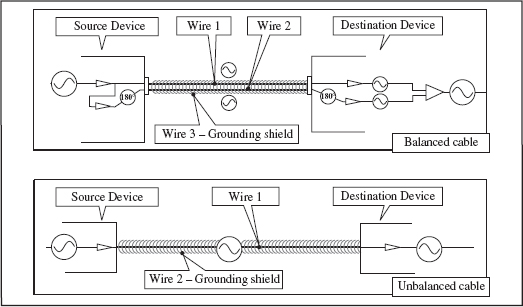
FIGURE 3.2
Balanced and unbalanced
Another unbalanced line is a ¼” non-shielded speaker cable, which is two heavy-gauge parallel wires. Cables from amplifier to speaker must be heavy gauge for as little power loss as possible. Don't use speaker cable in place of shielded cable.
Running cables
• Got cables? Confirm that there are enough cables, including ¼” , XLR, power cables, and AC (alternating current) power boxes. Bring them into the room and set them in their appropriate places.
• Use the proper cable and connectors. Adapters will always degrade the signal so use them as a last resort. For the best results, use the proper cables so no adapters are necessary. Using one long cable is better than joining two short ones together.
• Respect the studio cables. Wrap and unwrap studio cables correctly and don't throw them around. Avoid any sort of sticky tape to hold cables together. Use a specific plastic clip, a Velcro strip, or even a piece of rope with a loop on the end.
• Label the cable. Label both ends of XLR cables for easier tracing. For example, if cable 28 is connected to a microphone that is not working, rather than having to trace it through the labyrinth of all the other cables, simply read the number on the cable then check where the corresponding number is plugged in at the input panel.
• Keep it short. Use the shortest possible unbalanced, high-impedance cables. Longer cables can pick up hum and, as length increases, can diminish high frequencies.
• Keep it long. Allow enough length so cables are never taut. Don't wrap them up in a coil; just leave the excess cable on the floor by the base of the microphone stand.
• Leave a channel or two open when plugging in the drums. You want all the drum microphones to enter the console in the same area. Later in the session, if you need to add another drum microphone for any reason, you won't need to return it somewhere else on the console.
• Use the best cable. Don't use a suspect cable on a microphone. If you're short on cables, use it on headphones. If the cable fails during the session, the recording will not be compromised. No one wants to find out half the piano sound is gone when it comes time to mix. Remove faulty cables from the room so no one mistakes them for usable cables.
• For best results. Use the shortest, thickest, highest quality cables on the vocal microphone.
• Check your shorts. Keep an ohm meter close by to determine where a problem lies. Is the microphone not working? Is there a short in the cable? Maybe it can be as simple as a wrong button pressed at the console. A meter tells you instantly if signal is correctly flowing through a piece of gear.
• Three-cord rock and roll. Place extra everything close by. The session should never stop due to a lack of workable cables.
• Power arrangers. Don't run (high-level) AC power cables parallel with (low-level) audio signal cables. Cross power cables at right angles from signal cables to minimize AC buzz leaking into the microphone cables.
• The wall of sound. To avoid interference, run cables a few inches away from the studio wall. Right behind this wall lies a plethora of power cables and other audio lines.
• Don't plug everything into one AC outlet. You will have a hot, smoking studio with scorching leads and blazing tracks that smolder! Get it?
• Wrap the cable around the stand. If you are sure the microphone stand is properly placed and the signal flow is correct, maybe wrap the cable around the stand to keep it out of the way.
• Don't wrap the cable around the stand. Unwrapping and removing a cable because the placement is wrong is a waste of valuable setup time. Sometimes, just leave it to hang.
Microphones
• What is a microphone? A microphone is a transducer that changes acoustic energy to electrical energy. Sound causes the diaphragm within the microphone to vibrate, creating a small voltage. Louder signals cause the microphone's diaphragm to vibrate more, creating more voltage.
The diaphragm is the internal membrane (or the ribbon – depending on the microphone) within the capsule that vibrates. Different microphones will display different frequency response charts. There is more on this later in this chapter.
A small diaphragm microphone will commonly, but not always, accentuate mid to high frequencies. Due to the smaller mass of the smaller diaphragm, the low frequencies may not be as accurate as in a large diaphragm microphone.
Large diaphragm microphones might offer the widest range of frequency response to capture warmth, as for low strings or vocals. These microphones tend to naturally recreate better low frequencies simply due to the mass of the diaphragm. The larger the mass, the less accurate the transient response.
• Do a listening test. When you understand the characteristics of each microphone, you are better equipped to choose the best microphone for each situation. A listening test will help train your ears to determine which microphone does what. Once trained, you use your ears and your experience to choose the best microphone.
Set up the best few microphones available, perhaps four or five at a time, with the individual capsules adjacent to one another. Use no pads or rolloffs, and match the polar patterns. Set the faders so all the microphones have the same perceived volume. Have someone stand at an equal distance from all microphones and speak or sing. Switch one microphone on at a time and listen to which ones:
- Produce a nice, crisp high end.
- Produce a warmer midrange.
- Retain warmth and smoothness no matter what frequencies are altered. Lower-quality microphones may start to sound brittle as you boost the higher frequencies.
- Have a thick bottom.
- Produce hums or buzzes. Microphones with inherent lower levels may be noisier simply because the level must be raised to match the rest of the microphones being tested. Older tube microphones can have this problem, but their great sound makes up for it.
- Change level uniformly as the person moves about the microphone. Some cardioid microphones are more omnidirectional than others, and some may not be omnidirectional at all frequencies.
• What is the proximity effect? The proximity effect is the increase in a microphone's low-frequency response when it is placed very close to a sound source. Microphones with omnidirectional patterns are not affected by the proximity effect.
• What is phantom power? Condenser microphone capsules are very high impedance, so they need an impedance converter circuit that requires power to operate. The power is called phantom power and it comes from each mixer microphone input. Dynamic microphones have no active electronics, so phantom power is not needed.
• What is a pre-amplifier? Whether inside or outside the console, the microphone pre-amp raises the microphone signal level to a usable ‘line level’
• What does frequency response mean? A device's frequency response is its output level versus frequency. Different microphones will display different frequency response charts. All new microphones come with a response chart. Figure 3.3 gives a readout page that shows that some microphones will have a smooth high end while others may have an upper midrange bump. While these charts may not be readily available for you to refer to, simply listening to different microphones on a similar sound source will result in a general idea of how a microphone's chart would look.
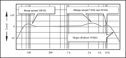
FIGURE 3.3
Microphone frequency response charts
• What does transient response mean? Transients are the initial sudden peaks of a sound, and are very short in duration. Transient response is the measurement of how quickly a device responds to these transients. A percussion instrument contains very high transients, as can vocal sibilance.
• Which microphone is best? The best microphone is the one that sounds best in a particular situation. Unless you are totally familiar with all the microphones at your disposal, the only way to tell is to set up all the available microphones and listen. With experience, you will learn the characteristics of each microphone, and choosing which ones are best for different situations will come naturally. Microphones are the tools of your trade – learn them.
Dynamic microphones
Dynamic moving coil microphones use a coil of wires attached to a diaphragm, which is suspended within a magnetic field (Figure 3.4). Acoustical vibrations cause the diaphragm and the coil to vibrate within this magnetic field, creating current that electrically represents the audio signal.
Dynamic microphones tend to be robust and are commonly used for the close miking of louder instrument setups including guitar amplifiers, drums, and live vocals. Characteristics include a good transient response, a natural midrange peak, (about 5 kHz) solid low-frequency response, and tight polar pattern to keep leakage at bay. Because of their rugged build, dynamic microphones are often used in live situations.
Condenser microphones
Condenser microphones use two adjacent plates. One is stationary, while the other, a diaphragm, vibrates to incoming acoustic signal.

FIGURE 3.4
The dynamic microphone
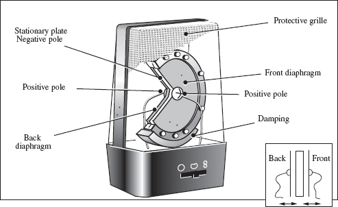
FIGURE 3.5
The condenser microphone
These two plates are charged with a constant voltage called phantom power. As the distance between the diaphragm and the stationary plate varies with incoming vibrations, a varying electrical current is generated (Figure 3.5).
Condensers tend to be less robust than dynamics. They are also usually a bit warmer and smoother and they capture a wide frequency range. They might be used on instrument setups such as vocals, acoustic instruments, room ambiance, and less powerful electric instruments. Because all condenser microphones have a pre-amp, their output voltage is much higher than that of a dynamic microphone.
• What are tube microphones? Standard condenser microphones use internal transistors to pre-amplify the very small electrical current produced by the charged diaphragm. Some condenser microphones use tubes, not transistors. These tube microphones have their own power supply that charges the tube and the diaphragm. Tube microphones are expensive and delicate, but create a super-warm, round sound.
Ribbon microphones
Ribbon microphones use the same principle as dynamic microphones only, rather than a coil of wire, they use a ribbon of metal foil (Figure 3.6). This foil ribbon vibrates within a strong magnetic field, creating a small electric current. This field is strong. Not strong enough to pull your belt off, but maybe strong enough to erase a tape, if left too close. Keep your tapes and drives away from ribbon microphones.
Ribbon microphones traditionally record wonderfully lush low end and sound great for male vocals or bass. Be warned – these microphones are quite sensitive to air movement and are not as robust as dynamic moving coil microphones; too much signal can stretch the ribbon. In addition, ribbon microphones have a degree of natural internal compression.

FIGURE 3.6
The ribbon microphone
Due to the sensitive nature of the ribbon, confirm that the phantom power is switched off when using a ribbon microphone.
Additional microphones
Additional microphone styles include:
- Boundary microphone. A boundary microphone uses a flat plate and adjacent microphone capsule placed, commonly duct-taped, on a wall or floor to pick up direct and reflected sounds in phase.
- Lavalier microphone. A contact microphone, sometimes called a lapel microphone; small and commonly used for unobtrusive recording, such as when clipped to a lapel in a television interview.
- Shotgun microphone. This ultradirectional microphone receives all incoming sounds but cancels out everything except for what is directly in front of the microphone. Shotguns are commonly used on film and location settings.
• What are pads/roll-offs? A microphone pad is a circuit inserted at the microphone to lower the level reaching the console, such as –10, –20, or even –30 dB. A roll-off is a low-end or high-end filter on a microphone used to eliminate the high or low frequencies that are not needed as an essential part of a sound. Use a low-end roll-off (HPF or high-pass filter) to minimize rumble on a vocal track, or a high-end roll-off (LPF or low-pass filter) to reduce sizzle from a high hat microphone without adding equalization.
Polar Patterns
A polar pattern is a graph of microphone sensitivity versus the angle of the incoming sound. Signals picked up in front of the microphone are called on-axis. Signals arriving away from the front are called off-axis. Some microphones have only one pattern and others have switchable patterns. Some even have changeable capsules, each containing a different pad or polar pattern.
• What is a cardioid pattern? Cardioid patterns are so called because their pickup pattern is shaped not unlike a heart (Figure 3.7). Note that pickup on the front is best, and level decreases as sound arrives from the sides and back. As frequencies lower, cardioid patterns become more omnidirectional.
• What is an omnidirectional pattern? Omnidirectional patterns are so called because they pick up signal from all sides equally (Figure 3.8). As the frequencies rise, the omni pattern becomes more directional.
• What is a figure-8 pattern? The figure-8 (bidirectional or bipolar) pattern is so called because it is shaped like an 8, picking up signal from both sides of the microphone while rejecting off-axis signals. In bipolar patterns, one side of the pattern is internally set out-of-phase with the other (Figure 3.9).
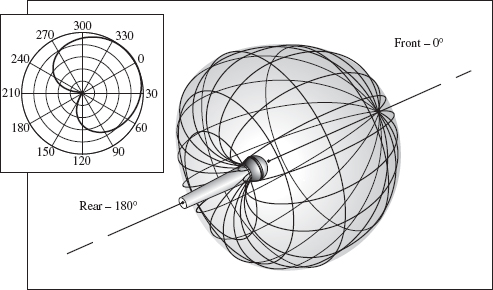
FIGURE 3.7
Cardioid pattern
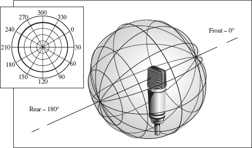
FIGURE 3.8
Omnidirectional pattern
Additional, more directional, patterns include super-cardioid (Figure 3.10 (a)) and hyper-cardioid (Figure 3.10 (b)) patterns.
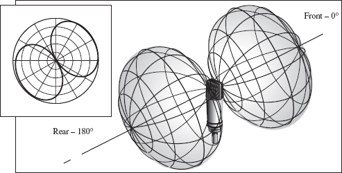
FIGURE 3.9
Figure-8/bipolar pattern
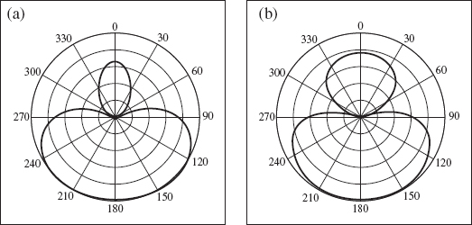
FIGURE 3.10
(a) Super-cardioid and (b) hyper-cardioid patterns
Microphone Choice
• Match the microphone to the situation. Match the characteristics of the microphone with the characteristics of the instrument, to complement its sound. If, for example, a microphone has a natural low-end boost, maybe use it on a small acoustic guitar that needs a low-end boost rather than on a bass amplifier, which may have enough low frequencies. Questions to ask before choosing the microphones might include:
- Is a microphone even necessary? Some instruments have a direct output that can be used instead of a microphone. This means no leakage from other instruments. Sometimes, for example in a live situation, the best microphone choice is no microphone at all.
- How much air is being pushed? Does the situation call for a dynamic, a condenser, a ribbon, or another kind of microphone?
- What is the dynamic range of the musical instrument? A piano has a wide frequency range; a triangle doesn't. Instruments with narrow frequency ranges may not need the best microphone in the house.
- Will an older tube microphone work better than a new one?
- Should a small or large diaphragm microphone be used? Different microphones naturally produce different responses – the ears are the final judges. Commonly, lower-frequency instruments benefit from large diaphragm microphones due to the larger diaphragm mass, which improves low-frequency response.
- How loud is the microphone? A microphone with a high output might not be the best choice for a really loud instrument, just like a low-sensitivity microphone might not be the best choice for a low-output instrument.
- What is the best placement for optimum response? Does the situation call for direct signal, close miking, or not so close miking?
- What microphone polar patterns are available and which is best for this situation?
- How many microphones are needed? Will one be enough or are two (or more) needed? Should stereo miking be used?
- Is a pad or roll-off necessary? After the levels have been lowered, is signal still too loud?
- Should I have the chicken or the fish for lunch?
Microphone Placement
• Treat microphones with the utmost care. Carry them one at a time and don't place them on the floor. Bring them in and set them up. If you must put them down, use a blanket or towel. Older tube microphones are expensive to fix and repair can take months.
• Try all the microphones available. Don't forget about that one humble microphone that sits in the corner of your arsenal for years and never gets used. I wonder how a shotgun microphone aimed at a guitar amplifier would sound, or a boundary microphone taped to the floor under a guitar amplifier, or a lavalier clipped to the hole of an acoustic guitar?
• Check please. Double check, then triple check that the microphone is attached to the stand correctly, is not touching any other stands or instruments, and is solidly in place.
• Mute the microphone before plugging in the cable. At this point of your setup, the proper cable should lie at the base of the microphone stand. Check with the control room that the channel is turned off. This avoids a great loud pop in the speakers and, even worse, through all the headphones.
• Switch off the phantom power. If the microphone has its own power supply, as many tube microphones do, turn off the phantom power at the console. In addition, switch it off for dynamic and unbalanced microphones.
• Three-to-one rule. There is an old rule for when placing two or more microphones on a single source. Place the second microphone at least three times the distance between the first microphone and the sound source. At this distance, the second microphone picks up enough of the room ambiance to minimize any phase interference between the two microphones. Figure 3.11 shows microphones that are (a) one foot from the acoustic guitar source and (b) beyond the three-foot perimeter.
This rule can be broken when two microphones are placed so close together that they are in phase, for example two microphones taped together and aimed at a snare drum.
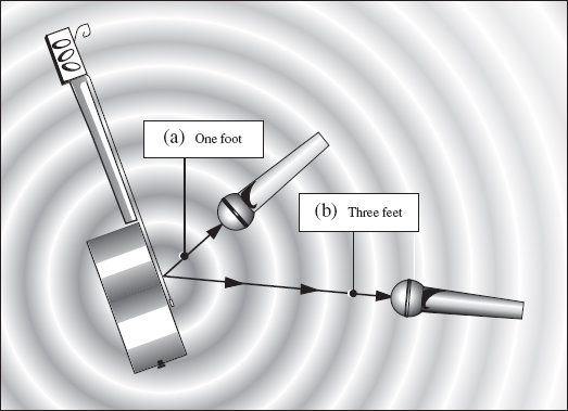
FIGURE 3.11
Three-to-one rule
• Four-to-one rule. The distance between the close and distant microphones is far more critical if the close microphone is very near the sound source. When miking an acoustic guitar with the close microphone, for example, three inches from the fret board, the distant microphone placement should be at least four times that distance. When close miking in a somewhat dead acoustic space, the four-to-one rule should be applied. In a more traditional open miking situation, the three-to-one rule is adequate.
• Port noise complaint. Blocking the ports of a microphone will change the polar pattern. Placing a microphone too close to the floor, wall, window, or any other reflective surface may cause unwanted reflections to bounce back into the microphone. Tighten the microphone's polar pattern using damping, such as a carpet on the surface, to reduce these close reflections.
• Set up a talkback microphone. A talkback microphone is a microphone placed in the middle of the recording room so that the players can communicate with the people in the control room. Set up an omnidirectional patterned talkback microphone early in the setup, as proper communication between studio and control room shortens setup time.
Close miking
• Just as it sounds. Close miking means placing the microphone within inches of the source. Some advantages of close miking might include:
- A fuller, tighter sound.
- Minimal leakage from other instruments.
- No unwanted ambiance on a track. If needed, ambiance can be added to a dry track but, once recorded, ambiance cannot be removed.
- It is easier to return to the same sound if ambiance is different, for example when using a different studio.
- More separation when recording in stereo.
• Hot stuff. A microphone placed too close to a source might compromise warmth. The hottest part of the match is not right at the head – it is further away in the flame. The strongest part of a waterfall is not at the crest, but further down, where it has had time to build power.
• Fine placement. You can really hear differences in the sound as you move the close microphone around in front of the source. As the microphone moves away from the source, slight changes in microphone placement aren't as apparent.
Distant miking
• Go the distance. Distant miking means the microphone is placed a few feet or more from the source. Advantages of distant miking include:
- A more ambient sound with greater influence from the surrounding environment. Ambiance can help establish a sense of depth. Take note: ambiance microphones, also called room microphones, can reveal flaws in the room design.
- Microphones are not in the way of players, who need to be totally comfortable.
- A second distant microphone recorded on a separate track can add placement flexibility when mixing.
- The ability to pick up a large group of musicians. (Have you ever tried to pick up a large group of musicians?) When distant miking a group of players, usually for classical music, the tonal balance captured can be better than recording with separate close microphones. The players can mix themselves better than the engineer.
- Less dynamics, often associated with, for example, vocals. With close miking, a compressor is almost a necessity, unless the singer is really good and knows how to control the dynamics of his voice. A foot or more distance between singer and microphone causes less change in level. The further away the singer is from the microphone, the more the surrounding environment gets recorded with the vocals. This is when studio design comes into play.
X/Y stereo miking
• X marks the spot. To produce a full stereo sound, place matching microphones (often microphones with concurrent serial numbers are very close in sound) in an ‘X’ position with their capsules close together (Figure 3.12). This setup essentially eliminates any phase problems between the two microphones. Use X/Y miking in restricted spaces where microphones need to be somewhat close together yet produce a good stereo image, such as over a piano or above a violin section.
The angle of the microphones will determine the stereo spread. The wider the angle, the more stereo spread, until the angle becomes too wide, creating a hole in the middle. The narrower the angle, the less of a hole, creating more of a mono signal.
Set up the two microphones so they are at the same height and have the same directional polar pattern with matching pads and roll-offs.

FIGURE 3.12
X/Y microphone setup

FIGURE 3.13
Spaced pairs
‘Spaced pair’ stereo miking
• Get spaced. A standard spaced pair technique places the microphones far apart within the recording room. The darker areas on Figure 3.13 show the common pickup areas. Setups might include:
(a) Quite a few yards apart. These room microphones pick up an ambient stereo room sound.
(b) Two to three feet apart. The wider the spacing, the wider the stereo spread. This setup gives a good stereo image without too much ambiance.
(c) Parallel, in front of an instrument. Placing both microphones parallel and aimed toward the source gives a wide stereo image. For an even wider image, place a baffle between the microphones.
M/S stereo miking
• Mono stereo? M/S stands for mid-side. This method ‘sums and differences’ the polar patterns of two microphones. Use M/S when you need to decide later how wide the stereo image should be (Figure 3.14). To monitor and control the depth of the stereo image, three channels are needed on the console.
(1) Set up two microphones, one with a cardioid pattern ‘M’ the other with a figure-8 pattern ‘S’
(2) Aim the M microphone toward the source. Position the S microphone on the same plane, but at a 90 degree angle.
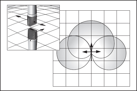
FIGURE 3.14
M/S (mid-side) pattern
(3) Route the M microphone to record on track one and route the S microphone to record on track two. The M microphone returns from the multitrack recorder into channel one and the S microphone returns into channel two.
(4) Route the S signal out of channel two into channel three so it returns on both two and three. Switch channel three out-of-phase.
(5) Pan channel one to the center, then pan two and three hard L/R.
(6) Raise channel one to set the appropriate mono level, then raise channels two and three to control the stereo width.
Decca tree stereo miking
• Decca records. The decca tree setup, used for larger situations, uses a three-microphone array (Figure 3.15). All three are set in an omnidirectional pattern, then placed left, center, and right a few feet behind and about 10 feet above the conductor. Decca tree recording is becoming more popular in LCR (left, center, right) stereo and 5.1 surround DVD recordings.
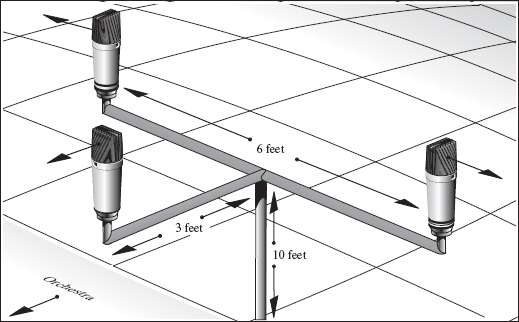
FIGURE 3.15
Decca tree miking
Decca tree stereo miking records not only on the left/right location of instruments but the fore-and background location – crucial for orchestral sessions where depth and dimension would be lost with close miking.
Direct Box
• The direct method. A direct box, or ‘DI box,’ changes an electric instrument's high-impedance unbalanced output signal to a low-impedance balanced signal that will properly interface with the microphone pre-amp. Some direct boxes are designed with an input pad and a ground switch on them. Like microphones and amplifiers, they vary widely in sound. Direct boxes are available as passive (transformer only) or active (pre-amp and transformer), where amplification raises the level to improve signal-to-noise ratio. Passive direct boxes might sound more natural than active ones due to the lack of additional processing, but active boxes may have a better frequency response.
The advantages of using a direct box include the absence of leakage, no amplifier distortion, and a full, clean sound. A good direct box records the full spectrum of the instrument where a microphone in front of an amplifier may not. Many engineers agree that a direct box alone just can't recreate that chest-cavity-vibrating thump that an amplifier and microphone can deliver.
Ground
• Ground hum. Ground loop and the resulting hum occur when electrical equipment is grounded to more than one location, creating multiple paths. In addition, hum can originate from fluorescent lights, video monitors, dimmer switches, refrigerators, and more.
• Eliminate the hum. If your audio equipment setup is humming:
- Use a dedicated AC power circuit for the studio. Some studios have outlets strictly for audio equipment, often indicated by orange wall outlets. Sometimes all the audio equipment is plugged into a large 12-outlet box, with everything on the same circuit. The outlets in the rest of the studio would be on a separate circuit and used for the coffee machine, video games, and vibrating bed.
- Don't plug a power strip into another power strip.
- Eliminate all fluorescent lights in the vicinity.
- Don't use a ground lifter – a converter that changes a three-prong plug to a two-prong plug. This can be dangerous. The third pin is there to keep you safe. Most equipment today is fitted with three-prong outlets, the third being a chassis ground just to avoid any bothersome recording engineer electrocution issues.
- Use a transformer, or hum remover, made specifically to eliminate hum by removing any common ground between devices.
- Use the highest quality, shortest cables.
- Rearrange the way the outboard equipment is stacked. A transformer in one unit may cause hum in an adjacent unit.
- Use a filter. Although the method is not recommended, a 60 Hz hum can be removed using a filter set at 60 and 120 Hz. However, this pulls that frequency on any musical content and can affect harmonics.
- Switch the direct box ground. Some direct boxes have a ground switch that disconnects the input cable shield from the output cable shield, eliminating ground loops and the resulting hum.
- When the hum is from a guitar amplifier, plug the amplifier into a different wall outlet on a different circuit.
- Have the player rotate. Single-coil pickups in guitars are notorious for humming when the player is aimed in a certain direction. The hum disappears when he points in another direction. When you find the quietest angle for the player to stand, run a section of sticky tape across the floor so the player knows just what the angle should be.
- If you still can't find the hum, use the process of elimination: shut everything off and start at the beginning turning everything on again. When the hum starts, you've found the culprit.
Phase
• Phase issues. When identical signals combine, for example when two microphones are bussed to one track, phase shift can be introduced when one of the signals is delayed. This shift or delay is measured in degrees. Figure 3.16 (a) shows that, when similar sine waves combine with no delays, the signal doubles. Figure 3.16 (b) shows that, when one signal is delayed exactly half the length of the sound wave, its polarity is 180° out-of-phase with the other signal. When combined, these signals will cancel each other out. Note that phase or phase shift involves delay. Polarity does not. Polarity refers to the + or – direction of an electrical signal.
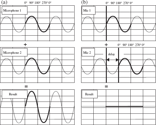
FIGURE 3.16
Phase cancellation
• Check for polarity. Somewhere along the line between microphone and monitor, the polarity may be reversed. Perhaps it's a miswired connector or input jack; maybe even a wrong button pressed. To check for polarity:
(1) Place matching microphones right next to each other, with the capsules as close as possible, both aimed toward a source.
(2) Have someone stand a few feet away and speak.
(3) Solo the two channels and listen in mono.
(4) Press the phase button (sometimes mislabeled as polarity) on one of the microphone channels. If the signal cancels, the microphones have the same polarity. If the signal cancels when no buttons are pressed, the two microphones are wired in opposite polarity (the wiring to pins two and three is reversed in one microphone's XLR connector).
• Phase – the facts. Every foot that you move a microphone away from the source results in about a one-millisecond delay. If a second microphone is placed incorrectly, the signal reaches it at a different time in the cycle.
At specific distances, certain frequencies will be out-of-phase, resulting in a thin, incomplete sound. This phenomenon occurs when recording any sound with two inputs, for example when combining a direct box and a distant microphone.
Figure 3.17 shows how to minimize phase cancellation between microphones. Figure 3.17 (a) shows two microphones placed as the session dictates. Solo the two channels, match the levels, and listen in mono. At the console, temporarily switch the polarity on the channel with the farthest microphone from the sound source.
Have the player play, preferably a single note, while an assistant moves the distant microphone (Figure 3.17 (b)), stand and all, forward and back again. When the combined sound source almost disappears, the two signals are out-of-phase, canceling each other out.
Place the distant microphone in that spot. Switch the phase button on the console back again. Figure 3.17 (c) shows that the farthest microphone is back in phase with the close microphone.

FIGURE 3.17
Minimizing phase cancellation