

CHAPTER 8
Control Room Setup
In the studio room, opening wall panels, moving baffles, laying out carpets, and hanging blankets are common methods of altering the acoustic space for your specific needs. In the control room, the opposite is applied. The room response is set and predicted. In a properly treated room, the reflections are minimized so sound reaching the engineer is not colored by the influence of the room characteristics. The environment remains consistent to accurately monitor what is being recorded and replayed.
Control Room Analysis
• What is a spectrum analyzer? A spectrum analyzer shows an accurate readout of a room's frequency response. To analyze a control room, a technician with a trained ear places a microphone about where the engineer's ears will be, then plays pink noise through the speakers at various volume levels. The spectrum analyzer displays a readout of the room's frequency response as modified by the reflections.
The technician might insert a graphic equalizer between the amplifier and the speakers to ‘flatten’ the room. He might pull a resonant frequency of the control room in order to decrease any unwanted influence.
Not unlike using an electronic tuner to tune a musical instrument, the spectrum analyzer is just an aid. Ultimately, the technician's trained ear will determine what sounds correct.
• Place all equipment in its final positions before tuning the room. Once the room is tuned, moving machines and racks of outboard around may change that tuning.
• Listen man. Beginners may not be sure of what sounds ‘right,’ so, when the technician is tuning your room, have him explain what he is doing. Listen to and note what frequencies are boosted or pulled, and why.
• Understand the room's limitations. If you can't physically change the control room or the speaker equalization, at least understand the deficiencies so you can aurally compensate. For example, if you know the room has an inadequate low-end response, you might want to push the low frequencies a little more than you normally would. This takes well-trained ears, and usually comes only with years of experience.
• What is a bass trap? A bass trap is a dissipative device placed or built at the back, sides, or corners of a room to absorb a room's resonant frequencies and therefore its harmonic intervals. Something as simple as another room behind the control room would be considered a bass trap. Once a control room has its resonant frequencies controlled, and has the correct mid-and high-frequency absorption to get uniform reverb time versus frequency, it is referred to as a neutral room.
Control Room Preparation
• Keep the room clean, organized, and stocked. A clean work environment shows that you are serious about your job. A messy space makes people more anxious and, if the place is a total wreck, clients think your tracks are the same way. No matter how much or how little clients are paying, they expect quality.
Stock the room with colored felt pens, duct tape, energy bars, band aids, earplugs, aspirins, vitamins, guitar strings, a drum key, pencils, pens, tracksheets, recording maps, batteries, labels, console tape, speaker fuses (especially when recording loud drums), and all the peripheral items needed to keep the session going. Place all computer documents in the same file and keep everything well labeled.
• Get the lead out. Place a notepad and a couple of sharpened pencils on the console. While recording, jot down the counter number on any mistakes or questionable bits and check them when appropriate.
• Put an air purifier in the control room. A clean-smelling control room is so much nicer to work in. Portable air purifiers can change a room from rank and dank to clean and pristine.
• Who's on first? Mute the console and headphone amplifiers before powering up or down. Power surges can blow fuses, speakers, and headphones. Power amplifiers are the last things turned on before the session and the first things turned off at the end of the day.
• Equipment placement. Place outboard gear, especially equalizers, where you can adjust them while you are within the stereo spectrum. If they are across the room, you won't be able to hear the changes as you make them.
Equipment needs plenty of ventilation so everything stays nice and cool.
• Confirm equipment rental arrangements. If you sign for the rental, check the equipment for any dents, scratches, or flaws, and note the serial number. Like renting a car, if it comes back with a dent, you are responsible.
• Check your gear. Use an oscillator to verify that all recorder and processor inputs and outputs are correctly connected to the console. Listen to check whether all the processing equipment is indeed coming through as it is supposed to, with no loading, incorrect patches, or unwanted processing at the console. If something is not working, you want to know before the session begins.
• Open says me. Turn on the computers and applicable hard drives, and open the proper programs. Check that all inputs and outputs are correct and the system is ready to record.
Digital Recording
Due to low-cost and high-quality results, all studios today have some kind of digital processing. The function of digital recording is the same as analog. Record in real time, then edit, then mix. Our only limitations are the amount of free space on our hard drive and the number of simultaneous inputs/outputs that our audio interface or recording software is able to deliver.
• Place the DAW screen between the front monitor speakers. In some studios, the computer workstation has its own set of monitors. In others, the output signal is routed to the main studio monitors. Place the computer monitor screen so you can see it while facing the monitor speakers.
• Use the highest quality sound card available. The less expensive cards use cheap A to D converters that introduce a ‘grainy’ quality to your sounds.
• Turn that thing off. Shut off the power before moving the hard drive. The internal discs are always spinning, so moving the drive might corrupt data.
• Set parameters with the project in mind. Before recording to hard drive, establish the parameters of use, such as bit depth, sample rate, and reference level. The session setup windows must be addressed when a new session is started. Some of these cannot be changed later. If previous files exist, maybe match your new settings with those settings so all files are the same.
• Few standards. The analog world has well-established standards but the digital world has few. There are many horror stories of files from one DAW not working on another DAW due to incompatibility.
Use the following guidelines to make sure you have a smooth-running session. It helps if you know what the final output medium will be. What is the recommended:
Sample rate? For CDs, 44.1 kHz is the required sampling rate, so recording at 44.1 kHz avoids signal degradation when downsampling. For all other media, use 48, 88.2, 96, or 192 kHz.
Bit depth? 16-bit or 24-bit. All modern playback systems can handle 24-bit. With the low cost of modern hard drives, the small amount of space saved using 16-bit might not be justified. The only time to select 16-bit might be audio mastering for the final CD. But many projects might not ever see a CD. They may go directly to a film or movie soundtrack, they may go to a computer format, or maybe to an as-yet undetermined storage device.
Reference level? In video and film, –20 dBFS peak level corresponds to 0 VU average, or RMS level. In digital audio there are no standards. The most common ones are –16 or –18 dBFS for the multitrack part of the project. When mixing down to stereo or surround audio, –12 or – 14 dBFS = 0 VU.
• What is a clocking reference? Almost all professional digital equipment uses a master clock either derived from the internal clock or synchronized to a central, or external, clock. Some cheaper digital processing equipment may lack a high-quality, stable internal clock that generates the sample rate. Using a higher-quality external clock will vastly improve the sound of the converters and plug-ins of your digital processor.
• What are plug-ins? Digital plug-ins are small apps that process the digital sound file. They represent outboard effects that in an analog world would be part of the studio's outboard rack. Equalizers, compressors, gates, reverbs, and delays are ‘plugged in’ after you have recorded the sounds flat to your hard drive. In the analog world this would be like recording all your sounds flat to the multitrack recorder then processing the sounds on the monitor panel part of the console.
• Plug-ins will create a slight delay in the sound file. Every plug-in has a different processor delay (normally stated in samples) called latency. This delay can range from a few samples to many thousands of samples, depending on how complex the effect is. This timing error can become noticeable if you add many plug-ins to, for example, the snare, and nothing to the kick. What was a tight drum track is now skewed somehow. In this example, maybe copy the snare track then nudge the copy forward so the resulting track matches the timing of the rest of the drums. Some DAW software corrects plug-in latency. As ever, check the phase between tracks.
• I've created a master. Create a master template file with everything properly labeled, bussed, and assigned. Start a new session at a moment's notice with everything set up just as you like it.
Speakers
• What is a loudspeaker? A loudspeaker is a transducer that changes electric current to acoustic signal. Not unlike a dynamic microphone, a diaphragm houses a voice coil that hovers within a magnetic field. The voice coil reacts to the applied current, causing the diaphragm to recreate the equivalent waveforms.
• What is a studio monitor? A studio monitor is, at least in most studios, more than one speaker. Because one speaker cannot reproduce the complete audible frequency range, different speakers cover different ranges. Often larger recording studios will have large mounted speaker arrays aimed at the engineer, as well as various nearfield monitors. Figure 8.1 shows a common three-speaker studio monitor with two amplifiers. This includes:
(a) Crossovers. A crossover is the network of pass band filters that splits the signal feeding the individual speakers, sending only the high frequencies to the tweeter and the low frequencies to the woofer. Some crossovers are active, or amplified, to allow the user to set the individual speaker level, the frequency of the transition, and the slope of the crossover. Larger mounted studio monitors may have more than two speakers, each with its own amplification.

FIGURE 8.1
A studio monitor
(b) Amplifiers. In this example, the first amplifier's left side powers the tweeter and the amplifier's right side powers the woofer. When a second amplifier is used for the subwoofer, the stereo output is commonly bridged for a louder mono signal.
(c) Tweeter. A small speaker used for high frequencies. The crossover pulls all low and mid frequencies before reaching the tweeter. Larger mounted speakers sometimes use a ‘horn’ for a tweeter.
(d) Woofer. A larger speaker used for low to mid frequencies. Frequencies beyond this speaker's rated range are rolled off.
(e) Subwoofer. A large, heavy-duty speaker designed specifically for the very lowest frequencies.
• What is a nearfield monitor? Nearfield monitors are placed a few feet in front of the engineer, often on stands just above and behind the meter bridge. Whereas room shape and treatment heavily influence the sound from big mounted studio monitors, nearfield monitoring is influenced far less by the surrounding environment. Still, all front areas of the room should be designed to push sound to the engineer's ears with as little interference as possible.
• Position of power. Figure 8.2 (a) shows the nearfield studio monitors and the listener's ears in a triangle. With the monitors equidistant from the listener's ears, the mix of left and right arrives at both ears simultaneously. Figure 8.2 (b) shows that monitor speakers on stands produce less console reflections. Placing woofers at ear level is less crucial as the low frequencies are less directional.
• Clear your speakers of debris. Any items placed on top of your nearfield monitors will eventually vibrate off, landing on the console.
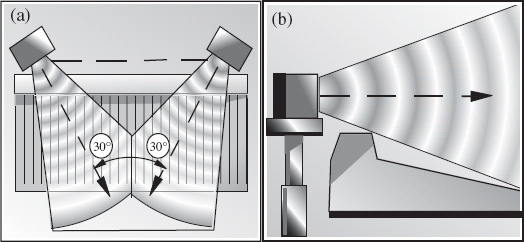
FIGURE 8.2
Nearfield monitor placement
• Place speakers out of corners and away from walls. Close proximity reflections can cause interference with direct signal, creating phantom images. If it is not possible to move the speakers, deaden the corners to reduce unwanted reflections.
• Rainbows everywhere. Place your speakers away from video monitors. The magnets, if unshielded, mess with the colors on the screen.
• High-ratio hornblower. Use the best speaker cables available and add in-line fuses to your speakers – always install the recommended fuse. High peak levels, for example when the drummer hits the kick, will translate into high current and can overload the speaker. Hopefully the fuse will blow before the speaker, saving the speaker. Replacing a fuse is cheaper.
• Use a powerful monitor amplifier. Low-powered amplifiers will overload sooner, creating unwanted distortion. The speakers should distort well before the amplifiers distort. Many engineers today use nearfield monitors with built-in amplifiers.
• Add a subwoofer sparingly. The home listener may not have a subwoofer. If you are using one with your small speakers, move it around to find the best placement and occasionally check the sounds without it. If the low frequencies in the studio are enhanced with a subwoofer, the sounds might be bass-shy when played somewhere else.
Without a properly connected subwoofer, small speakers can blow because the low end is too powerful.
• Play with your bottom. Once the nearfield monitors and subwoofers are correctly placed, set the equalization (located on the back panel of the speaker) flat and listen to a favorite disc. Many professional nearfield monitors allow the user to change the speaker equalization and crossover frequency. Try different speaker models for an overall feeling of how the room sounds.
When we know that the room and speakers are properly equalized, we can rely on our ears knowing that what we hear is a correct representation of what is being recorded. The room should be designed and tuned so all frequencies are kept under control – no major frequency bumps or dips should exist, all outside noises should stay out, and all inside noises should stay in.
Console
• Understand the console. Of course, the console is the routing station where all incoming signals are sent on their merry way to wherever you choose, for example to the multitrack recorder, the monitors, or the auxiliary cue sends. The console enables you to use equalization, panning, effects, and dynamic range as building blocks for the best possible sound.
And remember the terminology: the console has channels and the multitrack recorder has tracks. Commonly, the signal is called the track.
Whether it is a 12-channel console, a 48-channel console, or a DAW, the principle is the same. The channels process incoming signals such as microphones, direct signals from instruments, returns from the multitrack recorder, and returns from effects. Signals are then assigned a location and finally mixed to a master output, often stereo. Without a total understanding of the console flow, the engineer cannot use it to its maximum potential.
• What are VU and peak meters? VU, or volume unit, meters average the signal level much like the human ear does. VU meter readings correspond with perceived volume. Peak meters show the peaks, or the maximum signal, of transients that do not register on the VU meters. The peak meter readings accurately show the recording levels.
• Label the console. Use the scribble strip to clearly label the channels on the console with all relevant information including microphone and line inputs, multitrack returns, cue sends, and effects. Lay a strip of white adhesive tape across the length of the console, as tape tends not to smudge. A separate strip of tape for each song can be pulled off the console and taped to the wall for future use, saving time when changing from one song to the next.
• Getting loaded down at the bay. Clear the patch bay of all patches. Improperly grounded external equipment can cause hum. Partly plugged-in patch cords could cause channels to ‘short’ out or crackle.
• Mute the channel. Mute the channel before making a patch. Dirty patch cords can cause grounding buzz, click, or crackles as the patch is made.
• Check the microphones. Once the console is set and the inputs are properly routed, have a runner scratch the head of each microphone to check that each one is properly connected. Or have him snap his fingers in front of the microphone. Some engineers prefer finger snaps, especially jazz engineers.
• Check the headphones. Go out to the studio room and listen to all the headphones to make sure the cue sends are connected and checked for each individual player. Each player's headphone set should have ample signal level, with everyone hearing the talkback microphone.
Equalizers
Better recording studios have racks of outboard signal processors including equalizers, compressors, limiters, and effects. Equalizers process frequencies by raising and lowering the amplitudes of chosen frequencies within the audio spectrum. Different instruments and voices exhibit different frequency characteristics. Compressors, limiters, and noise gates process dynamics. Effects such as delays, reverbs, and choruses process time. See Chapter 11 for more on effects.
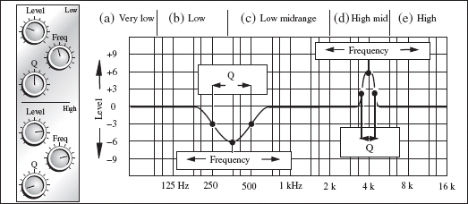
• The trouble with trebles. Learning how to equalize is a lifelong pursuit for the recording engineer. The more you listen, the more you realize that every sound has a complex waveform structure, and each sound interacts differently with other sounds. Although we cannot hear the very high and low frequencies, they still interact with the frequencies we can hear and contribute to the overall sound. Figure 8.3 shows the equalization frequency response broken down into:
(a) Very low. 80 Hz and lower contains rumble and mud. Low E on a regular guitar is 82 Hz. Low E on a bass guitar is 82 Hz. Below that is only rumble from trucks or air conditioning.
(b) Low. 80–350 Hz contains an instrument's trunk and body. Boosting in this area brings out natural fundamental tones.
(c) Low midrange. 350 Hz–2 kHz contains the body and meat of a sound. Most instruments have substantial harmonics here.
(d) High midrange. 2–6 kHz contains placement and definition. High-mid frequencies can bring presence to a track and can bring it to the forefront. When pulled, they can cause the track to blend into the background.
The equalizer
(e) High. 6 kHz and higher contains crispness, clarity, and presence. The higher frequencies, from 12 kHz on up, are known as ‘air’ for their brilliance and high sheen. Overuse can cause symptoms not unlike an icepick to the forehead.
• What is Q? Q, for quality, defines the width of the bell curve that is affected when boosting or cutting equalization. The bell curve, so named because it is shaped like a bell, contains the frequencies slightly above and below the center frequency. These adjacent frequencies are affected as signal level is raised and lowered. Today's computer plug-ins allow the user to change the bell curve to much steeper values than traditional analog designs.
• Q the music. The Q value equals the center frequency (in Hz) divided by the bandwidth (in Hz). Bandwidth is measured at –3 dB of the peak of the chosen center frequency. When cutting, bandwidth is measured at –3 dB below the horizontal axis, resulting in a thinner Q value.
Figure 8.4 shows a wide Q setting (two octaves), a medium Q (one octave), and a medium thin Q (half an octave).

Q curves
Equalizing
• Don't twiddle. Ask yourself ‘is equalization necessary?’ Go into the studio and listen to the actual instrument or sound source. As the player plays, listen to what frequencies are apparent in the studio but missing in the control room speakers. The ideal situation is to get the right sound at the source, then record it with as little processing as possible – not always easy to do. Before reaching for the equalizer, maybe:
- Move the microphone. Higher frequencies are directional and sometimes a small placement change can make a world of difference.
- Change parameters on the microphone. Maybe a pad or roll-off could be installed or removed.
- Change the microphone. All the equalization in the world cannot replace using the right microphone.
- Ask the player to adjust his instrument or amplifier tone, or maybe even his playing style.
- Replace the strings or drum heads, if applicable.
- Add, remove, or change compression.
- Try something as simple as changing the pan placement.
- Replace the player. Better players sound better, so they are easier to record. A recording is forever, so bringing in a professional session player is not uncommon.
• Match and set. Match the equalizer with the situation. A good equalizer is rich and musical, yet razor sharp at honing in on certain frequencies. As with microphones, different brands and types of equalizer can be used for different instruments and situations. For example, if the equalizer is being used to simply roll off some low frequencies, you might not need a full bandwidth equalizer.
• Smear campaign. Adding equalization also adds phase shift, a degradation in the waveform that increases with added processing. This ‘smearing’ can cause a track, especially a vocal, to lose clarity in the final mix. Plus, adding high end boosts the hiss and inherent noise that come from the microphone, the console, the outboard equipment, and all else along the audio chain.
• If you must equalize, keep it musical. Use the musical content of the instrument to determine where to add and pull frequencies. Each musical note's complex waveform is made up of its fundamental tone, plus that tone's harmonics and overtones. The richness of a sound lies within these overtones and other harmonic frequencies, so adding and pulling random frequencies just adds non-musical clutter. If, for example, the song is in the key of A, there will be a lot of buildup around 220 Hz and its harmonics (440 Hz, 880 Hz, etc.). Logically, these harmonics are where the meat of the sound resides. Figure 8.5 will help you find specific musical tones and overtones.
• Pull before adding. Pulling a midrange frequency then raising the overall level often works better than adding highs and lows. The response is smoother with less risk of overload.

FIGURE 8.5
Frequencies to tones
• Freq. out. Minimize frequency overlap by pulling offending frequencies that mask more important sounds. Pulling a frequency on one track changes the way other tracks interact at those frequencies. Figure 8.6 shows the frequency response of equalization applied to two guitars.
On guitar (a), around 250 Hz is being pulled with a bump around 4 kHz to give the guitar some presence. On guitar (b), around 250 Hz is brought up and somewhere around 4 kHz is pulled to let the other track shine through. When all frequencies are accounted for, with no overlap, the result is a tonally balanced sound with both definition and clarity.
• Q tips. Proper Q settings can play a key roll in creating distinction between instruments. Set too wide, it affects frequencies that might not need affecting. Set too thin, it may not get the job done.
• Thin Q very much. As you sweep to locate certain emphasized frequency ranges, use the meters to determine where the peaks begin and end. Set your Q according to these points. Note that the meters are only an indication and should not be used as the final determination.
• I boosted it, then I cut. To locate specific frequencies, the tried and true still stands the test of time.
(1) Lower the track level.
(2) Pan the track up the middle to center it between the monitor speakers.
(3) Have the player play the part. Listen for the general frequency range you wish to address.
(4) Turn up the level of the equalization, adjust the Q, and sweep the equalization until you determine which frequency range needs to be addressed, whether it's muddiness being pulled or crunch being added.
(5) Find the right spot, then return the level and the Q to a less drastic position. A wider Q pattern can result in a less ‘pointy’ sound.
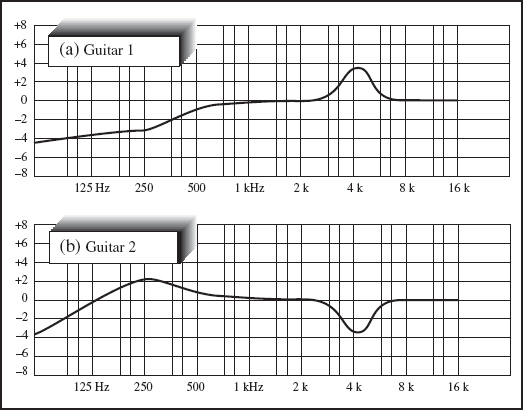
FIGURE 8.6
Minimizing frequency overlap
• Use a wide Q when adding equalization so less level is needed. When pulling equalization, keep the Q setting narrow so the richness isn't lost by cutting too wide a swath. This may help to preserve the tone a little, rather than make the instrument sound lacking.
• No peaking. Excessively high equalization levels, such as plus or minus 8 or 10 dB or more, rarely sound good, and high peaks are a nightmare for the mastering engineer.
• Too much equalization can overload. Because equalizer filters are active circuits, adding level to one frequency adds level to the overall signal. Channels easily overload when there is an abundance of equalization.
• Find and pull the instrument's resonant frequency. Some instruments, such as the bass guitar, can have pronounced boom at certain frequencies. Sweep the general areas where you feel these resonant frequencies lie and, if necessary, pull them a bit.
• Enhance a frequency. Boost (or cut) at double (or half) a certain frequency, making the desired change a bit smoother. For example, if you are boosting at 220 Hz, add a bit of 440 Hz and pull off the 110 Hz a bit.
• Zero must tell. Find a specific frequency to change by pulling out all the low frequencies. This will help zero in on the midrange frequencies. Once set, bring back the low end.
• Watch your bottom. On budget consoles, the equalization settings may not be sweepable, but fixed. If the kick drum, the snare drum, the tomtoms, the bass, the guitars, and the vocals are all boosted at 100 Hz, they will meld together as one indistinct murky blob. Better to use microphone choice and placement to get your low frequencies just right.
• Overequalize. There are times when drastic equalization is needed. The trick is to know when and how much. When a feature instrument is not as large as it should be, maybe that's the time to lay it on thick. Maybe.
• Don't overequalize. Think of the painter who wants his painting to be very bright so he mixes the brightest greens with the brightest reds, yellows, and blues. Individually, they are all very bright. Combined, they turn into a mass of dull brown and gray.
Each instrument must be laid out on the canvas so all colors can be seen and the whole canvas is used – even if some spaces are left white.
Compressors
• What does a compressor do? A compressor reduces the dynamic range of an audio signal. Most musical instruments and vocals are so dynamic that a compressor is needed to raise the lowest levels and lower the highest levels. Like an automatic level control, this process raises the apparent loudness of the signal, bringing out the quiet notes that may otherwise be lost. But raising low levels also raises the noise floor. The challenge is recording the hottest signal level with the lowest noise possible. Compressor controls can include:
Input/output. Most compressors have, at the very least, a level control. Raise the input too much and you will overload the input circuits. With not enough level, noise is introduced when the compressor output signal is raised.
Threshold. The threshold determines at what point the compression begins to take effect. Any incoming signal that exceeds the threshold gets compressed. A higher threshold means less of the signal is affected. Figure 8.7 (a) shows a high threshold where minimal signal is affected. Figure 8.7 (b) shows a medium threshold, and Figure 8.7 (c) shows a low threshold, where most of the signal is affected.
Ratio. The ratio is the dB change in the compressor's input signal compared to the dB change in the compressor's output signal. The envelope in Figure 8.8 (a) shows that a 1 : 1 ratio is unity gain, or no change from input level to output level. Figure 8.8 (b) shows a 2 : 1 ratio: for every 2 dB coming in, only 1 dB change goes out, once the threshold is reached. Figure 8.8 (c) shows an 8 : 1 ratio. When the ratio reaches 8 : 1 or 10 : 1, the compressor becomes a limiter. A high ratio combined with a low threshold results in severe changes in sound and level.
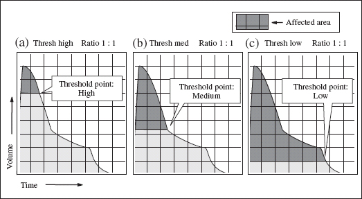
FIGURE 8.7
Threshold

FIGURE 8.8
Ratio
Attack and release. The attack and release functions define the speed of the compressor action. The attack time is the time the compressor takes to react to a strong signal. The release time is the time the compressor takes to return to unity gain after that strong signal has passed. Some instruments take a few milliseconds for the power to build, so their peak point is not instantaneous. A snare may have a faster release time and a piano may have a slower release time, due to its natural ringing out.
Figure 8.9 (a) shows that, if set too slow, the attack will allow the peak to pass before compression kicks in. If set properly, Figure 8.9 (b) shows the attack and release controlling the sound properly. Set too fast, Figure 8.9 (c), the compressor misses the peak.
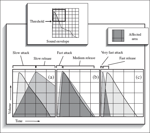
FIGURE 8.9
Attack and release
Additional Processing
As with equalizers, compressors vary in their build and application, giving the user a wide range of options, including:
Soft knee. Also called over-easy, this setting eases the compression in, avoiding an abrupt bump. This gradual transition makes the effect less noticeable.
Hard knee. The compressor has an abrupt transition from unity gain to compression at the threshold point. Hard knee preserves the attack element, or hardness, of a sound, where a soft knee would soften the transition.
Split. Some compressors have a circuit that splits the signal, processes and distorts one to enhance the harmonics, then allows the user to add this processed signal back into the signal path.
Multiband compression. Low-, mid-, and high-frequency bands can be processed individually, allowing the user to compress the low frequencies on a track differently from the high frequencies.
Gain reduction meter. The meter goes from 0 VU and down to display the gain reduction – the amount of reduction being applied to the signal at any given time.
Link. To avoid shifting images, some compressors allow the user to link it with another compressor to process a stereo signal equally in both channels.
Sidechain, or key in, or duck. Used to ‘trigger’ one channel off another. Normally a compressor reacts to its own incoming signal. Using a sidechain makes the incoming signal react to the dynamic levels of the sidechain signal. For example, radio DJs use the sidechain to automatically lower the music level when they want to talk over the music. When they talk, the voice plugged into the sidechain triggers the compressor and lowers the music to a pre-determined level. When the DJ stops talking, the signal returns to its original level.
De-esser. A compressor with a frequency-dependent sidechain. A deesser compresses only high-midrange frequencies that contain sibilance, such as ‘S’ and ‘T.’ The de-esser is used mainly on the vocal track to reduce sibilance while still retaining the crispness and high end.
• Different compressors might be:
Peak Limiter. A limiter is a compressor with ratios of 8 : 1 or 10 : 1, or higher. Used to control the very fastest and loudest of signals, it stops the signal's output from exceeding a certain level, regardless of the input level. The peak limiter works on the peaks, or initial spikes – the loudest initial part of a sound – rather than RMS (average), as other compressors do.
Leveling amplifier. This is a basic compressor with preset medium attack and medium release times and only input/output level controls, with stepped ratio control.
Vacuum tube/valve. Vintage microphones, amplifiers, and limiters may contain vacuum tubes, also called valves. These tubes distort musically and create a warmth that makes tube equipment a favorite for many engineers.
Compressing
• Choose with care. As with microphones, compressors must be chosen for each situation. The right compressor with the correct settings will improve intelligibility and placement, making the track appear louder.
• If adding equalization, place the compressor before the equalizer. This allows you to fix the equalization settings without having to compensate on the compressor. But, maybe the pre-amp in the equalizer is better than the pre-amp in the compressor. This may mean that the equalizer comes first in the chain.
• If pulling equalization, place the equalizer before the compressor. Pull unwanted frequencies such as low-mid muddiness so that the compressor reacts to the equalized sound, not the pre-equalized sound. Sometimes the equalizer can't handle the incoming peak levels, so the sound needs to be compressed first.
• Don't overcompress. Too much compression tightens up the air and can eat all the dynamics of the track and produce a lifeless sound. Some engineers love to use lots of compression as part of their sound.
• Overcompress. Let's say you have a great guitar sound but it needs more attitude for that real in-your-face feel. A low threshold and high ratio, together with proper input and output settings, will ‘squash’ the sound for a more ripping tone. Too much compression can suck all the dynamics out of a track so the output level will stay the same no matter what the input level is.
Overcompression can enhance the low frequencies, but it steps on other tracks in that frequency range. Once the compressor settings are as you want them, re-examine the equalizer settings.
• First in line gets set up first. If you have set up a compressor, then a peak limiter, then an equalizer, start with the settings on the compressor.
• Use the peak/RMS switch. If a signal has a lot of transients, such as a high hat track, set the meter for peak so you can see if any of the transients are overloading. For a track that may have less transients, perhaps a vocal, set the meter to RMS to see the average levels of the waveform.
• Set the attack according to the instrument and the music. A string pad might have a slower attack time than, say, a jarring staccato violin piece. Consider the instrument, the music, and how the music is played when setting attack time.
• Don't compress the whole signal if one frequency band needs it. Use a multiband compressor when only certain frequencies need to be compressed. This won't affect the other frequency bands that don't need compression.
• Set the release time to match the tempo of the music. A faster song would likely have a faster release time. Too long, though, and the release will still be recovering when the next signal hits.
A longer release time can smooth an instrument's decay. Too short a release time results in pumping and breathing – the sound of the release returning to unity gain too early.
• No compression, but no overload. Add another limiter to totally stop any signal from going beyond a certain point, but without ‘compressing’ the signal. Set a very high ratio such as 10 : 1 (the point of limiting) and set the threshold on the highest setting to allow everything to go through unaffected. Play the signal at its loudest and lower the threshold until you see meter movement. Go back and forth between ratio and threshold until you find the right settings for your situation.
• Peaking duck. The limiter output signal level should have the peaks just reaching – 1 dB. Set the output level so it doesn't quite reach the overload point, yet captures the maximum signal level with minimal noise. The ideal situation is to set the limiter's input level so that the dB reduction meter is not moving during the main musical parts. The compressor kicks in when a loud part of the song hits.
Noise Gates
• What is a noise gate? A noise gate, also called an expander, works in the opposite way to the compressor. Unless a certain input level is reached, the trigger will not open. As with a compressor, a noise gate includes features such as threshold, attack, and release. It may include a ‘hold’ setting, which tells the unit how long to wait before the release, and a ‘duck’ setting, which activates the sidechain. Noise gates, like compressors, are commonly placed within the chain of a signal track and not across a send, as a reverb would be. Figure 8.10 (a) shows the incoming signal, (b) the gate settings, and (c) the outgoing signal.
• Hum free. A gate will only eliminate hum when the instrument is not playing. Once the player starts, the gate opens and the signal, with the offending hum, comes through, loud and clear. Best to eliminate all the noise before pressing the record button.
• Install a reverse gate on the talkback microphone. When the players play, the volume in the studio will cause the gate to react, in effect turning off the talkback microphone. When the music stops, the gate opens and activates the talkback microphone. This allows more freedom than always having to reach over and continually turn the talkback microphone on and off.
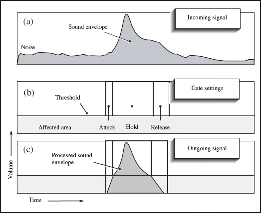
FIGURE 8.10
Noise gate
• Chop that. Create a great staccato sound on a keyboard pad by running the noise gate across the pad, then trigger the sidechain input with a tight high hat track. This results in a choppy sound effect on the pad that is always in time because it is triggered by the high hat.
• Noise note. A noise gate will not eliminate buzz. It will make the buzz seem worse because when the sound returns after being lowered, the buzz returns too.