

CHAPTER 13
Appendix: Digital

Digital recording systems store and retrieve numbers. Big numbers. These systems are broken down into three stages: input processing, storage, and output processing. Output processing is input processing in reverse, so, if you understand the input process, you get the output process.
In its simplest form, analog sound is a linear series of individual waveforms. Digital processors change the linear aspect of the analog signal to specific steps of varying voltages, not unlike a cartoon, where what appears to be continuous motion is actually a series of maybe 16 drawings per second, stored in a specific order. As each drawing takes 1/16 th of a second in time, the cartoon's sampling rate would be 16 (if cartoons had sampling rates). Similarly, each ‘sample’ is recorded as a specific voltage for a specific length of time.
Each voltage sample is read and assigned an equivalent number. With sampling rates of up to 48 000 times a second and higher, these are some pretty hefty numbers. How does the computer store and retrieve them so fast? By converting the numbers from our familiar decimal counting system to a simpler binary counting system.
Digital Conversion
Binary codes
Do you have a social security number? I have. Do you have a driver's license number? I have. Do you have a ‘Cheese of the Month club’ member number? I have. One thing can be represented in many different ways.
The eggs in Figure 13.1 are commonly represented by the decimal number 12 – 1 block of 10 with 2 left over. In an octal (8) system, these eggs are represented by the number 14 – 1 block of 8 with 4 left over. In a binary system, they are represented by the number 1100.
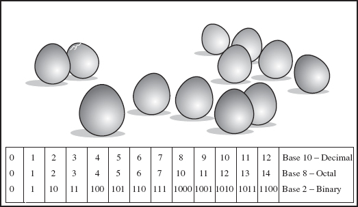
FIGURE 13.1
Different counting systems
The binary system is far easier for a computer to deal with, because the computer recognizes 0101, or 0110, far faster than 9 or 4. There is little room for error when there are only two choices: 1 or 0, on or off. The actual numbers themselves are longer, but they still represent the same amount. If human beings had been born with one arm and five fingers instead of two arms and ten fingers, we would probably count using a pentamel (5) system rather than the decimal (10) system. Plus, way more people would be named Lefty.
Bit processors
The processor stores numbers in bits (BInary digiTS). To count to 16 (0 to 15 = 16 digits) using the binary system, four bits are needed (Figure 13.2). Switch that statement around, and a 4-bit processor holds up to 16 decimal numbers. For the system to hold more numbers, or finite steps, a larger processor is needed. A 16-bit processor can hold up to 65 536 numbers, and a 24-bit processor can hold over 16 777 000 numbers. Longer bit length means more finite steps and a more accurate A to D conversion.
LSB versus MSB
The lowest digital levels – all zeros – are referred to as the LSB, or least significant bits. The highest levels – all ones – are the MSBs, or most significant bits. Low incoming levels activate the least significant bits, and hotter levels activate the most significant bits. The idea is to take advantage of the most bits possible. Lower levels mean less bits are being used, resulting in a ‘grainy’ sound plus increased noise when the level is raised.
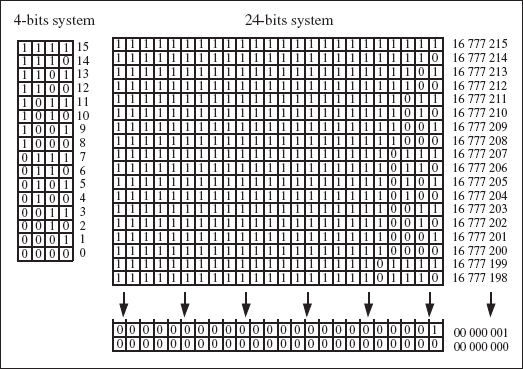
FIGURE 13.2
Low bits versus high
Input Processing
Dither
Before the signal can be converted to digital, the input signal needs to be processed. When an incoming voltage level is not strong enough to reach the lowest quantization level, digital distortion is introduced. Dither is low-level noise (white noise, square wave, or sawtooth, depending on the equipment manufacturer) added to the signal to mask this distortion by increasing the level beyond the lowest quantization threshold. This moves the incoming audio level up into more significant bits, producing a more accurate conversion of analog signal. Not unlike bias used in analog recording, this additional signal is added to improve reproduction.
Adding dither is recommended when converting a signal to a lower bit depth, for from 24-bit to 16-bit. Dithering retains some of the 24-bit quality in the 16-bit signal.
Aliasing
Aliasing refers to errant frequencies introduced into the audio spectrum. The Nyquist Theorem states that aliasing will occur when the sampling frequency is not at least two times the size of the audio frequency. So, what happens when the sampling rate is set at 48 kHz and the musical overtones reach 24 kHz and beyond?
Figure 13.3 (a) shows that, when the frequency equals or is higher than half the sampling rate, the signal is no longer accurately reproduced. Figure 13.3 (b) shows how a low-pass filter, also called an anti-aliasing filter, passes the low frequencies and stops any frequencies that may cause aliasing.
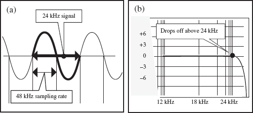
FIGURE 13.3
Anti-aliasing filter
In this case, anything under 24 kHz can pass through. To sample at a rate of 88.2 kHz, half would be 44.1 kHz; the anti-alias filter would remove all frequencies over 44.1 kHz. A sampling rate of 96 kHz would need an anti-alias filter over 48 kHz.
Sample and hold
The A to D (analog to digital) conversion is done mainly in two steps: first, sample and hold; then quantize. With a 48 kHz sampling rate, each voltage step is held for a duration of 1/48 000 of a second, assigned a corresponding binary number (word), then stored and stacked as packets of information (Figure 13.4).
Quantization/error correction
If a binary number is not available for the exact incoming voltage, the converters round out to the closest available number. Figure 13.5 (a) shows a 4-bit processor with an 11 kHz sampling rate. If an incoming voltage level is 0.46012 mV, the reader would assign it to the closest available number, maybe 0.5 mV.
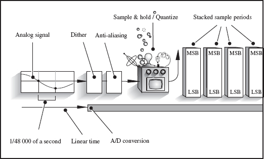
FIGURE 13.4
A to D (analog to digital) conversion
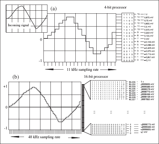
FIGURE 13.5
Quantization
Figure 13.5 (b) shows a 16-bit processor and 48 kHz sampling rate. Much less rounding out is applied, vastly lowering the quantization error. An incoming voltage of 0.46012 mV would be recorded as 0.46012 mV.
Oversampling
To preserve as much of the higher-frequency content before the antialiasing filters, oversampling widens the frequency bandwidth and allows for a smoother and extended frequency slope. Figure 13.6 shows the process that averages out the distance between two samples, adding another two samples (or four samples, or eight and so on). This doubles (or quadruples, etc.) the sample rate. This linear quantization reduces phase distortion and lowers the noise floor.
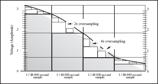
FIGURE 13.6
Oversampling
Digital Storage
Pulse code modulation
It's one thing to convert numbers to binary and yet another to physically store them for future reference. Pulse code modulation, PCM, is the actual switching mechanism between a zero and a one. The data stream switches from zeros to ones using voltage pulses that modulate between on and off. The medium records a pulse of voltage as a 1, and no pulse as a 0, all within a specific timed framework referred to as the clock rate. Like an orchestra leader, the clock keeps all operations synchronized to a common reference time.
• What is jitter? Jitter is the slight timing variations of the sampling period. Ideally, a track should be recorded and played back at a perfectly fixed clock rate, but, in the real world, minor fluctuations occur. These fluctuations can skew the waveforms on playback, causing jitter. Jitter is a function of the A/D, D/A conversion, and does not occur when the signal remains digital.
Digital Multitrack Recording
Rotating drum
DAT machines use rotating drum technology (borrowed from the video world) to achieve high-quality recordings using a relatively slow tape speed. The incoming signal is combined into a single-bit stream, then inputted to the buffer at a specific clock rate. This internal buffer then ‘time compresses’ the digital stream by using a faster output clock, resulting in time-compressed even and odd blocks of video frames.
Figure 13.7 shows how this system uses two heads, A and B, on opposite sides of an angled rotating drum. The angle reduces the distance between the video tracks and increases the surface area for data. The digital tape is pulled in and wrapped one quarter of the way around the drum. As the drum spins, the tape slowly moves in the same direction. Each time the head and the tape meet, the head lays down a burst of signal from the data buffer.
Stationary heads
DASH (digital audio stationary head) is an open reel digital tape format used in some professional studios. These are very stable machines, available from 2 to 48 tracks. The heads are stationary and not rotating, so the tape speed must be much faster.

FIGURE 13.7
Rotating drum
Hard drive
Magnetic tapes are classed as linear storage because they must be rewound or fast forwarded to locate specific spots. Hard drives are classed as non-linear storage, or random access memory (RAM). The most common form of non-linear storage would be the standard CD. Information is suspended on the disc and, as the disc spins within the drive, the roving head has almost instant access to anything on the disc.
The hard drive disc controller spins a sealed, non-removable stack of recordable magnetic discs. Between each disc is a roving head that both reads and writes digital information. Modern hard drives contain up to 32 heads for 16 stacked discs rotating at 10 000 RPM (revolutions per minute). Discs move independently of each other and are always in motion. The user cannot access the specific discs as the whole system acts as seamless storage.
Files
With non-linear storage, a complete three-minute song would normally be classed as a single computer file, accessed by clicking the icon. This complete file would be then loaded into the buffer to be accessed.
The hard drive is broken up into volumes, also called partitions. These volumes hold blocks of files. Each volume is independent of others and each has a directory indicating file size, type, and location within the volume. Sound files are best stored in adjacent blocks, but sometimes this is impossible. Fragmentation occurs when smaller files within a volume have been erased, forcing the heads to break up a large file into smaller files to store them on these smaller spaces. This can really slow the system down.
Today, with removable hard drives and memory sticks, a complete session can easily be taken from studio to studio, with no need to download. You can just work off the hard drive.
Compact discs (CDs)
The compact disc (CD) is today's standard of pre-recorded consumer discs used primarily to store a stereo audio signal.
Increasingly, CDs also carry additional information, including data for computer games, programs, live action video, dialog – all forms of multimedia – stored within the same binary stream. At present, the industry standard for CDs is 44.1 kHz 16-bit, so, no matter what sampling rate or bit depth is used for the recording, eventually, before the final release, it will be transferred down (or up) to 44.1 kHz 16-bit.
While the rotating head converts the stream of frames to time-condensed blocks, the CD records a single stream of CIRC (cross-interleaved Reed-Solomon code)-encoded data. The speed of the CD revolution changes as the disc plays, ensuring the data is read at a consistent rate. In addition, the data is stored from the inside of the disc going outward rather than starting at the outside, as with vinyl records.
Figure 13.8 shows a continual stream of different length bits and flats embedded on the plastic of the disc. Within these bits and flats is the binary data. One would think that the pits would be stored as zeros and the flats as ones. Not so. Where the pits change to flats and the flats change to pits is where the binary data is stored. The laser records the change from either pit to flat or back again as a one. The rest are zeros.
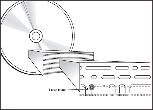
FIGURE 13.8
Pits and flats on a compact disc (CD)
Digital versatile discs (DVDs)
The DVD (digital versatile disc) is essentially the same size as a standard CD, but, whereas the standard CD holds up to 650 megabytes of stereo digital data, DVDs can optimally store up to 17 gigabytes. These discs are able to store far more data of high-quality video plus full bandwidth audio. How do they do this? By employing several different methods, including:
- A higher pit density rate for tighter tracks, and larger data area.
- Double-sided discs, actually two platters bonded back to back, increasing rigidity and minimizing laser focus problems due to warpage. This doubles the disc's storage capacity.
- Layers of data per platter, where the laser changes focus to access the different layers.
- More efficient error correction and video compression algorithms.
Not all DVDs hold 17 gigabytes of data because they aren't configured in the same way. Different configurations include:
- DVD 5: single sided, single layer; 4.7 gigabytes
- DVD 9: single sided, double layer; 8.5 gigabytes
- DVD 10: double sided, single layer; 9.4 gigabytes
- DVD 18: double sided, double layer; 17 gigabytes
All DVD players have the capacity to read all of the above formats. Some players require the user to remove the disc and turn it over because the manufacturers are too cheap to install separate lasers for both sides.
Many of today's larger sessions take up so much space that DVDs are used to store the data. Gone are the good old days when a simple CD would hold all your data.
Today's technology also relies on BLU-RAY discs. DVDs use a red laser to store and retrieve information, but a blue laser (hence the name BLU-RAY) has a shorter wavelength, allowing more data to be stored on a disc, even though it is the same size as a standard CD/DVD.
• What is the difference in actual sound between digital recording and analog recording? It is not unlike the difference between watching a movie filmed to analog and watching a video filmed to digital. You can see the difference, but try explaining it to someone. Differences include:
- With analog, some lower frequencies may be slightly accentuated, adding a ‘warmth’ not captured with digital.
- Peak levels can over-saturate an analog tape. Some engineers use this as part of their sound.
- A slight amount of high end may be lost on analog playback, simply due to limitations of analog tape. Digital recording processes audio with no perceivable loss.
- With digital recording, there is no signal loss due to tape shedding, no cross-talk, no track leakage, and no such thing as outside track degradation, commonly found on tracks 1 and 24 on analog.
- Analog copying will always have generation loss. There is no loss in digital because a copy is a clone of the ones and zeroes.
- Convenience. Today, with removable hard drives, a complete digital session can easily be taken from studio to studio. And there is no need to download. You can just work off the hard drive or memory stick.
- Traditionally, the engineer relied solely on his ears. Now he can see the waveforms and hear the sound to help him place it in the right spot.
• This is the end. Well, this is the end of this book. I hope that I was able to help you, the reader, a bit with your tracks and your recording. There are always more tips and tricks to learn, but most of them you will find out by experimenting, trying new things, and stealing new ideas off of other engineers.
Good luck in the studio.