
CHAPTER 7
Environmental Mechanics
Environments are not just containers, but are processes that change the content totally.
Marshall McLuhan
7.1 Introduction
Probably one of the most exciting tasks in creating art assets for a game is in the designing of the game world. From moulding mountains and placing trees on a terrain to designing a high-quality building interior the task can seem enormous and daunting at first. But before diving into the design, sometimes it is a good idea to sit back and examine the way things are in the real world—how shadows fall on the ground, how natural vegetation grows, what clouds look like, and all the little details inside buildings from stains on the carpet to the emergency exit sign.
When a player is in your game environment it should be the things that aren’t missing that they don’t notice that will make it more believable. For example, a hospital is not a series of corridors painted gray. There are so many little details, such as posters on the walls, rubbish bins, seating areas, and clocks on the wall that make the location feel like a hospital. One of the most difficult game environments for newbies to create is an outdoor landscape. At first trees can look clumped together and awkwardly positioned, mountains impossibly steep and oddly shaped, and a lack of correct shading and shadows.
This chapter is primarily about observing how things are and applying the rules of nature and architecture to develop game environments. It begins by examining fundamental map design, followed by terrain design, using camera effects for professional-looking scene rendering, and finishes up with the creation of some simplistic but highly effective weather systems.
7.2 Map Design Fundamentals
Map design for game levels is a sizable area of discussion and rules, and opinions on the best approach differ between genre and game developers. In this section, numerous ideas have been gathered from single-player and multiplayer 3D environments. Many of these suggestions have been taken from online discussions of designers at Valve, Ubisoft, Bungie, and a variety of other blogs and postings.
7.2.1 Provide a Focal Point
In a vast map it is a good idea to provide a focal point. This will act as the player’s goal location. If the terrain is rather desolate, like that shown in Figure 7.1, the player’s eye will be drawn to the dominating tower. In addition, because there are no other structures or objects in the area, the player will have no choice but to go toward the tower.
In a rather busy map, a large focal object that can be seen from most places in the level will assist the player with orientation. In Crysis, the player is placed in a thick jungle environment with many ridges. A crumbling and trembling massive mountain is shown in the distance as the obvious goal destination. Although at times the player can become disorientated among the trees, the mountain is visible from many positions, guiding and beckoning the player toward it.
7.2.2 Guide and Restrict the Player’s Movement
Although many game maps, whether they be outdoor terrains or inner city streetscapes, may seem endless, they are not. They are designed cleverly to draw a player along a certain path and restrict them access to parts of the map that aren’t actually there. For example, racing games such as Split Second blatantly guide the player along a path—the racing circuit! The player cannot jump the barriers along the sides of the road and drive off into the distance because there is no distance. What can be seen in the distance
FIG 7.1 A large map terrain with focal point.
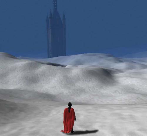
are billboards and 3D objects with very low polycounts. As the player can never get anywhere near these objects, having them in high definition is a pointless waste of computer memory.
Terrain maps, such as those encountered in Halo, subtly guide the player along a path where the sides are defined by steep inclines, vast drops, or endless water.
Enemy and reward placement also push the player into moving in a certain direction. Players of first person shooters know that they are moving toward their goal as the number of enemies increases. If there are nonplayer characters in a certain location, they are obviously guarding something important and the player feels the need to investigate. Even in children’s games where there aren’t such gruesome enemies, placing power-ups or extra point pickups along the path will keep them moving in the right direction.
7.2.3 Scaling
A recurring mistake newbie map designers make is in the scaling and detail of an environment and the objects within it. While some people are naturally talented at being able to create realistic-looking scenes, others
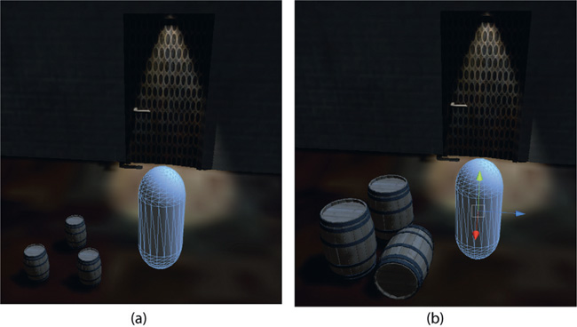
FIG 7.2 A scene with barrels of different sizes.
have to work at it. The most common error is to create a huge building, terrain, or city and place tiny little objects in it.
Don’t be afraid to resize an original asset. Look at the real world and the proportions of objects within it. Figure 7.2 demonstrates the unnatural-looking proportions of the barrels (a) and how they are better matched to the size of the player’s character (b). If there is a door in the scene, make sure it has correct proportions with respect to the player’s character. The same goes for stairs, furniture, trees, cars, and anything else in the scene.
7.2.4 Detail
As they say, “the devil is in the detail.”With this in mind, the same observational prowess used for proportions should be applied to map details. Wherever you are look around at the details that make the real world seem … well … real! Have a look at the way trees intersect with the ground. They don’t just look as though they are sitting on top of a pole driven into the ground. The terrain at the base is undulated from the tree’s roots, the grass is higher near the base where the gardener couldn’t fit the lawn mower, and there might be other interesting weeds or rocks scattered about. Even a pole that has been driven into the ground will eventually get taller grass growing at its base.
If you get a chance to look at a mountain or river view take note of where the trees and grasses are positioned and the color of the dirt. Mountains have a tree line beyond which trees do not grow because it is too cold. At this point you might find rockier ground and snow. Nearer the water
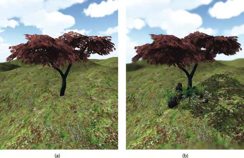
FIG 7.3 Two trees on a terrain (a) with no detail and (b) with detail.
you will find taller reeds and grasses. There is a reason why nature looks the way it does, and if you want your maps and terrain to be convincing you need to notice the little things.
Figure 7.3 contains a screen capture of two trees in a Unity scene: (a) just the tree added to a terrain and (b) the tree surrounded by detail with shadowing and other camera effects added. Note how the tree in Figure 7.3b is more convincingly part of the landscape than the one in Figure 7.3a. The idea is to strategically position objects and use special effects to remove the harsh boundary where one object meets another.
If you are creating a map based on a real-world landscape or building, go to that building. Sit and observe. Take photographs. If you’re mapping the inside of a hospital, go and have a look at all the things in a hospital that make it look and feel like a hospital. The colors, charts on the walls, trolleys, exit signs, and markings on the floor, to name a few, are all symbolic things that will keep the player immersed in your game environment.
7.2.5 Map Layout
Physical map layout differs dramatically according to the restrictions of perspective, narrative, and genre. Sometimes the logical structure of the story and the game play paths from start to end match with the analytical structure of the game environment and sometimes they don’t. For example, a game that is a simple from start to end consists of a linear story in which the player is moving through a story like an actor in a movie. Instead of being a key decision maker, the player will have a very linear game map in which the player moves from some starting position to an ending position. The level may convince the player that he has some control over his destiny with smatterings of game play; however, in the end, the real options are that the player dies or moves on at each challenge. Other open-type simulations such as SimCity have an evolving narrative that in no way at all dictates the physical layout of the map.
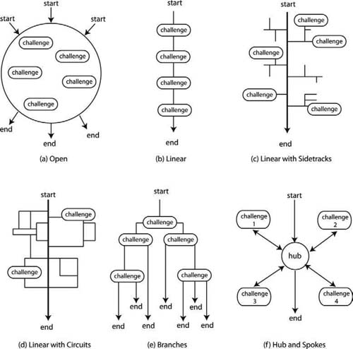
With this in mind, we examine several game-level design structures and discuss how the player’s journey through the story and the actual game world are related. While each of the ones presented illustrate a single game progression strategy, it is more the case for real games to use a hybrid of the ones presented to make for a more engaging player experience. Their generalization, illustrated in Figure 7.4 , herein is for academic purposes only.
Open
A truly open game map will have multiple starting positions and ending positions with numerous unordered challenges in between, as shown in Figure 7.4a . From a narrative point of view, The Sims is this type of game,
FIG 7.4 Game level design structures.
as you can start with any character you like, end the game when you like, and take on whatever challenges take your fancy along the way. The game environment of The Sims is also quite open in the way by which players can decide on the look, personality, and goals of their avatars and the layout and furnishing of their houses. The city map, however, is not open. It is physically a network structure with fixed positions of housing blocks and city buildings.
Physically speaking, the EVE Online maps are open with a variety of starting positions, numerous ways of traveling from one location to another, many unordered challenges, and multiple places to end/complete your journey. The players’ choices in these types of games are vast. Of course the game map isn’t one large infinite mesh, as it would be too big to process, but a series of minimaps cleverly linked together to give the impression of immeasurable universes.
Linear
Most games based around a story are linear; that is, they have a start, a journey, and an end (shown in Figure 7.4b ). Players typically accompany their character, the hero, through a series of carefully crafted challenges to the end. The start is always the same, the journey is always the same, and the end is always the same. In terms of a map it means a game environment in which there is only one path to travel to get from the starting position to the end. Along the way there may be puzzles, barriers, and enemies to battle, but the path is always the same.
To add some interest to the linear map, sidetracks (shown in Figure 7.4c ) can be added that can take players down a dead end path but provide extra bonuses or clues to aid in their progression along the main path. The danger here is that players could choose to skip an entire sidetrack unless encouraged to go down it because they have no other choice; for example, the main path might contain a locked door and the key is down a sidetrack.
Even more complexity is created when circuits (shown in Figure 7.4d ) are added off the main path. These provide players with opportunities to bypass parts of the main path. They can also disorient players and send them back to the beginning. Dungeons and Dragons and other maze-type games are created with both circuits and sidetracks. These maze games align perfectly with the narrative and map structures, as it is the sidetracks and circuits that dictate the maze’s physical layout.
Racing games are another example of a linear path with a circuit. The circuit takes the player from the start, around a track, and back to the start. The player’s journey is one that evolves according to the player’s racing skills; however, in the end, the game remains linear, as the start position, end position, and goal always remain the same.
Any game that has a linear story line similar to that in books and movies will require a linear map to ensure that players play through the story and live out the full life of their character. If the physical map has sidetracks and circuits, players will require a motivational story by which to choose to explore them. This can be achieved by placing side rooms or corridors off the main path that reward players’ exploration with extra ammunition, health, or other items that can assist their game progress.
Branching
A level with branching has the one starting position and multiple ending positions, as shown in Figure 7.4e . Narratively speaking, this means a story that starts in the same place but has multiple outcomes depending on the player’s game choices. These are difficult narratives to write, as a new story needs to be written for each branch. In addition, extra branches require extra artwork with respect to map designs. While a fork in the road might not literally represent a branch, it could mean that the player travels to another map or enters through a one-way door into another world.
If branching is used in physical terms in a game map it will mean that players can skip over a lot of game play and be content on their way to the end. On the other side, players can replay the game and take a different journey each time until they have explored all branches.
Spoke and Hub
Last but not least is the spoke and hub structure. This provides a progressive set of challenges by which the player must achieve challenge 1 to unlock challenge 2, complete challenge 2 to unlock challenge 3, and so forth. After each challenge, the player returns to the same central hub state. The single player path in Starcraft II is very much like this in which the player is located on a spaceship representing his home base; however, he must leave this hub to take on challenges. After each challenge, the player, if successful, has accumulated money and points and can upgrade his armada, weapons, and troops before proceeding to new unlocked challenges.
This level design structure requires numerous maps or map areas in which the challenges take place. Because of the progressing unlocking nature of the design, the player will eventually explore and experience all the game play and maps, unlike in a branching scenario.
As mentioned previously, today’s games are far more complex than the preceding level structures; however, they do include elements of one or more. What is important to keep in mind is that the game does not start with the game art or map levels. It must start with a conceptual design and story, as otherwise you might find yourself developing a lot of art assets that never see the light of day.
7.2.6 Other Considerations
Player Starting Position
How often have you loaded a game level and had your character looking at a wall or the ground? Can’t remember? Never? There is a reason why. The first thing players want to do when entering a game environment is to start the game. If they are facing a strange unexpected direction they will have little idea where to go next. It might be that they need only to turn around to see the door they need to go through or the corridor they need to walk down. But it is just a neater way of introducing the player to your level.
Flow
Flow in level design refers to the way in which players move from the beginning of the level to their goal. It is the level designer’s job to make the environment flow as best he can to challenge players, keep them moving toward their goal, and keep them engaged. Flow is mostly dictated by the physical layout of the map as described in Section 7.2.5.
Although in the end we all know the designer is herding the player down a certain path, this need not be revealed to the player immediately. Providing players with numerous paths to take allows them to make decisions in their game play about the way they traverse the map. This creates an illusion of freedom where there is none.
Game developers, Valve, and others use a variety of methods to control the flow through the game. In some areas you will want the player to run, in others to walk. Breaking the map into narrow areas that make the player feel confined, thus increasing tension in the game play, creates narrow flow.
Side rooms are another common technique in 3D environments. They give the map extra areas of interest but are dead ends. The player’s reward for exploring these areas is by way of extra weapons, power-ups, and other useful items. Side paths without reward don’t encourage the player to explore, and thus the exercise of creating these areas in the map becomes pointless and just extra work for the artists.
Trapping
Blocking the exit of a dead end after the player has entered is another way to create tension and panic. You could use this partway through a map or at the goal location. It should be obvious that if you do trap a player in part of the level he is able to get out. Most seasoned players would expect that if they become trapped it is the end of the level, they have some puzzle to solve, or very soon they will die or be rescued.
Use the 3D Dimension
Three-dimensional environments have height as well as depth and width. A map with various height levels allows for the player to get from one place to another via alternate routes. In addition, if players can see that there are multiple heights to a building or terrain they will expect to be able to get to these heights that could be used as resting or attacking positions.
Vantage Points
Ensure that your map has multiple vantage points where the player can hide or use as an attacking position. Some might be in better locations than others and will provide players with choice and variety in the way they choose to approach the game play.
If you are designing for a multiplayer environment, then multiple vantage points will ensure that play does not become predictable and ultimately boring. In the original Halo multiplayer mode, there is one map in which players can teleport between two spacecraft and shoot at each other across the void. There is a nice little nook off to the side of one of the ships with a cloaking shield in it. The same location looks out across the void and is also perfect for using the sniper rifle on your opponent when they are on the other ship. The cloaking field only starts a short time, and therefore it is wise to stand near the cloaking shield until your opponent comes into view on the other ship, pick up the cloak, and start shooting. As you cannot move and use the zoom on the sniper rifle at the same time, having played the map a few times, this strategy fails as your opponent knows where you are shooting from even when he can’t see you.
It is unavoidable that players will eventually explore and use up all the vantage points in a multiplayer map; however, the more variety provided, the longer the game play potential.
Map and level design are challenging for even the seasoned game developer and there are many books devoted to the topic. If you are interested in reading up on game and level design, start by reading some books dedicated to the subject, such as Fundamentals of Game Design, 2nd edition, by Ernest Adams.
7.3 Terrain
Terrains are meshes that make up the ground in an outdoor scene. They usually undulate in height and sport a variety of surface textures to make them look like a real outdoor desert, mountain, and even alien world scenes. The more detailed a terrain, the more polygons from which it will be made as additional vertices are required to give them a real-world smooth appearance. Because large elaborate terrains require a lot of processing, numerous tricks are employed to make the terrain look more detailed.
While there are many available tools for creating terrains, making them look real can be quite a challenge. The best examples come from nature.
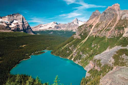
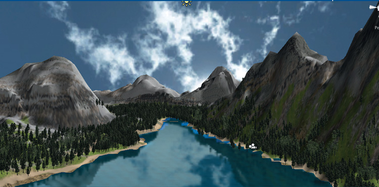
FIG 7.5 Lake Louise.
7.3.1 Drawing a Terrain
As you will find in the next section, although a terrain can be computer generated, the most detailed and realistic terrains are best created by hand. Throughout this chapter we work with the same terrain, adding differing effects to make it feel as realistic as possible. The terrain will be modeled on a photograph of Canada’s Lake Louise, as shown in Figure 7.5.
![]() Unity Hands On
Unity Hands On
Creating a Terrain
Step 1. Open Unity and create a new project.
Step 2. From the main menu select Terrain > Create Terrain. A large flat plane will appear in the scene.
Step 3. Add a directional light. When creating the terrain, a directional light helps show up the definition.
Step 4. To sculpt the terrain, select the terrain in the Hierarchy. A toolset will appear in the Inspector. The operation of the buttons is defined in Table 7.1.
TABLE 7.1 Terrain editor tools
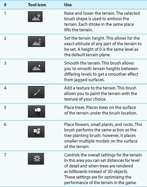
Step 5. For sculpting, select Tool 1. The brush size will affect the area of ground you can sculpt in one stroke and the opacity of the strength. A higher opacity will cause more of the terrain to be lifted in one stroke.
Step 6. Hold down the left mouse button over the terrain to start lifting the surface. At this stage begin with a basic outline of the Lake Louise area based on Figure 7.5, as shown in Figure 7.7 To lower the terrain, hold down the shift key with the mouse stroke.
![]() Note
Note
You might find it easier to replicate a real-world image if you place it on a plane inside the Editor to use as a reference, as shown in Figure 7.6
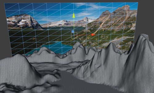
FIG 7.6 Inserting a reference photo into the Scene while editing.
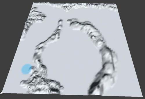
FIG 7.7 A basic terrain plan for Lake Louise.
Step 7. Using a combination of Tools 1, 2, and 3, sculpt and smooth the terrain into an approximate representation of the Lake Louise landscape as shown in Figure 7.8.

FIG 7.8 A terrain sculpted to represent Lake Louise.
Step 8. Once the basic terrain is constructed it can be textured. For texturing, seamless images are required. These images must be placed in the Project. Acquire these textures by searching online. An excellent seamless texture pack is available at http://aeonicdesign.ca/Textures/ Textures/AeonicTexturePack.zip.
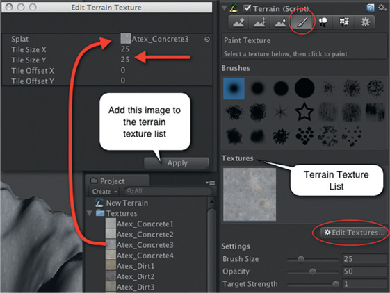
Step 9. Click on Tool 4 to select the terrain painting brush. Before you can start coloring the terrain, the images need to be loaded as terrain textures. Select the Edit Textures button as shown in Figure 7.9 and select Add Texture. A pop-up window will allow you to select the image and its tile size. The larger the tile size, the more terrain a single copy of the image will cover.
Step 10. Select a texture to be the first and click on Apply to add it to the terrain texture list. Because the first texture added will cover the entire terrain automatically, picking an image that represents the most common surface color saves a lot of texturing work later.
Step 11. Add more images to the texture list and use the brush size, opacity, and target strength settings to paint the terrain. The opacity value sets how much of the underneath texture mixes with the newly added texture, and the target strength is how much of the added texture is placed on the surface. A low opacity will allow a lot of the underneath color to show through. A low target strength will add very little of the current texture to the surface. Experiment with these values to get the effect right. If you make a mistake it is simple enough to recolor over the mistakes.
FIG 7.9 Adding a terrain texture.
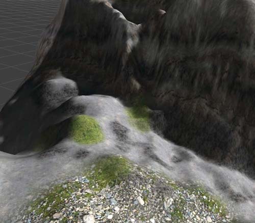
Wherever trees will be placed, think about the final effect. If you want the trees to look lush and forest like, a ground color similar to the trees will make it look denser than it is. An example of the painted terrain is shown in Figure 7.10.
Step 12. Trees can also be painted onto the surface using Tool 5. Currently, there are no trees in the Project. Download the terrain assets package available at http://unity3d.com/support/resources/assets/terrain-assets and import into your project.
Step 13. Trees are added to the tree brush in the same way images are added to the textures. Add a couple of appropriate trees.
Step 14. Examine the photograph of Lake Louise. Note how the trees do not cover the entire landscape? Obviously they will not be in the lake area but they are thickest near the water and thin out to a distinct level after which the odd tree is found. In the real world, elevation and soil content at heights make it inhospitable for trees. Therefore, mimicking nature in this way makes the terrain look better.
Step 15. In the picture of Lake Louise there is also a thin line of sand around the edge of the lake. Once you have added the trees, take a small texture painting brush, select a light sand color, and add this
FIG 7.10 An example of a painted terrain.
detail. It will lift the tree line and create shore for the water of the lake as shown in Figure 7.11.
Step 16. From the main menu select Assets > Import Package > Water. Choose the Pro version if you have it; otherwise Basic will do.
Step 17. Locate the Daylight Water prefab. It will be in the Standard Assets folder in the Project. Drag it onto the terrain. At first it will appear as a small blue circle. Select it in the Hierarchy. Press R to resize and drag the resizing axes in the Scene to make the water the same size as the lake area. It is okay if the water intersects with the terrain. If the water is at the exact same y position as the terrain there will be a rendering conflict between the ground of the map and the water. Lift the water up slightly in the y direction to eliminate this.
Step 18. Import the Character Controller package.
Step 19. Add a First Person Controller to the Scene. Play and you will be able to walk around and take a first-hand look at your handiwork. At this level you may notice a lot of little details you’ve missed.
Step 20. When playing, if you cannot see the background mountains increase the Main Camera’s Far Clipping Plane to 5000. As you want to portray a feeling of vastness to the player in this environment, having the background mountains pop in and out of view as the player moves spoils this effect.
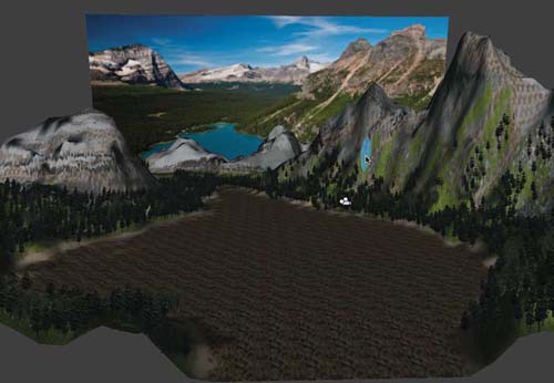
FIG 7.11 Trees and shoreline added to Lake Louise terrain.
Step 21. Lake Louise is a vibrant blue color. The water you’ve added might not be quite right. To change this, select the Water in the Hierarchy and change its Reflective Color to a more suitable blue as shown in Figure 7.12.
Step 22. Last but not least, import the Skybox package.
Step 23. Select Edit > Render Settings from the main menu and set the Skybox Material variable in the Inspector to the skybox of your choice as shown in Figure 7.13.
Step 24. Remove the plane containing the real photograph of Lake Louise and play to enjoy your new creation. An example is shown in Figure 7.14a.
Step 25. One final step to perform is to create shadows on the surface of the terrain. Ensure that you have at least one directional light in the scene. Select Window > Lightmapping from the main menu.
A lightmap is a generated texture laid over the terrain like a cloth that contains black spots where shadows should appear. It is generated based on the location of the lights in the scene and how rays cast from them hit (or don’t hit) the terrain. Objects in the way of the light rays cause black spots on the lightmap.
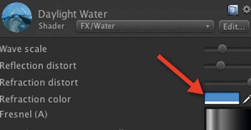
FIG 7.12 Changing water colors.
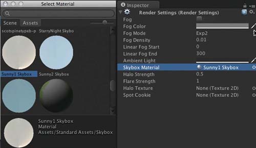
FIG 7.13 Adding a skybox.
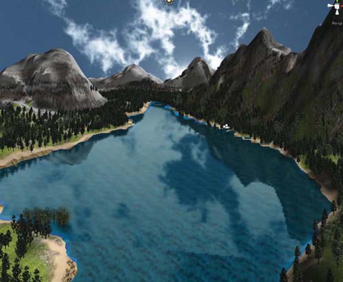
FIG 7.14 Lake Louise as interpreted by the author.
Step 26. Select the directional lights in the environment and ensure that they have the value for Shadow Type set to Hard or Soft Shadows in the Inspector.
Step 27. In the Lightmapping window with the Object tab selected, click on a directional light in the Hierarchy to add.
Step 28. Select the Bake tab and click on the Bake button.
The term baking in games and computer graphics refers to creating a texture of an image and adding it to a mesh in cases where sometimes the texture might be dynamically created. For example, dynamic shadows that are generated and therefore can change in the game environment as it plays are not baked. Shadows that are baked into the environment have become part of the environment’s textures and therefore cannot change during game play.
The terrain baking procedure may take some time. A progress bar will appear in Unity. At this time it is best to go and make a cup of coffee. The baking screen is shown in Figure 7.15.
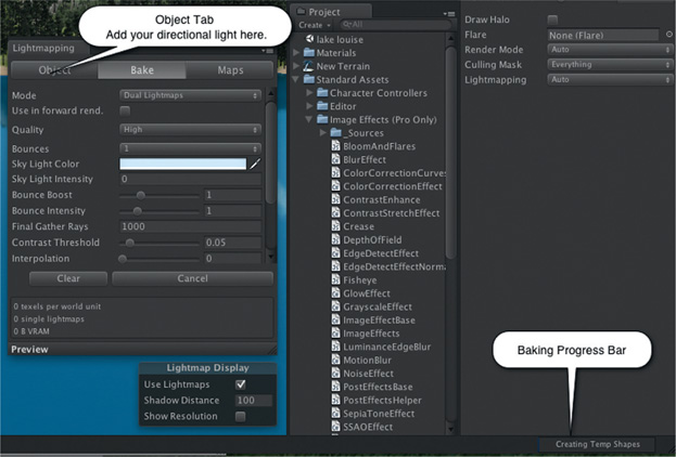
FIG 7.15 Creating a lightmap for a terrain.
![]() On the Web
On the Web
For more information on lightmapping in Unity, visit http://unity3d.com/ support/documentation/Manual/Lightmapping.html. Lightmapping before and after images of the Lake Louise terrain are shown in Figure 7.16. Note how the trees now cast shadows.
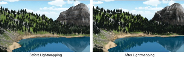
FIG 7.16 Lake Louise terrain before and after lightmapping.
7.3.2 Procedural Terrain
Procedural terrain is that generated by a computer algorithm. Most of the methods are based on fractals. A program is written that defines the vertices of a mesh and recursively raises and lowers the points to create altitude. One simple terrain producing method is the midpoint displacement algorithm.
This algorithm works starting with a flat surface. It divides it in half and then raises or lowers the middle point. Then each half is halved and the midpoint of these is raised or lowered. A 2D representation of this progression is illustrated in Figure 7.17.
Another popular procedural terrain generation algorithm is the Diamond Square method illustrated in Figure 7.18. Starting with a square mesh with a power of 2 + 1 number of vertices in width and height,1 for example, 257,
FIG 7.17 Midpoint displacement on a 2D line.
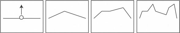
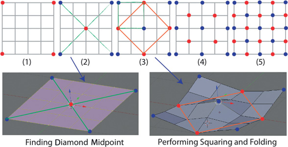
FIG 7.18 The Diamond-Square algorithm.
513, 1025, all four corners are set to the same initial height [Figure 7.18 (1)]. The second step, the diamond step, locates the central vertex where the diagonals from the initial vertices intersect. Step 3 creates squares between the central point and previous initial points. Now imagine fold lines between the red points and the height values assigned to the blue points shown in green in Figure 7.18. Blue points determine height, and green lines are where the mesh is allowed to fold.
The Diamond-Square method continues creating diamonds to find midpoints and squares for lowering and raising until all points in the grid have height values associated with them.
![]() Unity Specifics
Unity Specifics
Unity has a terrain editor plugin that employs the Diamond-Square algorithm for creating realistic-looking terrains without all the hard work of sculpting and painting. You can check it out by downloading the package from http://unity3d.com/support/resources/unity-extensions/terrain-toolkit.
Perlin Noise is another popular algorithmic way to generate landscapes. It is used in the next workshop to produce a natural-looking terrain from a plane object in Unity.
![]() Unity Hands On
Unity Hands On
Generating a Terrain Procedurally
Step 1. Create a new Unity project and import the Character Controller package.
Step 2. Add a plane to the scene and a first person controller (FPC). Position the FPC just above the plane and add a directional light as shown in Figure 7.19. Scale the plane’s x and z size to 10.
![]() Note
Note
If you want a smoother, more detailed terrain, you will need to use a plane with more vertices than the one supplied with Unity. To do this, using Blender or your favorite 3D modeling program, create a plane and apply subdivisions to give it the number of polygons you desire.
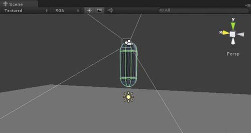
FIG 7.19 A plane and FPC for starting the project.
Step 3. Select the plane in the Hierarchy and remove its Mesh Collider component in the Inspector. We will add a new one shortly after its terrain heights have been modified.
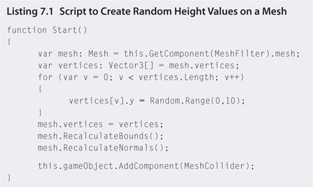
Step 4. Create a JavaScript file called makeTerrain.js. Add the code shown in Listings 7.1.
Step 5. Attach the script to the plane.
Step 6. Play. The terrain will have random heights across its surface. Note that the Mesh Collider is added after the heights have been set. This will ensure that the FPC does not fall through.
After the mesh vertices are modified in the y direction for height, the bounding volume and normals are recreated. The bounding volume and normals are recreated. The bounding volume is used by the game engine to improve the processing of geometrical operations such as collision detection and overlap. The reason being that in the first instance, computing overlapping volumes is easier than lower level collision detection. Before exact collisions are calculated, determining if there might be a collision between two objects is more efficient with bounding volumes.
In addition, the plane’s normals are also recalculated. Because the plane’s mesh has changed shape, the normals must be adjusted for the new vertex values for the mesh to be shaded and shadowed correctly.
Using a random function to determine height is not a realistic way to produce rise and fall in a terrain, as the height can change erratically with each vertex. At small height values it might look all right, but try changing the random range from 0 to 50 and the surface of the plane will become very jagged.
Step 7. To create smoother rises and falls in a surface, a mathematical curve such as Sine or Cosine can be used. Modify makeTerrain.js to reflect the changes shown in Listing 7.2.
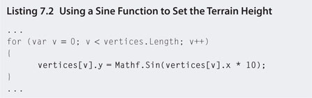
Step 8. Play. The shape of the sine wave will be visually evident. The terrain will be smooth, but too uniform to replicate a natural landscape.
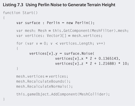
Another way to create a landscape procedurally is to use Perlin Noise, a pseudo-random mathematical algorithm that provides smooth gradients between points. This is the method used for landscape generation in Minecraft.
Step 9.Downloand Chapter Seven/Perlin.js from the Web site. Add the file to your Project inside a new folder called Plugins.
Step 10.Modify makeTerrain.js to that shown in Listing 7.3.
![]() Note
Note
Perlin Noise
Perlin Noise is the same algorithm used in Photoshop for generating the Render Clouds filter. The image created by Perlin Noise is grayscale, where black indicates the lowest altitude and white the highest, as shown in Figure 7.20a.
In fact, you can create a procedurally generated terrain in Unity (shown in Figure 7.20b) by (1) adding a terrain, (2) getting the flat terrain texture with Terrain > Export Heightmap, (3) opening this texture with Photoshop, (4) applying Photoshop’s Render Clouds filter, (5) saving the texture in the same raw format, and (6) selecting Terrain > Import Heightmap in Unity to load the heights.
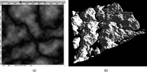
FIG 7.20 (a) A texture created with Photoshop’s Difference Clouds Filter. (b) A Unity Terrain with the same texture used as a heightmap.
The difference in using a random number for the height and Perlin Noise is illustrated in Figure 7.21.
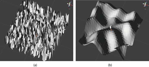
FIG 7.21 (a) A terrain with random height values. (b) A terrain with Perlin Noise height values.
7.3.3 Procedural Cities
Generating realistic cities with code is more challenging than landscapes. While terrain can reuse trees, rocks, grass, and dirt textures, reuse of the same building or random street structures can look unrealistic. In the same way that fractals can be used for generating terrain and layout, they too can be used to create objects on the terrain such as trees and buildings.
A Lindenmayer system or L-system is a fractal algorithm used commonly for generating trees as it has a natural branching structure. An L-system is constructed from a string representing drawing commands. The string is built through an iterative process where parts of the string are replaced with other strings. An L-system begins with an axiom and a set of rules thus:
F -> F+F
Starting with the axiom as the original string, each character in the string matching a rule is replaced with the rules string. Therefore, after one iteration, the aforementioned becomes:
F+F
Then, each F in the new string is replaced by the rule in the next iteration, thus:
F+F+F+F
Note that only the character F is replaced, and with F + F, the already existing + carries over to the next string. This is illustrated in Figure 7.22.
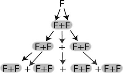
FIG 7.22 L-system rewriting.
After numerous iterations, a string such as F + F + F + F is then interpreted by a drawing algorithm in which the letters represent lines and the + a turn to the right (if - is used it means turn to the left). It is reminiscent of turtle graphics in which a cursor on the screen is given commands to draw a line, turn right, draw another line, etc. The turn angle is preset. Let’s say F represents draw a straight line and + represents turn 900. The drawn result would be a square as shown in Figure Figure 7.23.
In addition to drawing and turning, an L-system can contain push and pop points. These are represented by square braces ( [,] ). When the drawing algorithm encounters these points it remembers its location on a [, keeps drawing, and then returns to the remembered location when it encounters a ]. For example, F[+F]F where + is 45 ° would produce the L-system shown in Figure 7.24.
L-systems become more complex with the addition of extra rules such as the one shown in Figure 7.25. This is a famous fractal called the Sierpinski triangle.
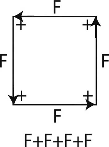
FIG 7.23 An L-system that draws a square.
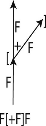
FIG 7.24 An L-system with remembered locations.
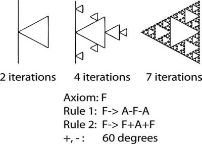
FIG 7.25 Sierpinski triangle.
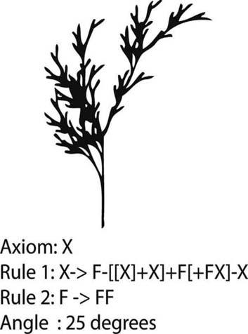
FIG 7.26 An L-system tree.
Natural and familiar shapes can be created with L-systems (as shown in Figure 7.26).
To produce a procedural map, at least two types of L-systems are required: one for drawing the map layout with the transportation routes and one for creating the buildings. Figure 7.27a illustrates a simple street map using the same L-system as the one for the tree in Figure 7.26 with the angle set to 90°. Figure 7.27b shows how an L-system can be used to create buildings. Simple lines are replaced with 3D blocks. The result in the three iterations shown hints at how compelling a fully finished building could look.
![]() On the Web
On the Web
Procedural City Generator
The aforementioned techniques for generating a city procedurally come from the research work of Muller and Parish. Their approach has been packaged into the CityEngine software—a 3D modeling package built purposely to generate vast city landscapes. A free trial can be downloaded from http://procedural.com
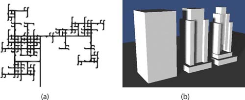
FIG 7.27 (a) An L-system street map and (b) L-system progression of a building.
Although the programming of an algorithm to build a 3D L-system city is beyond the scope of this book, it is possible using Perlin Noise and existing building models to generate a city. This is the topic of the next workshop.
![]() Unity Hands On
Unity Hands On
Procedural Cities
Step 1. Create a new Unity project and import the Character Controller package.
Step 2. Add a plane to the scene and an FPC. Position the FPC just above the plane and add a directional light as shown in Figure 7.19. Scale the plane’s x and z sizes to 10.
Step 3. Download Chapter Seven/Perlin.js from the Web site. Add the file to your Project inside a new folder called Plugins.
Step 3. Create a JavaScript file named makeCity and reuse the code from Listings 7.3.
Step 5. Play. What you should have is the heightened terrain from the previous example. Now instead of heights we will add buildings.
Step 6. If you put a print statement inside the for loop in makeCity.js and print out the height values being assigned to the plane, you’ll notice they range between -4 and 4. We will use these values to assign buildings instead of terrain heights. Go to Turbosquid and download eight models of various types of houses and buildings. You will also find eight building models already downloaded from Turbosquid on the Web site as Chapter Seven/buildings.zip.
Step 7. Add the buildings to the Project.
Step 8. Add each building into the Scene and position them on the plane. Because different artists created them, their scaling will be different. Resize and rotate each building as you see fit such that they have reasonable relative sizes and orientations.
Step 9. Create eight prefabs in the Project—one for each building. Drag each building out of the Hierarchy and onto its own prefab.
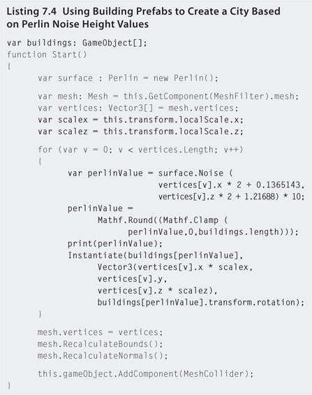
Step 10. Modify makeCity.js to that in Listing 7.4.
Step 11. Select the plane in the Hierarchy and find the makeCity script in the Inspector. Set the size of Buildings to 8 and drag and drop each building prefab onto the exposed building array elements in the script. Note that you can have any number of buildings and the code will adjust for it.
Step 12. Play. The result will be a small city as illustrated in Figure 7.28.
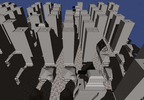
FIG 7.28 A procedurally generated city.
![]() Note
Note
As Perlin Noise creates smooth regions that graduate between white and black when drawn as a grayscale, you can use these values to determine the city density at these locations. For example, white might represent high density and black low or no density. Where the map is densest use the skyscraper type building models and where it is lower use small houses. This will create a relatively realistic city.
7.3.4 Infinite Terrain
Infinite terrain or endless terrain is a form of procedurally generated landscapes. It uses a mathematical equation and the player’s current position to create the landscape as the player moves. Small parts of the map are created as needed based on the player’s visible distance. Any map outside the visible range is not generated and therefore not a load on computer memory.
To create undulation of a terrain, a mathematical formula is used for determining the height based on the x and z positions on the terrain for which there will always be a y value no matter the x and z values. For example, the sine or cosine functions can produce values for infinite values of x and/or z and the result used as the y value.
The beauty of using a formula is that the result of y for any x and z values is always going to be the same, thus assuring us that if we return to a previous location on the map that was destroyed after we left but recreated on our return, the height remains the same. In addition, the terrain can be infinitely large, generated entirely by the computer. This means a human artist is not required to constantly churn out more and more of the landscape. Terrain textures, trees, rocks, and other model objects are used over and over again.
Perlin Noise makes for a good choice in infinite terrain generation applications as it produces a random yet smooth undulating surface.
![]() On the Web
On the Web
An Infinite Terrain Generator
Developing an infinite terrain generator is a tricky business and as such is beyond the scope of this book. However, a generous Unity forum member going by the name of Quick Fingers posted a package for one on the Unity Web site. For this book, the code has been modified to use Perlin Noise and places trees and different textures on the terrain at varying heights. You can download the project from the Web site as Chapter Seven/InfiniteTerrain.zip.
On opening the Infinite Terrain scene, you will find a Terrain Generator object in the Hierarchy. Select this to modify the terrain’s parameters in the Inspector. You will notice that different terrain textures are used for different altitudes. When rendered, the contrast between the textures is evident. They are not blended in the same way as the Unity paint on textures in the Unity Terrain Editor. This is because they are placed on the mesh live as the game is playing and the mesh is generated. While a blending algorithm could blend the textures to make them fit together better, it would slow down the generation of the terrain.
As you move around the map watch the action in the Scene. Only the parts of the map that are within sight of the player’s camera are generated and drawn. As you move around, as parts of the map become out of sight, they are destroyed. This keeps the memory usage low and allows you to move infinitely in any direction totally oblivious to the small mesh your character is standing on.
A view of the infinite landscape is shown in Figure 7.29.
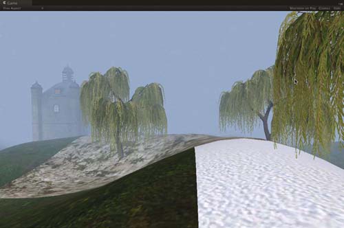
FIG 7.29 An infinite landscape generated in Unity.
7.4 Camera Tricks
Cameras are the player’s eyes into the game environment. What the camera sees is projected onto the computer screen. Before each pixel is drawn the game developer can add special treatments to the properties and colors of the pixels by attaching scripts to the camera. This allows for the creation of many different visual effects. For example, a blur effect can be added to the camera when the player is underwater to give the illusion water is in the player’s eyes or the scene can be rendered in sepia to make it look like an old-time movie.
Many of the following effects come from the domain of image processing and photographic postproduction and can be found readily as filters in Adobe Photoshop. They have found their way into gaming as a way of enhancing the player’s visual perception of the environment. Some of the wide ranges of camera effects available in Unity are shown in Figure 7.30.
FIG 7.30 A sample of the camera effects available in Unity.
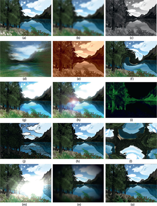
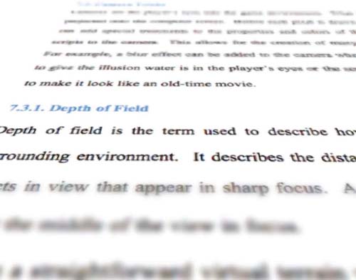
FIG 7.31 A shallow depth of field.
7.4.1 Depth of Field
Depth of field is the term used to describe how an optical lens focuses on the surrounding environment. It describes the distance between the closest and the farthest objects in view that appear in sharp focus. A shallow depth of field has items only nearest the middle of the view in focus as shown in Figure 7.31.
As the human eye is a lens it also projects an image with a depth of field. Unlike in a straightforward virtual terrain where all objects are in focus, for humans, our real world tends to become fuzzy in the distance and sometimes close up. Adding a depth of field effect to the game view camera gives the scene a higher feel of realism, quality, and 3D effect. The depth of field effect in Unity is shown in Figure 7.30.
7.4.2 Blur
Blur is an effect that makes the entire image look out of focus. It can be used effectively to simulate the look of being underwater.
Setting a pixel’s color to the average color of its neighbors creates a blur effect. Within a certain radius all pixel colors are sampled, added together,
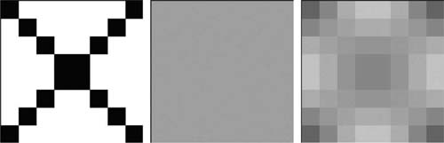
FIG 7.32 Average blur versus Gaussian blur.
and then divided by the number of pixels. Each pixel is then given the same average value. Another familiar blur is Gaussian blur. It adds the pixel colors together to determine an average; however, pixel colors in the center of the selection are given more weight and therefore the blur appears to radiate outward. The difference in the effects is illustrated in Figure 7.32.
The blur effect in Unity is shown in Figure 7.30.
7.4.3 Grayscale
Grayscale reduces colored images down to variations of gray such that it looks like a black and white photograph. The simplest method for creating grayscale from color is the average method that takes the red, green, and blue components of a pixel and divides by three. This new value is reassigned to the original pixel. The lightness method sets a pixel value to the average of its highest and lowest color components. For example, if a pixel had an RGB value of 255,45,60, the highest value 255 and the lowest value 45 would be added together and divided by two. The final method, called luminosity, gives the best grayscale result by cleverly weighting the green value to account for human eye sensitivity. The luminosity algorithm is 0.21 R + 0.71 G + 0.07 B.
Unity’s blur effect is illustrated in Figure 7.30.
7.4.4 Motion Blur
Motion blur is an effect used to make something look like it is moving rapidly or to give the player a dreamy view of the environment. The pixels appear to streak across the page in the direction of the motion. In addition, objects can have ghosting effects surrounding them. The effect is achieved by partially leaving the previous frame on the screen while rendering the next one. This effect is also useful in persuading players that their character FIG 7.32 Average blur versus Gaussian blur. is disorientated as a result of being drugged or in a dream state. Motion blur is illustrated in Figure 7.30. Motion blur is often used in racing games when the scenery is moving past the camera quickly and in first and third person games when the character is moving quickly.
7.4.5 Sepia Tone
Sepia tone is the brownish tinge seen on old photographs and film. It is achieved using an algorithm similar to that used for grayscale. The red, green, and blue values of a pixel are reset based on the addition of percentages of their original color components thus:
Sepia Red = R × 0.393 + G × 0.769 + B × 0.189
Sepia Green = R × 0.349 + G × 0.686 + B × 0.168
Sepia Blue = R × 0.272 + G × 0.534 + B × 0.131
You may have seen sepia tone used in the cut scenes of games where an event is taking place in the past or in actual environments when the game is set in the past. The Sims Medieval uses sepia tones for its world map and storytelling still shots.
Sepia tone applied in Unity is demonstrated in Figure 7.30.
7.4.6 Twirl
The twirl effect takes a portion of the screen pixels and wraps them around a whirlpool-type motion as shown in Figure 7.30. This effect is usually seen in film footage or cut scenes when one scene is crossing into another. A similar effect can be found in vintage Batman animated cartoons (and other similar productions) where the bat insignia was circled in and out in between acts.
7.4.7 Bloom
Bloom is the glow effect seen around light sources that extend into the environment. It makes an image look overexposed and the colors washed out. It is more prominent the stronger the light source and the dustier the environment.
An example of the bloom effect being used in Unity is shown in Figure 7.30.
7.4.8 Flares
Flares are bursts of reflected and refracted light. The most commonly known flare is a lens flare, which causes a series of translucent, rainbow, bright circles on an image from light passing through a camera lens as shown in Figure 7.30. It is often used in games to give the player the illusion they are looking into the sun when facing skyward.
Flares can also be caused by bright light passing through partially transparent materials such as glass or reflected off shiny surfaces such as polished metal and water.
7.4.9 Color Correction
Color correction does as its name suggests. It takes certain colors occurring in an image and changes them to another color. For example, a hill covered in green grass could be made to look like a hill of dead brown grass by replacing the color green with brown.
In games, color correction can be used for rendering night vision effects, changing most of the colors to green as shown in Figure 7.30. Each R, G, B value is matched with a replacement R, G, B value. At any time, color correction, as with all these effects, can be turned off. Using this method you could simulate the well-known Splinter Cell game play where the main character can use his night vision goggles in dark environments, which changes what the player sees on the screen at a press of a button.
7.4.10 Edge Detection
An edge detection algorithm scans an image for areas where pixels in close proximity contrast in color. Because the difference between individual pixels would produce erratic effects, the algorithm must determine if a pixel is on the edge of an area of similar color by looking at its surrounding pixels. This creates a picture that looks like a sketched outline.
The optimal approach to edge detection is the Canny edge detection algorithm. Further technical details about it can be found at http://pages.drexel.edu/~weg22/can_tut.html.
The edge detection algorithm in Unity outlines all objects with a black line as shown in Figure 7.30.
7.4.11 Crease
Creasing is a nonphotorealistic effect that increases the visibility of game world objects by drawing a line around the silhouette, much like in comic book images. In a busy game environment with many objects, such as buildings and trees, drawn from similar colors and tones, objects can become difficult to distinguish. By applying creasing at differing depths, the line can distinguish between near and far objects.
The example from Unity shown in Figure 7.30 has drawn a line around the top edge of the mountains, thus distinguishing them even more from the skybox.
7.4.12 Fish Eye
The fish eye effect produces an image as seen in a spherical mirror or through a wide-angle lens. The image produced is hemispherical in nature. Depending on the amount of curvature in the image, it can look completely distorted and inside out as the one from Unity in Figure 7.30. When used in a less exaggerated manner, the effect widens the field of view, showing more of the scene than is in the camera’s normal range. However, to fit in the extra parts of the image, at the outer edges the scene starts to bend with the effect, becoming more exaggerated the farther it is from the center.
7.4.13 Sun Shafts
Sun shafts are produced by a bright light source being partially occluded and viewed when passing through atmospheric particles. For example, sun shafts are prominent after a sun shower when the sun is partially blocked by clouds and the air is heavy with moisture. You might also imagine sun shafts coming through a dusty attic window or in between the trees in a rainforest.
This effect as produced in Unity is shown in Figure 7.30.
7.4.14 Vignette
Vignetting is an effect used to focus the viewer’s attention on an object in an image by darkening and/or blurring the peripheries. The start of each James Bond movie provides an example where the viewer is looking down the barrel of a gun. The view is restricted to a small circle in the middle of the screen and the supposed inside of the gun barrel sets the outside to black. Vignetting need not be this dramatic. Instead of the edge darkening abruptly, it might fade to black instead.
In a game view, a vignette can focus the player’s attention on an area of the game environment or be used to restrict the player’s view. Unity’s vignette script is illustrated in Figure 7.30.
7.4.15 Screen Space Ambient Occlusion (SSAO)
The SSAO effect approximates shadowing in from ambient light based purely on the image produced by the camera. As it is a postproduction effect, it does not rely on a light source or on information about an object’s materials to calculate shadows. It works with the image to emphasize holes, creases, and areas where objects meet. For example, without any lighting in a game environment to provide dynamic or baked shadows, trees stand on the terrain but somehow look disconnected and not in contact. SSAO provides a dusting of shadow around these connection points such that these types of intersections don’t appear unnatural.
The use of SSAO in Figure 7.30 brings more depth and natural effect to the image, providing shadowing in and under the rocks and grass and between the leaves of the tree.
This section examined a variety of camera effects. These are added to the rendering postproduction after the camera has determined the scene. As such they can require a great deal of computer processing and are not recommended for use on platforms without sufficient graphics processing capability (like many mobile devices).
As Unity only provides these effects with the Pro version, they have not been fully elucidated here. However, the interested reader is encouraged to read Unity’s own documentation found at http://unity3d.com/support/documentation/Components/comp-ImageEffects.html.
7.5 Skies
There are a number of ways to create skies for a 3D game environment. The easiest way is to set the background color of the camera to blue. Alternatively, if you want to include fog, setting the fog color to the background color gives the illusion of a heavy mist and provides for landscape optimization as discussed in Chapter Two.
To get clues as to what a game environment sky should look like, we can just look up. Our sky is more than a blue blanket covering the earth. Its colors change throughout the day with the position of the sun, the quality of the air, the weather, and the longitude and latitude.
The daytime sky appears blue due to a phenomenon known as Rayleigh scattering (named after a physicist of the same name). As sunlight enters the earth’s atmosphere, it interacts with the air and dust particles, which bend the light and scatter the different colors across the sky. The color that is scattered the most is blue. At sunset, the sun’s rays enter the atmosphere at different angles relative to the viewer and cause more yellow and red light to be scattered. Rayleigh scattering is caused by particles smaller than the wavelength of light.
Particles that are comparable or larger than the wavelength of light also scatter it. This effect is described by the Mie theory, developed by physicist Gustav Mie. The theory explains how particles such as water droplets affect the scattering of light. The Mie theory elucidates why clouds are different shades of gray and white.
Another factor influencing the look of the sky is turbidity. Turbidity describes the amount of suspended solid particles in a fluid. In the sky, turbidity relates to the number of dust, ash, water, or smoke particles in the air. The density of these particles affects both Rayleigh scattering and the Mie theory as it also adds to light scattering. For example, when the earth experiences a large volcanic event, which spews tons of dust and ash into the air, sunsets appear to last longer and have more vivid colors.
The following sections examine two ways to create skies: one that uses a simple texture and the other that considers the physical theories of light and air interaction described earlier.
7.5.1 Skyboxes
The most common method of creating a sky with cloud textures is to use a skybox. This is essentially an inside-out cube placed over the camera with seamless images of the sky rendered on it. Because it only requires six planes and six textures, it is a relatively cost-effective way to create a convincing-looking sky. The six textures are referred to by their position on the cube: up, down, front, back, left, and right. An example skybox is shown in Figure 7.33.
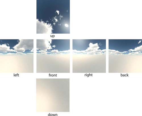
FIG 7.33 The six textures making up a skybox.
Skyboxes
Unity comes with a number of skyboxes. To use these, you must import the skybox package by selecting Asset > Import Package > Skyboxes.
To apply a skybox to a scene, select the Main Camera and location of the Camera component in the Inspector. Set the Clear Flags value to Skybox. Select Edit > Render Settings from the main menu and, in the Inspector, set the Skybox Material to the one you want. In the Game, the chosen skybox will display.
To use your own skybox, create a folder on your computer containing each of the skybox textures. Name the textures after the folder name and suffix with their position. For example, if your folder were called sunset, then each of the images would be sunset_up.jpg, sunset_down.jpg, sunset_front .jpg, sunset_back.jpg, sunset_left.jpg, and sunset_right.jpg. Drag and drop this folder into the Project. Your custom skybox will now be available in the Render Settings.
7.5.2 Sky Domes
A sky dome, as the name suggests, is a dome mesh placed over the environment with a sky texture stretched across the inside surface as shown in Figure 7.34.
The sky dome is attached to the player’s camera, like an oversized helmet, such that it moves everywhere with the player. Unlike a real helmet, it does not rotate as the camera looks around—it just translates, ensuring that it is always projecting a sky with the player at the center. This ensures that the player never sees the edges of the dome. If the dome is not big enough, as terrain and scenery come into view, they will pop through the dome edges. Strategic sizing and positioning of the dome are critical to ensure that this does not occur.
Because the UVs of the sky dome are inline in arcs across the sky mesh, it’s simple to scroll textures across the mesh in the same way the textures are scrolled across a plane in Chapter Two. This makes it easy to add cloud textures to the dome and move them across the sky.
In the next workshop, a sky dome package created by Unity Developer Martijn Dekker 2 will be used to place a sky, complete with moving clouds and a sun, around a first person controller. Dekker has taken into consideration Rayleigh scattering and the Mie Theory to produce a truly exceptional sky dome.
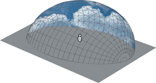
FIG 7.34 A sky dome.
![]() Unity Hands On
Unity Hands On
Sky Domes.
Step 1. Create a new Unity Project. Import the Character Controller and Terrain Assets.
Step 2. In the scene add a Terrain. Style and texture as you see fit.
Step 3. Add a First Person Controller to the Scene. Position the player over the terrain.
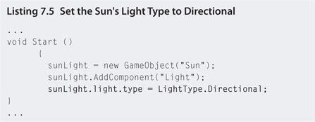
Step 4. Because the sky dome object you are about to add generates its own sun, you do not need to add a directional light; however, you will need to change the light type to Directional. Modify skyDomeScript.js with that in Listings 7.5.
Step 5. Play to ensure that the player isn’t falling below the terrain. Reposition the player as necessary.
Step 6. Download Chapter Seven/SkyDome.unitypackage from the Web site and import into Unity.
Step 7. From the skydome folder created in Project, after the import, drag and drop the SkyDome prefab into the Hierarchy. The SkyDome will appear as a large white sphere in the Scene.
Step 8. Select the SkyDome object in the Hierarchy. Locate the Skydome Script component in the Inspector and set the Player attribute to the First Person Controller as shown in Figure 7.35.
FIG 7.35 The Skydome Script component and setting the Player attribute.
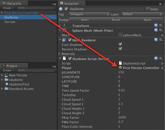
Step 9. Play. A sky dome with clouds will fill the sky. The sky dome has an internal clock, which will cause the sun to move across the sky, making for a day, sunset, night, and sunrise cycle. There are two layers of clouds whose settings are independent.
In the SkyDome Script settings in the Inspector, you can modify the specific sky dome properties for a variety of effects. These include:
- JULIANDATE: Sets the day of the year (with January 1st being day 1)
- LONGITUDE and LATITUDE: Player’s position coordinates on the surface
- TIME: The time of day where 0 is midnight
- Time Speed Factor: The speed at which time passes
- Turbidity: The amount of scattering particles in the air. The higher the turbidity, the longer the sunsets and sunrises last.
- Cloud Speed 1 & 2: The speed at which the clouds move across the sky
- Cloud Height 1 & 2: The relative distance the clouds appear to be from the player
- FRay Factor: The affect of Rayleigh scattering, which determines how blue the sky appears. With a setting of 0 there is no blue (the sky remains black).
- FMie Factor: The effect of the Mie Theory with respect to the brightness of the clouds
- FSun Color Intensity: The brightness of the sun
For example, if you set the LONGITUDE to 18, the LATTITUDE to 65, and the JULIANDATE to 1, which would position the player somewhere in Iceland on the 1st of January (winter), you’ll notice that the days are very short and that the sun stays pretty much in the same position in the sky when it is up. If you set the Turbidity to 10, the sunrise and sunset will be longer and the sun’s glare will appear brighter.
7.5.3 Clouds
The previous two sections examined skies with clouds. Clouds on the skybox were fixed and did not change position or color. Clouds on the sky dome moved across the sky and exhibited turbulence. While the sky dome method includes layers of clouds, giving the perception of depth, the player can never get above or in among them. When you want to portray clouds in a 3D fashion such that you could more around them, you need to examine techniques for generating volumetric fog.
Volumetric fog is a more complex technique than the fog used previously. Whereas the stock standard fog used in computer graphics applies a faded out effect over all 3D assets in a scene, volumetric fog is contained within a 3D space. This makes it more processor intensive to render. However, this is not a real issue on today’s consoles and desktop machines.
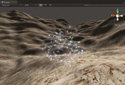
The types of natural effects that can be achieved with volumetric fog include low-lying clouds, mist, and dust as shown in Figure 7.36. You use it whenever you want to look at clouds from above or move through a variety of fog densities. Whereas the default fog gives a set density, in volumetric fog the player can walk through dense patches and then light patches.
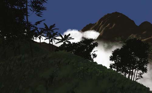
FIG 7.36 Volumetric clouds.
One method for producing volumetric clouds is to use mass instances of billboards with cloud textures on them. The system used to produce the image in Figure 7.36 was developed by Unity developer Julian Oliden and is available for download from http://jocyf.com/utilsEnglih.html. It is also included in the starter project file in the next workshop.
![]() Unity Hands On
Unity Hands On
Volumetric Clouds
Step 1.Download Chapter Seven/VolumeClouds.zip. Open the project in Unity.
Step 2.Locate the CloudsToy Mngr prefab in the Project under the Volumetric Clouds prefab.
Step 3.Drag and drop this prefab into the Scene. You won’t be able to see it yet as it requires a Terrain to align itself.
Step 4.Add a Terrain to the scene.
Step 5.Sculpt the terrain or import a height map. Paint the terrain as you like.
Step 6.Add a directional light.
Step 7.Select the CloudsToy Mngr in the Hierarchy. Press play. In the Scene you will be able to see the volume of the clouds over the terrain as shown in Figure 7.37. The CloudsToy Mngr sizes itself correctly to cover the terrain.
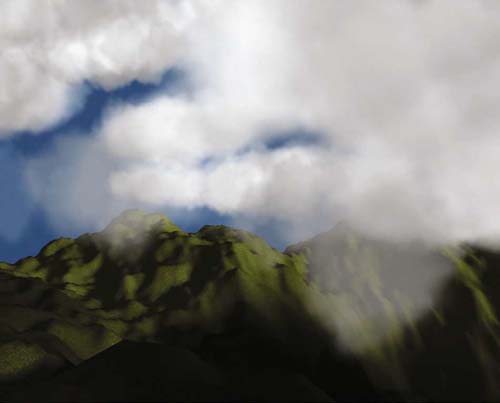
FIG 7.37 The Unity CloudsToy package in use.
Step 8.Add a first person controller to the Scene. Delete the original main camera.
Step 9.Play.
Step 10. If you have a mountainous terrain, you might like to lower the CloudsToy Mngr object such that it sits with the mountains poking out of the yellow bounding box in the Scene. This will create clouds that the player can walk through and above.
Settings for the CloudsToy Mngr can be changed through the Inspector by selecting the CloudsToy Mngr object in the Hierarchy. Settings begin with Cloud Presets, which allow you to select from Stormy-, Sunrise-, and Fantasy-looking clouds. These are useful to give you an idea of what the package can do as well as recovering to a more realistic-looking cloud type should you modify the other settings to the point of no return and end up with pinpoint clouds or no clouds at all.
Of particular note in the settings are the Cloud Creation Size and Disappear Multiplier. The Cloud Creation Size sets the size of the blue box displayed in the Scene. This box is the area in which clouds are spawned. The Disappear Multiplier determines the size of the yellow box. This is the area to which clouds will travel from the yellow box, but beyond they fade away.
Further down in the settings are cloud colors, sizes, and velocity.
The CloudsToy Mngr can be integrated into your own projects by importing the Chapter Seven/CloudsToy v1.2.unitypackage available from the Web site.
7.6 Weather
The weather affects the look and feel of our environment dramatically. Although players won’t be able to feel the cold of virtual snow in a game environment, the correct lighting, coloring, and special effects will make them feel like they are there and add an extra dimension to your scene.
7.6.1 Wind
Wind is one of these elements. Although you can’t see it, it moves environmental objects around. It looks especially good in a 3D world when acting on cloth, trees, and grass.
![]() Unity Specifics
Unity Specifics
Terrain Wind Element
A terrain in Unity can have wind applied through the setting of the bend factor of trees and using a wind zone. To do this, select a tree in the Terrain Editor and click on Edit Trees. In the pop-up window you will find a value for bend as shown in Figure 7.38. Set this to a value other than zero to make the trees sway in the breeze. Add a wind zone by selecting GameObject > Create Other > Wind Zone and then move the object near the First Person Controller. Play to see the trees move in the wind.
Grass and flower objects will sway automatically with the terrain breeze. The wind settings for this are found in the settings panel of the Terrain Editor as shown in Figure 7.39.
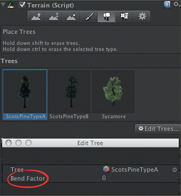
FIG 7.38 Adding a bend factor to terrain trees.
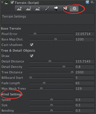
FIG 7.39 Setting the terrain wind.
Flying the Flag
In this workshop you will learn how to add wind effects with the Unity physics system.
Step 1. Create a new Unity Project. Add a cube and resize to the shape of a long flagpole.
Step 2. Add a Cloth by selecting GameObject > Create Other > Cloth. Rotate the cloth and resize to fit at the top of the flagpole. Add a texture to the cloth. One side of the cloth should be embedded in the flagpole cube as shown in Figure 7.40.
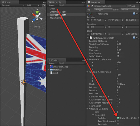
FIG 7.40 Creating a flagpole and flag.
Step 3. Select the Cloth in the Hierarchy and locate the Interactive Cloth component. Set the Size of the Attached Colliders to 1 and drag and drop the cube object (which is the flagpole) onto the Collider value (see Figure 7.40).
Step 4. Set the Interactive Cloth component’s value for External Acceleration and Random Acceleration to a vector parallel with the flag. In the given example, in Figure 7.40, this is (-10,0,0).
Step 5. Play. The flag will flap under the physics of its own weight and the acceleration values. While the external acceleration is constant, the random one will add extra boost now and then. This gives an effect similar to a real flag in a breeze.
Step 6. Beneath the flag add a plane to act as the ground.
Step 7. Next to the flagpole, above the ground, add a sphere. To the sphere add a rigidbody.
Step 8. Play. Ensure that the sphere falls to the ground.
Step 9. Select the sphere in the Hierarchy and select Component > Physics > Constant Force to add a force to the sphere. Set the value of Force for this to the same value as the Cloth’s External Acceleration, for example, (-10,0,0).
Step 10. Play. The sphere will now fall but in an arc. When it hits the ground it will roll off in the direction the constant force is pushing it.
Step 11. Create a new JavaScript file called windControls. Add the code in Listings 7.6.
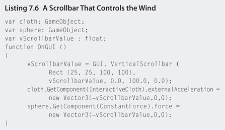
Step 12. Attach this code to the Main Camera. Select the Main Camera and locate the script in the Inspector. Set the values for cloth to the InteractiveCloth and sphere to the Sphere objects in the Hierarchy.
Step 13. Play. The scrollbar will control the amount of wind force on the objects.
7.6.2 Precipitation
Rain and snow add yet another dimension to the game environment. Not only do they look good but they add atmosphere and can be used to impair the vision of the player strategically. Precipitation falls into a category of computer graphics special effects called particle systems. They rightly deserve a category of their own and as such will be dealt with in the next section.
7.7 Particles
Particle systems are objects constructed from the mass generation of animated billboards. Each billboard represents a single particle. They are used most commonly in games to generate fluidic and fuzzy phenomena such as rain, snow, dust, fire, smoke, and explosions. The CloudsToy implemented previously and the Detonator objects used in other chapters’ workshops are examples of particle systems.
A particle system consists of an emitter that spawns the particles at a specific location. As they are created, each particle is given a velocity, size, and life length. The particle begins its life, is scaled to the given size, and travels off at the set velocity for the length of its life. At the end of its life the particle is destroyed. For extra effect, a particle can be given a rotational velocity, an animated color change, and size changes throughout its life. Several example particle systems are illustrated in Figure 7.41.
FIG 7.41 Particle systems: (a) a uniform system with all particles having a vertical velocity; (b) a vertical system with random x and y velocities, expanding size and changing color; (c) a fire made with three systems-one for inner glow, one for flames, and one for smoke; and (d) a water fountain.

Particle systems can be very processor intensive as they can require hundreds or thousands of particles to simulate the desired effect. However, having each particle represented as a 2D billboard helps lower overheads (somewhat).
A number of prefab particle systems are included in Unity packages; however, the best way to get an understanding of their intricacies is to create them from scratch.
![]() Unity Hands On
Unity Hands On
A Snowy Retreat
Step 1. Download Chapter Seven/Particles.zip. Open the SnowyRetreat scene in Unity.
Step 2. Select GameObject > Create Object > Particle System to add a particle system into the scene. While selected, the particle system runs even if the game is not. The default particle system is shown in Figure 7.42.
FIG 7.42 Unity’s default particle system.
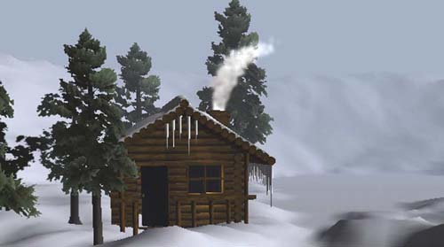
Step 3. Rename the particle system Smoke and reposition it in the top of the chimney of the log cabin.
Step 4. Select Smoke in the Hierarchy and locate the Ellipsoid Particle Emitter component in the inspector. This is the object spawning the particles.
Step 5. Set the World Velocity y value to 2. Note how the particles start to move upward.
Step 6. Change the Min Size to 3 and the Max Size to 4. This is the range of sizes between which particles will be scaled.
Step 7. Modify the Min Energy to 5 and the Max Energy to 15. This is the range of lifetime given to individual particles. Note how the particles go farther up. This is because they are living longer than before.
Step 8. Change the x and z values for Rnd Velocity to 0.5. This will give each particle a random x and z value added on top of any world or local velocity. In this case it will make the particles go up and slightly out.
Step 9. Below in the Particle Animator component set the x value for force to 0.5. This will apply a constant force in the x direction to each particle. It will cause them to rise up out of the chimney and start to move off at an angle as if blown by a slight wind.
Step 10. Set the Rnd Force’s x and y values to 1. This will add an extra force to the particles between -0.5 and 0.5 in the x and y directions. In some cases it will add to the constant force and other times counteract it. This will make for more random smoke movement while still keeping it blowing away into the distance.
Step 11. Change the Animate Colors to alternate colors of white and gray. This will give the smoke more character and depth. These colors are the colors the particle will cycle through during its lifetime, starting at color 0 and finishing at color 4.
Step 12. Play. By now you should have a nice smoking particle effect coming from the chimney as shown in Figure 7.43.
Step 13. Next we are going to make it snow. Add a new particle system to the scene and call it Snow. Position it above the cabin.
Step 14. Set the World Velocity y value to -5. This will make the particles fall.
Step 15. Change the Min and Max Energy to 20 and 50, respectively. The particles need enough time to fall to the ground before being destroyed.
Step 16. Increase the Min and Max Emission to 200 and 500, respectively, to create more particles. For denser snow you can increase these values later.
Step 17. Set the Particle Emitter’s Ellipsoid size to (50,1,50). This will increase the area in which particles are created in the x and z directions, meaning that they will be created at the same y position but cover a larger area. By now the particles should be looking like snow.
FIG 7.43 A particle system simulating chimney smoke.
Step 18. If you’d rather have bigger snowflakes, increase the Min and Max Sizes of the particles.
Step 19. Add the First Person Controller to the Scene and place it just outside the cabin. It may need to be resized to fit the scene.
Step 20. Delete the old Main Camera.
Step 21. Select the First Person Controller camera and set the Background color to that of the fog.
Step 22. Play. Watch the snow falling.
The only problem with the current snow is that it is a very isolated system. If you walk your character down the road a little, you will walk out of the snow zone. You could increase the size of the emitter ellipsoid to cover a larger area, but this would mean increasing the number of falling particles to get the same density. Unfortunately, the more particles, the more strain on the processing of your game and the slower it will run. However, we can employ a simple trick to make it look as though it is snowing everywhere on the terrain.
Step 23. Select the Snow in the Hierarchy and drag and drop it onto the First Person Controller to attach. Now it will move everywhere the player does. Select the Snow object once attached and set its position to (0,10,0). This will ensure that the snow emitter is always directly above the player.
Step 24. Depending on how fast the player can move, you may need to increase the ellipsoid size a little so that the player never outruns new particles. In this example, if you set the ellipsoid’s size to (100,1,100) and the Min and Max Emissions to 500 and 100, respectively, it gives good snow coverage that can keep up with the player’s maximum speed.
Step 25. Finally, we are going to add little snow splats on the ground when the snowflakes hit the ground. Create a new particle system and call it Splat.
Step 26. Set the Min and Max Sizes to 0.1 and 0.3, the Min and Max Energies to 0.3 and 0.3, the Min and Max Emissions to 10 and 10, the World Velocity y value to 1, the Rnd Velocity to (1,1,1), and the Ellipsoid to (0,0,0). Tick the One Shot box.
The emitter ellipsoid size of 0 will cause all particles to originate from the same location, and One Shot will make the emitter shoot out all particles at once instead of releasing them randomly. This creates a little puff effect.
Step 27. Create a new prefab from the Splat and remove the Splat object from the Hierarchy.
Step 28. Select the Snow particle system attached to the First Person Controller in the Hierarchy. From the main menu select Component > Particles > World Particle Collider. At this instance you will notice a change in the behavior of the snow. It will start to bounce off everything!
Step 29. Create a JavaScript file called particlehit and add the code in Listings 7.7.
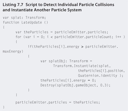
Because individual particles do not exist to attach script to, this code attaches to the particle emitter and loops through all its particles. When it detects a particle’s individual energy value has become larger than the emitter’s maximum energy setting, it instantiates a splat. The trick now is to cause the particle’s energy to spike when it collides as this doesn’t happen automatically.
Step 31. Select the Snow object and locate the World Particle Collider component in the Inspector. Set the Collision Energy Loss to -100. This will boost the energy (a.k.a. life) of the particle by 100, which is far greater than the emitter maximum of 50. When this happens, the attached particle script test will become true and a splat obj will be instantiated.
Step 32. Before playing, set the Splat value of the Particle Hit script attached to the Snow to the Splat prefab created before. This is illustrated in Figure 7.44.
Step 33. Play. The snowflakes will now create small puffs when they hit the ground. The final scene is shown in Figure 7.45.
The very same particle system can be used to create rain. The only difference would be the size of the particles and the splashes.
FIG 7.44 Setting the snow particle system up to detect particle collisions and create a splat.
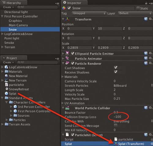
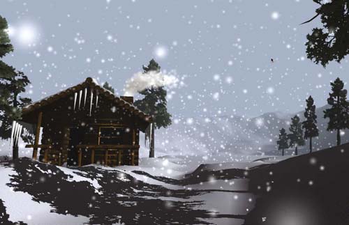
FIG 7.45 The final snow scene.
7.8 Summary
This chapter examined the artistic and scientific aspects of the real world in order to recreate similar environments as game environments. So many of the physics and mathematics of the real world translate into virtual environments, and an understanding of these assists us in making the virtual look and feel as real as possible for a player.
Only through observing the world around us, the types of vegetation, the shapes of rocks, the colors in the sky, and the way things move can we gain a deeper appreciation of the articulation of what can turn a virtual environment into something believable. This chapter has only scratched at the surface of what is possible in developing the aesthetics of a game environment, although it is hoped that you've gained enough knowledge and confidence to go in search of new techniques that you can incorporate in your games to make them look that much more professional and polished.
1 We need to add an extra vertex along the sides so that there is an odd number of vertices, allowing for an exact middle one to be located.
2 Slightly modified by the author to suit the purposes of the workshop.