Lesson 27. Taking Apart a MacBook Pro
Reference Files
MacBook Pro service manual (macbook-pro.pdf)
Removing a stuck disk from an optical drive (macbook_stuckdisc.pdf)
Handling slot-load optical drives (070_2195B_draft.pdf)
Time
This lesson takes approximately 2 hours to complete.
Goals
Remove a logic board from a MacBook Pro
In the previous lesson, you learned how to install memory in a MacBook Pro. Now you’re going to become even more familiar with the MacBook Pro, taking apart all of the components necessary to remove a faulty logic board, one of several possible causes of a no video symptom that we will cover in Lesson 28, “Troubleshooting a MacBook Pro.”
In the interest of conserving space, reassembly instructions are not reproduced on these pages but are included in the service manual on this book’s companion website, www.peachpit.com/ats.deskport3.
Further, this lesson is meant to accompany the Apple Service Source manual, also provided on the website. If you are an Apple Authorized Service Provider (AASP), practice the Take Apart and reassembly at your own speed until you feel confident that you can replace any MacBook component to factory specifications. AASPs should download and refer to the latest service manual before servicing any Apple product. Non-AASPs should read the service manual and this text to become familiar with the procedures.
Note
If anyone other than an AASP opens a MacBook for any reason, and any damage to the unit results, the repair of such damage will not be covered under the Apple warranty or the AppleCare Protection Plan.
Required Tools and Equipment
In addition to the standard electrostatic discharge (ESD) wrist strap and mat—which you should always use, following the guidelines discussed in Lesson 4, “Safe Working Procedures and General Maintenance”—you will need the following tools and equipment:
• Soft cloth and clean, non-marring work surface
• Multi-compartment screw tray (such as a plastic ice cube tray)
• Nylon probe tool (also called a Black Stick) or other non-conductive plastic flat-blade probe tool
• Phillips #0 screwdriver (magnetized)
• Torx T6 screwdriver (magnetized)
• Razor knife
• Needle-point metal probe
• Kapton tape (0.5-inch x 12-yard roll)
• Thermal grease
• Gasket kit
• Alcohol pads
• Apple Hardware Test (AHT) diagnostic disc for the MacBook Pro model
Taking Apart the MacBook Pro
At each stage of the Take Apart procedure, we’ll let you know if there are special notes and information; otherwise, we proceed from component to component, from the outside in.
Proceed to page 99 of the service manual to review the preliminary steps for the logic board replacement. Use the service manual as your main guide and this text to accompany it.
Servicing a MacBook Pro requires a light touch, since it is comprised of many small, expensive components arranged in a compact form factor. Always exercise care, and do not exert too much pressure when disassembling a MacBook Pro.
Battery
Proceed to page 19 in the service manual to review the battery removal procedure. You should be familiar with this procedure from the preceding lesson. Whenever you open any portable computer—whether to install memory or remove a faulty component—your first step is to shut down the computer and remove the battery.
- Perform step 1 on page 20 of the service manual to shut down the computer and wait 30 minutes to allow for cooling before continuing.
Warning
Always shut down the computer before opening it to avoid damaging its internal components or causing injury. After you shut down the computer, the internal components can be very hot. Let the computer cool down before continuing.
- Perform step 2 on page 20 to disconnect the power cord and any other cables connected to the computer.
- Complete steps 3 and 4 on page 20 to place the computer face down and to perform the steps to lift the battery out of the battery bay, reading all notes that apply to these steps. Remember that removing the battery will prevent you from turning on the computer accidentally.
Memory
The memory door must be removed so that the top case can be removed. Proceed to page 21 of the service manual to review the memory module removal procedure.
- Perform steps 1 through 3 on page 22 of the service manual to remove the three screws from the memory door, and set the door aside.
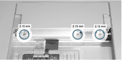
Three 2.15-mm screws
- Perform steps 4 and 5 on page 23 to remove the installed memory modules.
Top Case
The metal top case and attached keyboard assembly must be removed to access various internal components, including the hard drive. For this procedure, we will be removing the top case only.
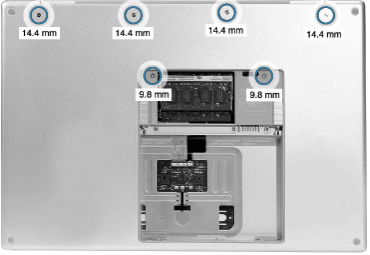
- Perform steps 1 and 2 on page 28 of the service manual to place the computer upside down and remove the six screws, as shown on the following page.
Four 14.4-mm screws are at top and two 9.8-mm screws are in center.
- Perform step 3 on page 28 to rotate the computer and remove the two screws along the front of the battery bay.
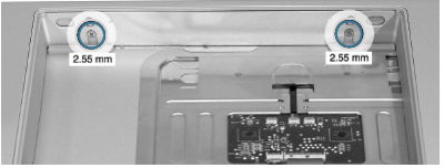
Two 2.55-mm screws are at top.
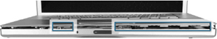
- Perform step 4 on page 29 to remove the eight 3.4-mm screws from each side of the computer.
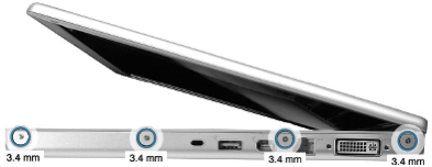
Four 3.4-mm screws must be removed from each side of the computer.
- Complete step 5 on page 29 to remove two 3.2-mm screws from the back edge of the computer.
- Complete steps 6 and 7 on page 30 to face the computer forward and loosen the top case along the rear of the left and right sides.
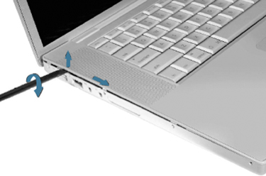
Gently loosen both rear sides of the top case.
- Perform step 8 on page 31 to slowly encourage the snaps and screw tabs to release as you move right. Pay attention to the note for this step. A snapping noise as the snaps release is normal.
Warning
To preserve the delicate bead trim around the top case, try using your fingernails to gently loosen and pull up on the top case before using a nylon probe tool.
The tabs have released, but the top case is still connected to the bottom case.
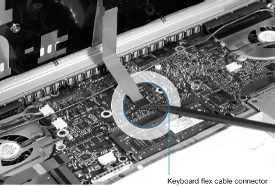
- Perform step 9 on page 32 to disconnect the keyboard flex cable from the logic board.
Right Ambient Sensor Lens
The right ambient sensor lens is actually part of the logic board. You will need to remove its dust cover. Proceed to page 83 in the service manual and perform steps 1 and 2 to carefully remove the right sensor’s dust cover.
Right Speaker
Turn to page 94 in the service manual to review the right speaker removal procedure.
- Perform step 1 on page 94 to remove the low voltage differential signaling (LVDS) grounding strap screw.
- Once you have accessed the tape along the right side of the speaker, perform step 2 to pry up the tape with a nylon probe tool and allow the speaker to rotate.
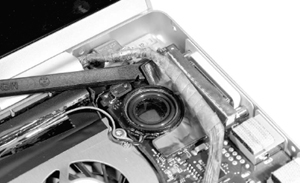
Carefully use the tool to pry the tape.
- Complete the speaker removal by performing steps 3 and 4 on page 95 to lift out the speaker and disconnect the thermal sensor, if required.
Fans
Turn to page 86 of the service manual to review the fan removal procedure. Pay particular attention to any notes.
- Perform steps 1 and 2 on page 87 to remove the right fan.
Warning
Be very careful in using a razor knife to cut the Kapton tape. A small slip of your hand could seriously damage the logic board.
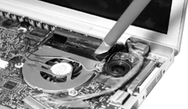
- Perform step 1 on page 88 to disconnect the ambient light sensor flex cable from the logic board.
The tight sensor flex cable connector is very fragile.
- Perform steps 2 and 3 on page 89 to peel the flex cable from the fan cover, and then disconnect and move cables out of the way.
- Perform steps 4 and 5 on page 90 to cut the Kapton tape from the fan and remove the three screws that hold the fan in place.
- Complete step 6 on page 91 to remove the left fan from under the left speaker screw tab.
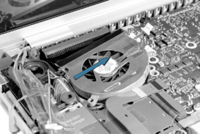
Remove the left fan in the direction indicated by the arrow.
Optical Drive
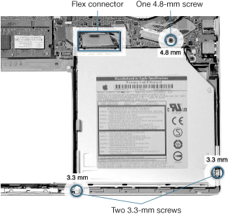
Turn to page 75 in the service manual and review the optical drive removal procedures.
- Perform step 1 on page 76 of the service manual to disconnect the flex connector.
- Complete the removal of the optical drive by performing step 2.
Logic Board
Review the logic board procedures in full starting on page 99 of the service manual. Pay attention to notes and warnings.
- Perform 1 step in the procedure on page 100 to disconnect cables from the logic board.
- Perform step 2 on page 101 to tape the sensor cable to the display assembly.
- Complete step 3 on page 101 to remove 10 screws that hold the logic board in place as pictured below.
Note the location of the one screw that is shorter than the rest. Be sure to keep track of screw placement.
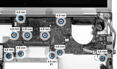
Nine 4.8-mm screws and one 4.5-mm screw on the logic board
- Read step 4 on page 102 of the service manual. This step is extremely important.
- Ensure that you have indeed removed all of the logic board screws, then perform step 5 to slowly begin to lift the logic board.
- Without removing the logic board completely, perform step 6 on page 102 to remove the connector from under the board.
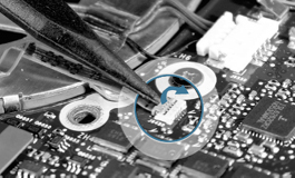
- Perform steps 7 and 8 on page 102 to carefully lift the left side of the board to disconnect the thermal sensor cable.
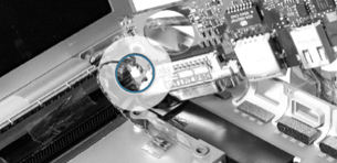
Thermal sensor cable (circled in blue)
- Review the warning note on page 103 and perform step 9 to remove the logic board. Set aside the logic board in an antistatic bag.
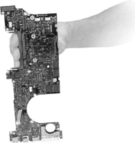
Logic board
The logic board replacement procedures are provided in the service manual beginning on page 104. Please review all steps in full before performing any procedures. Installation of EMI gaskets and new thermal grease is crucial to the proper operation of the unit.
When You Are Finished
- Return the faulty logic board to Apple in the packaging provided.
- Install the replacement logic board following the instructions in the service manual.
- Verify that the system works correctly by starting up the system and running AHT, Apple System Profiler, and some common Apple applications that test the system’s capabilities, including sound, display, and hard drive functions.
Lesson Summary
• Whenever you work on the internal components of any computer, it is imperative that you follow proper ESD procedures and follow steps in the service manual in the order provided.
• Each product has different Take Apart procedures that are explained in detail in its particular service manual. The information presented in this lesson applies to the MacBook Pro.
• Gaining access to a particular component often requires the removal of several other components first. Each component must be properly protected from damage as it is removed.
• You must unplug the power adapter and remove the battery to prevent the MacBook Pro from turning on during the Take Apart procedure.
• Some parts—such as thermal grease—must be replaced, not reused, when you reassemble the computer.
• Take precautions with fragile internal components to protect them from ESD and surface damage. Screws and other small objects can fall into the computer, shorting the components upon startup.
• Always exercise care and do not exert too much pressure when disassembling the MacBook Pro, as internal components are fragile.
• When taking apart components, pay particular attention to the routing of cables and connectors. Reassembly requires these to be in the correct place.
• Some connectors are very fragile and require special precautions.