
5. Image Rendering
One of the key elements of Sir Lamorak’s Quest—and, in fact, all games, unless you’re thinking about the old text-based adventures—is the ability to render images (sprites) to the screen. Without graphics, the game would be pretty dull.
In this chapter, we run through the key concepts needed to render images to the screen using OpenGL ES. We cover the basics of rendering triangles, texture mapping, loading textures from image files, and improving performance.
We won’t cover all aspects of these items (doing so would require a book about double the size of the one you hold in your hands), but we cover enough so you understand how to use OpenGL ES within the following classes:
• Image
• Texture2D
• TextureManager
• ImageRenderManager
Together, these classes enable us to render any image we want to the screen quickly, both in terms of the code needed within the game as well as the game’s performance.
Introduction to Rendering
A good place for us to start this chapter is looking at how we render something to the screen using OpenGL ES. If you tried the example at the end of the last chapter, you saw how a square and a triangle are configured and rendered to the screen.
The first point to note is that with OpenGL ES, there is no concept of a quad (that is, a primitive shape that can be defined using four vertices). Although quads are supported in OpenGL, OpenGL ES can only render shapes using triangles to the screen.
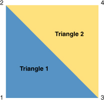
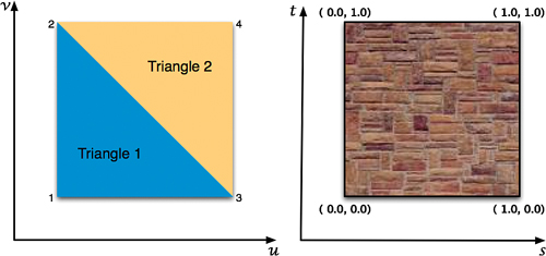
Although you may think this is a limitation, it really isn’t. Every imaginable shape can be rendered to the screen by joining triangles together. Computer animation has been doing it this way for years. For example, you can render a quad using two triangles, as shown in Figure 5.1.
Figure 5.1 Creating a quad using the GL_TRIANGLE_STRIP mode.
For Sir Lamorak’s Quest, we will be rendering a lot of images on the screen, including the following:
• The player/character, Sir Lamorak himself.
• The baddies (that is, ghosts, monsters, a bat, and so on)
• Doors
• Tiles for the tile map
• Letters for fonts
Each of these items requires us to define a quad and then fill it with the necessary image (texture). We cover how to map a texture to a quad (or any shape, for that matter) later. For now, let’s focus on how to define and render a quad.
Rendering a Quad
To render a quad, you need to define two triangles and then “stick” them together. If you tried the exercise at the end of Chapter 4, “The Game Loop,” you may have spotted the hint I gave you. This hint suggested you try using a different drawing mode when asking OpenGL ES to render the contents of the vertices array we had set up. In Chapter 4, we used the glDrawArrays command and one of the following modes:
• GL_TRIANGLES
• GL_TRIANGLE_STRIP
These are not the only modes available to use, however. You can also use the following:
• GL_POINTS
• GL_LINE_STRIP
• GL_LINE_LOOP
• GL_TRIANGLE_FAN
For our needs, we’ll work with GL_TRIANGLES and GL_TRIANGLE_STRIP.
The difference between these is in how OpenGL ES uses the vertices we provide and how many vertices we actually need. We used the following command in Chapter 4’s example to render our quad (square):
glDrawArrays(GL_TRIANGLE_STRIP, 0, 4);
The first parameter defines the mode we want to use when rendering, and is set to GL_TRIANGLE_STRIP. The second parameter defines the stride, 0 (which we cover later), and the third parameter, 4, defines how many vertices we wanted OpenGL ES to render.
So, what does using the GL_TRIANGLE_STRIP mode tell OpenGL ES to do? The clue is in the name. OpenGL ES creates a strip of triangles using the last two vertices from the previous triangle, plus an additional vertex to create a new triangle. This new triangle shares two of its vertices with the previously defined triangle. As you can see in Figure 5.1, a triangle will be drawn using vertices 1, 2, and 3 when OpenGL ES renders the vertices, and a second triangle will be drawn using vertices 3, 2, and 4.
It is also possible to turn the square into a house, giving the square a pointed roof by using just one more vertex; GL_TRIANGLE_STRIP makes this very simple. To create the triangle for the roof, simply add one more vertex to the four we have already defined. OpenGL ES then joins that vertex to the previous two to form another triangle. Figure 5.2 shows you the result of adding this extra vertex.
Figure 5.2 This house was created by adding a fifth vertex.
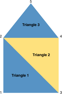
Here, we’ve created three triangles using only five vertices. The triangles shown in Figure 5.2 are defined using the following vertices:
![]()
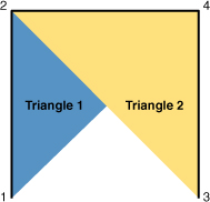
The order in which the vertices are passed to OpenGL ES when using GL_TRIANGLE_STRIP is important so that it renders the triangles you are expecting. For example, if you provided the vertices in a different order than the preceding—say 1, 2, 4, and 3—you would get the result shown in Figure 5.3.
Tip
Having the vertices out of order is a common problem and certainly something I had to sort out a number of times. If you see an image such as that shown in Figure 5.3, there’s a good chance that your vertices aren’t in the correct order. The order of vertices should be kept the same to reduce confusion and rendering issues that are hard to trace.
Figure 5.3 Result of using vertices in the order 1, 2, 4, and 3.
When using GL_TRIANGLES, OpenGL ES renders a single triangle for each set of three vertices in the array. To create the same quad shown in Figure 5.1, the vertices defined within the vertices array passed to OpenGL ES would need to be 1, 2, 3, 3, 2, 4. When using GL_TRIANGLES, you need to define each triangle with all three of its vertices. If you don’t, GL_TRIANGLES won’t link from one triangle to the next, as is done when using GL_TRIANGLE_STRIP.
It is important that you understand the difference between these two modes. If you need to render a number of triangles that are all linked together, use GL_TRIANGLE_STRIP. However, if you want to render a bunch of triangles that aren’t linked and are randomly placed, GL_TRIANGLES is the mode to use.
Note
Although I have said that you can use GL_TRIANGLES to render triangles in different locations that are not linked, it is actually possible to achieve the same result using a GL_TRIANGLE_STRIP. If you define degenerate (zero-area) triangles in your vertex array, you can instruct OpenGL ES to move to a new vertex location without actually rendering the degenerate triangle. This enables you to introduce discontinuities, or “jumps,” in the strip. GL_TRIANGLE_STRIP can also improve performance when rendering complex meshes (shapes).
Notice that you need four vertices to render a quad using GL_TRIANGLE_STRIP but six vertices to render a quad when using GL_TRIANGLES. If you were rendering only a single quad at a time, it would make sense to use GL_TRIANGLE_STRIP because it reduces the number of vertices you need. There are, however, reasons why you don’t want to draw every item on the screen using separate OpenGL calls to glDrawArrays. We cover those reasons later in this chapter.
Texture Mapping
Texture mapping is the process of applying an image (texture) to a primitive (for example, a point, line, or polygon). This technique is useful because it enables you to add more realism to a scene than using primitives alone. For example, if you wanted to render a wall made of stone, you could render each stone on its own, providing all the vertices needed to define the points for each stone, and then color the stone as necessary.
This would work but would be very hard to manage and could easily cause performance problems given the number of polygons required. An easier approach is to define a polygon that is the size of your wall and then fill it with an image of a real stone wall. This will look much more realistic and gives you the effect you need with a single polygon rather than thousands.
The basic concept of texture mapping is that for each vertex defining a point in a polygon, you also provide a vertex to a point in a texture. You then supply this information to OpenGL ES, which renders the texture inside the polygon while performing all the complicated work involved to make the texture fit.
Texture Coordinates
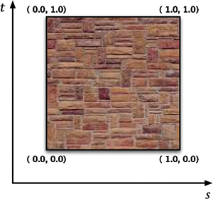
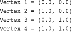
Texture coordinates are used to define a location inside a texture. The vertices that define a polygon can (in theory) be any number you want within an OpenGL ES 3D space. The coordinates that define a texture are constrained by default, though, from 0 to 1 along both the t and s axis, as shown in Figure 5.4.
The same coordinate system is used no matter how big or small the size of the texture (that is, the maximum width or height of a texture is specified as 1.0, regardless of the actual texture size). If you go beyond 1.0, the results depend on how you have configured parameters for clamping and tiling.
Figure 5.4 Texture coordinates and axis names.
Although the axis used when defining a polygon is normally called (x, y), it is common for the same axis when defining texture coordinates to be referred to as (s, t), as shown in Figure 5.4. Just to make things even more confusing, it is also common to see the polygon axis referred to as (u, v) rather than (x, y). This leads to the term UV mapping, which is used in many 3D applications (that is, the mapping of the (s, t) coordinates onto the (u, v) coordinates).
Figure 5.5 shows how we can map the texture coordinates to the polygon coordinates.
In looking at Figure 5.5, you can see that the following mapping coordinates are used to map the full texture to the polygon vertices:
Figure 5.5 Polygon and texture coordinates.
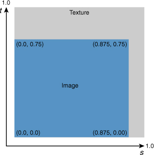
If you just wanted to map a portion of the full texture to the polygon, we can adjust the texture coordinates as necessary. Figure 5.6 shows the texture coordinates for mapping just a quarter of the texture to the polygon.
Figure 5.6 Texture coordinates defining one quarter of the texture.
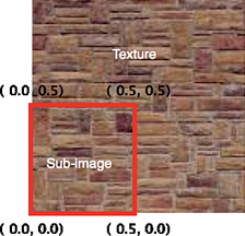
This time, the mapping from the polygon vertices to the texture coordinates would be as follows:
If the polygon dimensions are larger or smaller than the texture defined by the texture coordinates, the texture is scaled up or down by OpenGL ES to fit the polygon dimensions. This is a useful technique for scaling images. By simply changing the dimensions of the polygon but keeping the mapping between the polygon vertices and the texture coordinates the same, the image can be scaled up or down as necessary. Two parameters control how OpenGL ES handles scaling:
![]()
We show you how to use these parameters later in this chapter.
Now that we have covered the basics on texture coordinates and how they can be mapped to polygon coordinates, we can move onto looking at the code we need to create a texture, load image data associated with that texture, and render that texture to the screen.
Interleaved Vertex Arrays
Before we push into the ImageRenderManager class, it’s worth discussing Interleaved Vertex Arrays (IVA), which are used in the ImageRenderManager.
We have seen the term vertex array already, but we have not talked about it in much detail. From the code we have already seen, you may remember that we have been using vertex arrays to define the vertex data we have been passing to OpenGL ES:
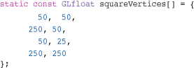
This code shows how to define the square’s vertices used in the CH04_SLQTSOR project in Chapter 4. This is known as a vertex array. At the moment, it contains nothing but vertex information for the square’s geometry. We also define an array to store color information in CH04_SLQTSOR. This array contained the definition of a color for each vertex in the squareVertices array.
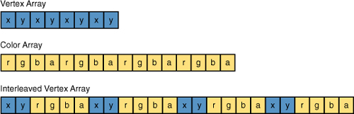
With an IVA, you create a single array that contains all the information in one contiguous block (for example, vertex and color), as illustrated in Figure 5.7. There is also other data that is also normally stored in arrays and passed to OpenGL ES, such as texture coordinates.
Figure 5.7 shows individual vertex and color arrays that have then been merged into a single IVA. Reducing the number of arrays that we need to pass to OpenGL ES improves performance; this is key to what ImageRenderManager was designed for.
Figure 5.7 Interleaved Vertex Array containing geometry and color information.
When telling OpenGL ES about which vertex array to use when rendering, we have been using glVertexPointer and glColorPointer, as shown here:
![]()
Although the commands are different, the parameters they take and their meaning are very similar. When using glColorPointer, the first parameter defines the number of components per color. Under OpenGL ES, this parameter must be 4, as a color is made up of red, green, blue, and alpha. When using glVertexPointer or glTexCoordPointer, the first parameter defines the number of coordinates per vertex.
The third parameter is the stride, which specifies the number of bytes between consecutive vertices or colors. Until now, we have been using 0 for this value, which means that the color and vertices arrays have been tightly packed. In a vertex array, one vertex pair follows immediately after the previous vertex pair, as can be seen in the vertex and color arrays in Figure 5.7.
When using IVAs, we need to set the stride to the distance in bytes between the start of one vertex pair and the start of the next vertex pair. Using the IVA in Figure 5.8 as an example, the glVertexPointer stride would need to be 24 and the glColorPointer stride would also need to be 24.
Figure 5.8 Color and vertex stride.
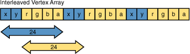
In case you’re wondering how those figures were calculated, the answer is that vertices are stored using two GLFloats, each of which requires 4 bytes of storage. Because we need to advance six elements within the IVA (x, y, r, g, b, a) to reach the next vertex pair, simply multiply 4 (the size of the float) by 6 (the number of elements in the IVA). This gives you 24, the number of bytes OpenGL ES needs to advance to find the next vertex pair. The same applies to the glColorPointer.
You may have to read through that again to clearly understand what is being done, but once you understand the concept of stride, it will become much easier.
In this example, we calculated the number of bytes manually; however, you will be pleased to know that it is possible to have the compiler calculate this value for you by using the sizeof statement. If you have not seen the sizeof statement before, it returns the number of bytes needed to store the type that has been passed to it. We could have used the following instead:
![]()
Note
This example uses the &iva array to specify the start element in the array along with the structure element (for example, geometryVertex). This tells OpenGL ES where to get the necessary data from within the array.
This would have given OpenGL ES the same numbers we calculated manually, and you would not have had to worry about how much storage a GLFloat actually needs.
Even with this approach, we still had to specify how many elements we needed to stride over. To make things even easier, we could have used a structure to store the vertex and color information and simply retrieved the size of that structure or element within the structure. We are going to cover structures next.
Structures
Now that we have seen what an IVA looks like, how do we actually create one? For this, we need to use structures. A structure is a collection of variables grouped together under a single name. The variables can be of different types, and each has a unique name used to identify it within the structure. What is also handy is that a structure can be embedded within a structure, which is perfect for our needs.
We need a number of structures in which to store our image data. You will find the structures we are going to run through inside the CH05_SLQTSOR project. In this project is a group called Global Headers, inside which you’ll find the Structures.h header file. If you open this file, you see all the structures that are needed by the ImageRenderManager and Image classes.
When rendering images in Sir Lamorak’s Quest, we need to define the quad in which the image will be rendered, the texture coordinates, and a color that we can use to apply transparency or a color filter to our image. Because each vertex of the quad will be made up of three pieces of information—namely, vertices, texture coordinates, and color—it makes sense to use a structure that stores this information. The Color4f structure will be covered later in the chapter when we examine the Image class.
The structure we are going to use is called TexturedColoredVertex, as shown in Listing 5.1. This structure has two other structures within it: CGPoint and Color4f. CGPoint is itself a structure included within the Core Graphics API. If you wanted to make sure your game engine was portable, it would be a good idea to actually create your own structure to store points rather than using a structure that is specific to the iPhone. The second structure is Color4f which we will cover later in this chapter.
Listing 5.1 The TexturedColoredVertex Structure

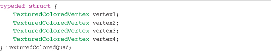
Having a vertex on its own is not much use unless you are rendering points, so we need a structure that enables us to define a quad (that is, four TexturedColoredVertex structures). This structure, TexturedColoredQuad, is shown in Listing 5.2.
Listing 5.2 The TexturedColoredQuad Structure
The final structure needed to support the rendering manager and Image class is the ImageDetails structure, shown in Listing 5.3.
Listing 5.3 The ImageDetails Structure
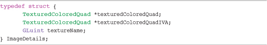
The structure shown in Listing 5.3 stores information about the image’s quad, texture coordinates, and color. The structure also stores the OpenGL ES texture name used by the image, and where inside the ImageRenderManager IVA texturedColoredQuadIVA is held.
Image Rendering Classes
Inside the Chapter 5 example project (CH05_SLQTSOR), you see a new group called Game Engine. This is where the core classes for the game are stored. This group also contains two additional groups: Image and Managers.
Inside the Image group, you find the Image class files and a further group called Texture2D that contains the Texture2D class. The Texture2D class is responsible for actually creating an OpenGL ES texture and associating it with image data loaded from an image file. The Image class is used to wrap instances of the Texture2D class, providing a simple API allowing us to rotate, scale, translate, and render the texture to the screen.
Inside the Managers group, you see two further groups called Texture Manager and Image Render Manager.
Inside the Texture Manager group is the TextureManager class. This class enables us to cache textures that have been created and share them between Image class instances.
Inside the Image Render Manager group is the ImageRenderManager class. This class is responsible for batching up images that need to be rendered and then rendering them using the least number of OpenGL ES API calls necessary. This is important so that we can reduce the number of OpenGL ES API calls when rendering a large number of images to the screen.
We now run through the steps needed to create and render an image to the screen and, at the same time, take a look at the classes we use in Sir Lamorak’s Quest to carry out these functions.
Although the steps needed to actually create and render an image to the screen are not complex and can be achieved in just a few lines of code, we need something slightly more complex. This extra complexity is required to manage our resources more efficiently and maintain performance when we have a large number of images to render.
Note
From this project onward, the Common.h file has been renamed to Global.h in the Global Headers group.
Texture2D Class
As described earlier, the actual loading of image data and generation of an OpenGL ES texture is performed within the Texture2D class. By now, you should be getting the idea of how the class header files are created and used, so I won’t run through the headers of the class files we are going to be looking at, unless there is something specific I want to point out.
Now, open the Texture2D.m file, and let’s run through the functions it performs.
Initialization
The Texture2D class does not actually provide any functionality outside of its initialization. After the object has been initialized with an image, its only job is to store information about the OpenGL ES texture that was generated from the image data. Other classes such as the Image class then use this information. For this reason, initWithImage:filter: is the only method in this class.
Loading the Image
To create a texture in OpenGL ES, we need to have some image data that is going to be used for our texture. Texture2D uses the UIImage class to load an image and then extract the image data needed by OpenGL ES. This is useful because UIImage is able to load a variety of different image formats, such as PNG, BMP, GIF, and so on.
If you look inside the initWithImage method inside Texture2D, you see that a UIImage instance is passed in from which the underlying bitmap image data is referenced:
![]()
CGImage gives us the underlying bitmap image data that has been loaded by UIImage, and we are placing it inside a CGImageRef structure. This enables us to read data from that structure when we look for the image format, size, and so forth.
The class then checks to make sure that image data has been found. If not, an error is raised.
Using image, we can now retrieve information about the image’s alpha and color space. Because we now have access to the CGImage information using CGImageRef, we can easily get to the information we need using the following commands:
![]()
With this information, we are able to detect if the image has an alpha component and its color space. We will need this later when getting the image data ready for OpenGL ES.
Sizing the Image
Let’s run over a couple of important points about OpenGL ES textures.
The first is that the size of all textures in OpenGL ES has to be power-of-two. This means that your image needs to have a width and height equal to one of the following values:
![]()
The width and height don’t need to be the same (that is, 128×128), as you could have a texture that is 512×64, but they do need to use a value from the previous list.
The second point is the reason why I stopped listing numbers at 1024. The largest single texture that can be loaded into OpenGL ES on the iPhone is 1024×1024 pixels. If you need to display a larger image, you would need to chop it up into separate images, each no larger than 1024×1024. Using smaller images to create much larger images is a common trick used in game development, and we will be covering this when we look at tile maps in Chapter 9, “Tile Maps.”
Note
The iPhone 3GS, iPhone 4 and iPad support texture sizes of 2048×2048.
Now that we have captured information about the image that has been loaded, we need to make sure that the size of the image is both a power-of-two and not above 1024. You could just make sure that all images you create are already the right size before you use them, but that can become a pain, and you may have images that cannot have a size that is power-of-two.
To make things easy, Texture2D is going to handle the sizing for us. All we need to do is get the current size of the image we have loaded and then check to make sure that the dimensions are both power-of-two and no larger than the 1024×1024 limit.
Getting the content size is easy enough, as follows:
![]()
Having obtained the image size, we now need to make sure that it’s power-of-two. There is no magic in this—just a couple of loops for width and height. The loops to calculate the width and height of the image, making sure they are a power-of-two, is shown in Listing 5.4.
Listing 5.4 Setting the Image Size in Texture2D to a Power-of-Two
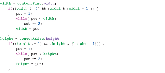
If the width of the image is greater than 1 and it’s not already a power-of-two, we start at 1 and keep multiplying by 2 until the new width is greater than the current width. This gives us a width that encompasses the image and is power-of-two. We then do the same for the height. The width and height variables are used when creating the OpenGL ES texture and will not affect the actual image we have loaded.
Having calculated the dimensions of the image to be power-of-two, we need to make sure that it does not exceed the maximum texture size.
For this, we use Core Graphics functions and create a CGAffineTransform loading in the identity matrix. The identify matrix we are loading in performs the same function in Core Graphics as the identify matrix we covered back in Chapter 3, “The Journey Begins:”
![]()
Having loaded this matrix, we check to see if the width or height is greater than the maximum allowed. If it is, the CGAffineTransformScale command is used to halve the size of the image, as shown in Listing 5.5.
Listing 5.5 Adjusting the Image Size to 1024×1024
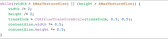
We now have a width and height that contains the power-of-two dimensions of the image and that are no larger than the maximum texture size allowed.
Generating Image Data
Having calculated a width and height that are power-of-two and are large enough to encompass our image, we need to get this data into OpenGL ES. Unfortunately, it’s not as simple as just feeding a few parameters into OpenGL ES. What we need to do is actually generate a new bitmap image of the dimensions that we have just calculated and render the image we have just loaded into this newly created image.
To do this, we are going to create a new CGContextRef called context and it will be into this context that we render this new image.
Based on the pixelFormat that we identified when loading the image, we set up a color space, storage for our bitmap data, and the context into which we are going to render the image.
The Texture2D class is using a switch statement to identify the correct configuration to use based on the pixelFormat. Listing 5.6 shows the configuration code for the kTexture2DPixelFormat_RGBA8888 pixel format.
Listing 5.6 Configure the Bitmap Context for Rendering the Texture
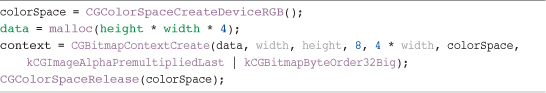
This is setting up our color space, as well as a container to hold the bitmap data of the image we are going to render called data. These are then used to set up our context.
Having configured a context into which we are going to render our image with its new OpenGL ES compatible size, we are now ready to render our image, shown in Listing 5.7.
Listing 5.7 Rendering the Texture Image
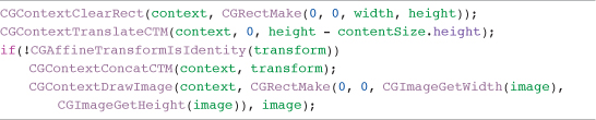
As you can see, we are clearing the context we have created and then moving the origin within that context so that the image we render is in the right place. If we have resized the image because it was larger than the maximum allowed, we then apply the scale transform created earlier.
Finally, we actually draw the bitmap image data we have loaded into the new context.
Tip
The coordinate system used in Core Animation and Quartz is different than that used in OpenGL ES. In OpenGL ES, the y-axis runs from 0 starting at the bottom of the screen and works its way up, but Core Animation is in reverse. Core Animation’s y-axis starts with 0 at the top of the screen and works its way down. This means that images loaded into OpenGL ES textures appear upside down. This is a simple issue to fix, and is covered when we examine the Image class, later in this chapter.
There is one more check to perform before creating the OpenGL ES texture. If the pixel format of the image was identified as kTexture2DPixelFormat_RGB565, we need to convert the data from 32- to 16-bits using the code in Listing 5.8. This code is taken directly from Apple’s example Texture2D class, and is found in a number of code samples.
Listing 5.8 Code Used to Convert RGP565 Image Data from 32- to 16-Bits
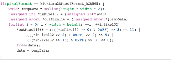
At the end of this section, we have a variable called data that contains the bitmap image data of our newly drawn image, and we know that this image has dimensions that are power-of-two, and are within the maximum size allowed. This may have seemed like a lot of code, but having Texture2D deal with these issues saves us from needing to do it manually for each new image.
Generating a Texture Name
A key step in creating an OpenGL ES texture is generating a texture name. This is an important step because the texture name enables us to tell OpenGL ES which texture we are referencing. One area of confusion is the texture name itself. From the terminology used, it sounds like you should be able to assign a descriptive name to a texture, such as “Bob” or “Shirley.” However, that’s not the case—not just because Bob and Shirley are silly names to give a texture, but because a texture name in OpenGL ES is actually a unique number, specifically a GLuint.
Now that we know that the name of a texture is actually a number, we can get OpenGL ES to generate a name for us using the following command:
![]()
The name ivar has been defined in the header file as a GLUint and is then used within the glGenTextures command to request a new texture name from OpenGL ES. You may have noticed that the command is plural and not singular (that is, textures). This is because you can ask OpenGL ES to generate more than one texture name at a time. The first parameter taken by the glGenTextures command specifies how many textures you want OpenGL ES to generate.
If you were generating more than one texture name at a time, the second parameter would point to an array of GLUint’s rather than a single GLUint.
It’s good practice to generate your textures at the start of the game rather than during game play. There’s an overhead involved in generating a texture name, not to mention the overhead of actually loading image data and associating it with a texture. To stop this from impacting performance, it is therefore normally done upfront before the game play starts.
Binding the Texture and Setting Parameters
Remember that OpenGL ES is a state engine, so before any operations can be carried out on a texture, OpenGL ES needs to know what texture the operations should be directed to. Binding the texture we want to use does this. This is the next command you see after we have generated the texture in the Texture2D class:
![]()
The first parameter is the target. When using OpenGL ES, this must be GL_TEXTURE_2D. This is because OpenGL ES only supports the GL_TEXTURE_2D target, and we will be using a two-dimensional image to create our texture. Although OpenGL supports other targets, OpenGL ES only currently supports GL_TEXTURE_2D. The second parameter is the texture name that we want to bind to, and so we provide the texture name that was previously generated.
Tip
Binding to a texture does incur an overhead, and it is therefore good practice to reduce the number of bindings you make per frame as much as possible. One way of doing this is to use a sprite sheet (texture atlas) that enables you to store many different images within a single texture. This is covered in Chapter 6, “Sprite Sheets.”
After we have told OpenGL ES which texture we want to use, we can then start to set parameters associated with that texture. When creating a new OpenGL ES texture, there are two key parameters that must to be set, as follows:
![]()
The first parameter is the target, which is the same target that we used when binding our texture. The second parameter specifies the parameter name (that is, the parameter we want to configure), and the third parameter is the actual parameter value.
The parameters we are configuring are used to define how OpenGL ES should handle images when they are being shrunk (GL_TEXTURE_MIN_FILTER) or enlarged (GL_TEXTURE_MAG_FILTER).
Other parameters can be configured, but these are the only two we need to worry about. By default, the preceding parameters are set to use something called a mipmap. A mipmap is a pre-calculated and optimized collection of images that are used with a texture. They are basically different sizes of the same image that can be used based on the size of the texture being rendered. Rather than shrinking images up and down in real time, OpenGL ES can work out which image size, from those available in the mipmap, is closest to what it needs and use that.
We are not going to be using mipmaps in our game, as the iPhone is pretty good at interpolating images on the fly using its graphics chip and FPU.
The values that can be used for these parameters are as follows:
• GL_NEAREST: Returns the value of the texture element that is nearest to the center of the pixel being textured.
• GL_LINEAR: Returns the weighted average of the four texture elements that are closest to the center of the pixel being textured. This filter should be used if you want to have your image perform sub-pixel rendering. This is important if you want your images to move smoothly at slow speeds and not only be rendered at exact pixel locations.
Put simply, GL_NEAREST gives a pixilated look to images that are scaled up or down, whereas GL_LINEAR gives you a smoother anti-aliased look.
In Texture2D, the value to be used for these parameters is taken from the filter that has been passed into the initializer method. This enables us to change the filter from one image to the next.
Tip
The value for both the minification and magnification parameters within a texture level should match. This is a restriction of the PowerVR MBX chip found on all devices prior to the iPhone 3GS, iPhone 4, and iPad. The iPhone 3GS, iPhone 4 and iPad use the PowerVR SGX chip, which does not have this restriction—nor does the iPhone Simulator.
Loading Image Data into the OpenGL Texture
We can now finish creating our OpenGL ES texture by loading the bitmap image data we generated earlier into the OpenGL ES texture to which we are currently bound.
Inside the Texture2D class, you see that we are again using a switch statement based on the pixelFormat to identify which command to use. The following OpenGL ES command loads image data into the texture for the kTexture2DPixelForm_RGBA8888 pixel format:
The parameters used in this command are as follows:
• Target: The target texture. Must be GL_TEXTURE_2D.
• Level: The level-of-detail number. Level 0 is the base image level. Level n is the nth mipmap reduction image and must be greater than or equal to zero.
• Internal format: The color components in the texture. This must be the same as the format parameter later.
• Width: The width of the texture image.
• Height: The height of the texture image.
• Border: The width of the border. Must be zero.
• Format: The format of the pixel data.
• Type: The data type used within the pixel data.
• Pixels: A pointer to the image data in memory.
On issuing the preceding command, the image data held in the data ivar is loaded into OpenGL ES and associated with the currently bound texture.
The last few actions of the Texture2D class are to set up some parameters that make it easier to manage texturing mapping.
When we looked at texture mapping earlier in this chapter, you saw that the axis names within a texture are (s, t). To finish off the creation of our texture, we are going to define our texture’s maximum s and t values. This is important, as the actual image we have loaded may be smaller than the dimensions of the texture we have created. We are therefore going to calculate the maxS and maxT values for our image within our texture.
Figure 5.9 shows an image that is 56 × 48 pixels inside an OpenGL ES-compatible texture of 64 × 64 pixels. The texture size is the smallest power-of -two size that can encompass the image we have loaded. This means that the image’s right-hand edge has an s texture coordinate of 0.875 and the top edge has a t texture coordinate of 0.75.
The last few lines of code in the Texture2D class are used to set the maxS and maxT values that give us the maximum value for the s and t. We also calculate the texture ratio for each axis. This is useful when we have a pixel location within the image, and we want to convert that to a texture coordinate. Multiplying the pixel value by the appropriate axis ratio value gives us the texture coordinate. Listing 5.9 shows these calculations in the Texture2D class.
Listing 5.9 Texture and Ratio Calculations
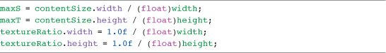
Figure 5.9 Loaded image within the generated OpenGL ES texture.
The last step is to release both the drawing context we created and also the bitmap data that was generated. This has been handed to OpenGL ES when we loaded the texture image data, so we can safely get rid of our copy:
CGContextRelease(context);
free(data);
That completes the Texture2D class. We are now going to move onto the TextureManager class, which enables us to have a single Texture2D instance shared between multiple Image instances. This helps to reduce the amount of memory consumed if multiple images require the same texture. This normally occurs when you use a sprite sheet. The sprite sheet is a single texture containing multiple smaller images. We can create many Image class instances that use the same texture, but only reference a small area of the texture by setting the appropriate texture coordinates.
Rather than having multiple instances of Texture2D, the TextureManager enables us to use a single Texture2D instance for all images taken from a sprite sheet.
TextureManager Class
The design of our rendering classes means that every texture we load will involve the creation of a Texture2D instance. Texture2D is responsible for actually loading the image we provide into an OpenGL ES compatible texture and storing the texture name, along with information such as the maximum s and t texture coordinates for later use.
The main class used when rendering images will be the Image class. When you create a new Image instance, the Image class handles the creation of the OpenGL ES texture using Texture2D. Because of the close relationship between an Image instance and Texture2D instance, there could be situations where many Image instances share the same texture.
An easy way to solve this is to create a texture manager. This singleton class will be responsible for taking requests for new textures and checking to see if a texture has already been loaded. The check will be performed on the name of the image to be loaded.
If a match is found, a reference will be returned to the texture that already exists. If no match is found, a new texture is created, cached, and passed back.
Let’s look at the TextureManager class to see how this is being done. You find the TextureManager class inside the CH05_SLQTSOR project inside the Game Engine > Managers > Texture Manager group.
Initialization
The first thing to note is that this is a singleton class. Singleton classes were covered in Chapter 4 when we looked at the GameController class. We want only a single instance of this class; making it a singleton makes sense.
Apart from setting up the class as a singleton and initializing the cachedTextures dictionary, there are no other special activities carried out during initialization.
Retrieving and Creating a Texture
TextureManager only has three methods, excluding the class method used to get the shared instance of the class.
The first method is textureWithFileName:filter:. This method is used to request a texture from the texture manager. The method accepts two parameters. The first is the file name of the image file we want to create a texture from and the second is the filter we want the texture to use. Remember from the previous section on the Texture2D class that when a texture is created, you configure the minification and magnification filters to be used. The filter we pass into this method is used to define those parameters when a texture is created. Listing 5.10 shows the textureWithFileName:filter: method.
Listing 5.10 TextureManager textureWithFileName:filter: Method

Once inside the method, the first check is to see if we can find a texture that has been created for the same image name. This is an easy check because an NSMutableDictionary, cachedTextures, was defined within the header file and allocated and initialized in the init method. All we need to do, therefore, is look for an object in the cachedTextures dictionary with a matching key.
If a match could not be found, it means we have not yet created a texture for an image with this name, and one should be created using Texture2D and adding it to the cachedTextures dictionary.
Tip
You may notice that in the preceding code, we are creating an instance of UIImage using the imageWithContentsOfFile rather than a more commonly used imageNamed. This is because when using imageNamed, iOS caches a copy of the image in memory in case it needs it later. We actually throw away the image eventually once the image data has been given to OpenGL ES, so we don’t need the image kept in memory. Using imageWithContentsOfFile does not cause this caching to happen.
That’s it for the textureWithFileName:filter: method. It’s really simple, but effective in keeping the number of textures we load in memory to a minimum.
Releasing One or All Textures
To finish off the TextureManager class, we need a couple of housekeeping methods. The first is a method that enables us to remove a texture from the cache. When we are done with a texture, it’s good to be able to remove it from the cache and free up memory. If you are using a large number of textures in your game, you may need to load a different set of textures as you transition between each scene.
With that in mind, we have the releaseTextureWithName: method. This, like the textureWithFileName: method, takes a filename and type and then looks it up in the cachedTextures dictionary. If a match is found, the object is removed from the dictionary, thereby decrementing its retain count by one. If the dictionary was the only object retaining the texture, its retain count will now be zero. Consequently, the texture will not be de-allocated and removed from memory.
The last method is releaseAllTextures. This is a simple method that just removes all objects from the cachedTextures dictionary, short and sweet.
ImageRenderManager Class
So far, we have seen the classes that turn an image into an OpenGL ES texture and manage those textures to help reduce the amount of memory we are using. The next class we discuss is ImageRenderManager, which is responsible for actually rendering images to the screen.
I mentioned at the start of this chapter that we were going to be looking at how to improve performance when using OpenGL ES. The ImageRenderManager class is fundamental to improving the performance of our game engine for Sir Lamorak’s Quest.
I’ve also mentioned already that there is an API overhead associated with using OpenGL ES commands, such as glDrawArrays and glDrawElements. There is nothing stopping us from placing the actual rendering code into our image class, making each image responsible for its own rendering. However, if you display a large number of images on the screen, you start to see performance problems due to the high volume of API calls.
A common approach to overcoming this problem is to reduce the number of these API calls. This is the purpose of the ImageRenderManager class.
Although the ImageRenderManager class is not that big, it does introduce some new concepts such as IVAs, memory structures for storing data, and the allocation of memory using functions such as calloc.
It’s also worth pointing out that this class is linked very closely to the last class we will be looking at in this chapter: the Image class. The Image class will be responsible for managing information about an image, such as its scale, rotation, location, and memory structure, that will be used by the ImageRenderManager.
The ImageRenderManager is also a singleton class. You’ve probably started to notice a singleton pattern here. We have a number of classes ending in Manager, all of which have been set up as singletons, and ImageRenderManager is no different. We need only one instance of ImageRenderManager that will be responsible for batching up and rendering our images.
Initialization
Having covered the theory behind IVAs and structures, it’s time to look at the code within the ImageRenderManager class, which uses those concepts.
If you open the ImageRenderManager.m file (found inside the Game Engine > Managers > Image Render Manager group), let’s look at how it has been implemented and the functions it provides.
As stated earlier, we are implementing the class as a singleton class. This is important, as we only want to have a single instance of this class controlling the rendering in the game. Listing 5.11 shows the init method within the ImageRenderManager class.
Listing 5.11 ImageRenderManager init Method
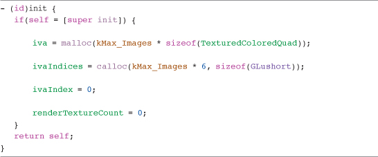
Within the init method, we allocate the memory needed to store the IVA array we are going to use. The maximum number of images the IVA can hold is defined in the header file as kMax_Images. If we needed to handle more images, we would need to increase this number to compensate. Keeping this number as small as possible will help to save memory.
You can see that we are making use of the sizeof command. When allocating the iva array, we are asking iOS to allocate enough memory to store kMax_Images multiplied by the size in bytes of the TextureColoredQuad structure. We don’t need to worry about what is in that structure and how much space it uses up; the sizeof command does that for us. In case you are interested, the TexturedColoredQuad structure actually uses 128 bytes.
The iva array is an array of TexturedColoredVertex structures and is used to store the geometry, color, and texture coordinates for each image to be rendered by the ImageRenderManager. It is this array that is used to provide OpenGL ES with the information it needs to render.
The ivaIndices array stores the indices to be used inside the iva array. As the Image class renders an image, it’s allocated the next available slot in the iva.
ivaIndex stores the next available index into the iva array, and renderTextureCount stores the number of unique textures used when rendering images. This is reset each time the ImageRenderManager renders all the images in its iva and is done when the renderImages method is called.
Adding an Image to the Render Queue
When we ask an image to render, it won’t actually be rendering anything directly to the screen. Instead, it calls the addImageDetailsToRenderQueue: method, passing in its ImageDetails structure, as shown in Listing 5.12.
Listing 5.12 ImageRenderManager addImageDetailsToRenderQueue: Method
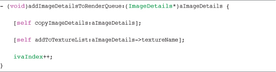
First, the copyImageDetails method is called. This method copies the image’s TextureColoredQuad structure into the iva at the next available slot. It also points the image’s TexturedColoredQuadIVA structure to this new entry. As we see when reviewing the Image class, once this copy has been done, the Image class transforms the information in the iva based on the image’s configuration. This means that the image’s TexturedColoredQuad structure holds only a clean un-transformed version of the image, and all transformations are performed on the copy within the IVA.
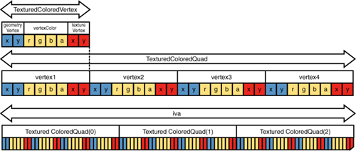
Figure 5.10 shows how each image’s TexturedColoredQuad structure is held within the iva.
Figure 5.10 Example of an iva array containing TexturedColoredQuads.
With the image copied to the IVA, call the addToTextureList: method, shown in Listing 5.13, and increment the ivaIndex.
Listing 5.13 ImageRenderManager addToTextureList: Method

Listing 5.13 checks to see if the texture name of the image being added to the render queue has already been added to the queue by another image. The texture name is taken from the ImageDetails structure, and a loop is run over the texturesToRender array.
The texturesToRender array is used to store a list of all the texture names that are used by the images that have been added to the render queue. This is a unique array of texture names, meaning that even if the same texture is used in many images, it will be added to this array only once. If a matching texture name is found in the loop, the textureFound flag is set to YES.
When we ask the ImageRenderManager to render, we move through the textures in this array, binding to them once and then rendering all images that use that texture before moving to the next. After all images in the queue have been rendered, the queue is then cleared, ready for any images that need to be rendered in the next frame.
If the texture was not found, the texture name is added to the texturesToRender array.
With the texture added if necessary, we then add the image’s ivaIndex to the textureIndices array and increment the image count for that texture.
The textureIndices ivar is a two-dimensional array that is indexed using the texture name and image count for that texture. For example, if you are processing an image using texture name 1, and it is the fifth image in the render queue that uses that texture, the image’s ivaIndex are added to the textureIndices array at [1][5].
You can see from the code that we are using another array, called imageCountForTexture, to store the number of images that have been added to the render queue for a specific texture name, with the texture name being used as the index into this array.
The textureIndices array holds all indices into the iva for images that share the same texture name. When rendering, we loop through the textureIndices array, retrieving the IVA index for each image using the current texture. These IVA indices will then be used to tell OpenGL ES which entry in the IVA should be used to render each image. This enables us to render all the images for a given texture in one go and reduce the number of texture bindings needed.
Although this method is not large, it is complex, so it’s worth re-reading this section if you are not clear on how to add images to the render queue.
Rendering Images
The last method to cover in the ImageRenderManager is renderImages: (shown in Listing 5.14), which is responsible for actually rendering images to the screen.
Listing 5.14 ImageRenderManager renderImages Method
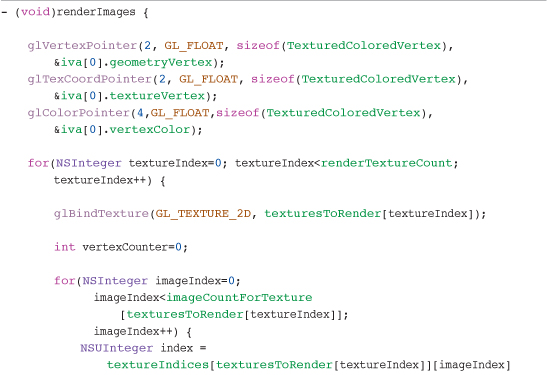
The first step in this method is to configure OpenGL ES to use the iva array for its data. These commands take a number of parameters. The first two parameters tell OpenGL ES the size of each element and the number of elements to use for describing a single item. For example, we tell OpenGL ES to use two GLFloats to describe a single vertex.
The third parameter is the stride for which we are passing the size of the TextureColoredVertex structure. The fourth parameter is a pointer to a specific member of the TexturedColoredVertex structure of the first element of the iva array—for example:
![]()
This notifies OpenGL ES where to start reading data from within the structure. This also means that the stride for each pointer is always the same (that is, the size of a TexturedColorVertex), as shown inFigure 5.11.
Figure 5.11 Strides for each element inside the iva array.
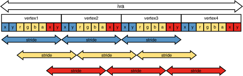
With the pointers set up so that OpenGL ES knows from where it’s reading the data, we then start to loop through the textures we have in our texturesToRender array.
The number of textures to loop through is defined by the renderTextureCount that we mentioned earlier.
Inside the loop, we bind to the current texture and set the vertexCount to zero. For each texture, the vertexCount is going to keep track of how many vertices we actually need OpenGL ES to render, which will be passed to the glDrawElements command.
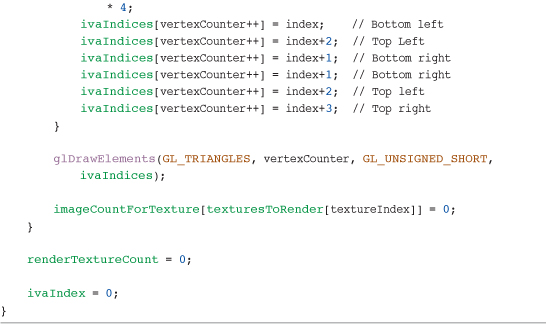
Next, we perform another loop. This loop iterates through all the images that have been added to the render queue for the current texture and populating the ivaIndices array. Each time we run through this loop, we retrieve the IVA index from the textureIndices array for the currently bound texture and image we are processing. Remember that this is the index within the iva for the first TexturedColoredVertex of the image’s TexturedColoredQuad structure.
The ivaIndices array holds a pointer to each vertex required for rendering each image. You may remember that each image we render is made up of two triangles defining a quad. This means that we need six vertices for each quad that is going to be rendered.
Having obtained the index to the first vertex in the iva array for the image we are currently processing, we add six ivaIndices entries, incrementing the index into the iva as necessary.
Because the pointers were already set up to the iva at the start of the method, all that is left is to ask OpenGL ES to draw the indices we have defined:
![]()
This is different from what we have done before. Until now, we have used glDrawArrays. The difference is that with glDrawArrays, OpenGL ES just runs sequentially through the data that has been provided from a defined start location and for a defined number of elements.
This time, we need to jump around the data that has been passed to OpenGL ES (that is, rendering the images within the IVA that share the same texture). If a large number of images are being rendered in one go, it is worth sorting the contents of the IVA array, so reducing the amount of jumping around is done for optimal performance.
The glDrawElements command does this for us. We are telling it to draw GL_TRIANGLES, which is why we need six vertices to define each quad, three vertices for each triangle. Second, we pass the vertexCounter that holds the number of vertices that are inside the ivaIndices array; finally, we tell OpenGL ES that the ivaIndices array is made up of GLUint’s and finally pass the ivaIndices array itself.
This causes OpenGL ES to render all the images for the currently bound texture, after which we clear the image count for that texture and move onto the next texture to be rendered.
Once we have finished looping through all the textures on the render queue, we then reset the renderTextureCount so the ImageRenderManager is ready to start queuing the next batch of images.
That is an awful lot to take in. The number of arrays and how we are storing our vertex data make this and the addImageDetailsToRenderQueue: method complex and a little difficult to follow.
Note
Although you don’t need to fully understand how the ImageRenderManager works to make use of it, I do recommend that you re-read this section if things are still not clear. Understanding how we are manipulating the image data inside the ImageRenderManager will be very useful, and grasping these concepts is essential to our journey into the more advanced areas of OpenGL ES.
The Image Class
We have covered a lot already in this chapter, but we have one final push before we are finished. Having built the underlying functions that enable us to create OpenGL ES textures, manage them, and render them to the screen, we now come to a key class in rendering within our game engine.
The Image class provides a wrapper around the OpenGL ES texture that has been created and stores information, such as the following:
• Position
• Scale
• Rotation
• Rotation Point
• Color
• Flip Horizontal
• Flip Vertical
• Texture Coordinates
The Image class also provides us with the API we will be using when changing these properties and asking the image to render.
If you now open the Image.m file, we’ll run through the Image class implementation.
Initialization
You’ll notice that there are two initializers for this class. The first, initWithImageNamed:filter:, is used when you are creating an image that uses the full texture provided.
The second initializer, initWithImageNamed:filter:subTexture:, is called when creating an image that is going to use a sub-region of the texture—for example, when the SpriteSheet class provides an image for a sprite.
When looking at the first initializer, you’ll see that the first task is to call a private method, initializeImage:filter:. This method is responsible for obtaining the texture for the image filename that has been passed in. This filename is passed over to the texture manager instance, which decides if either a new Texture2D object or a cached Texture2D object is passed back.
Next, we set up the base properties for the image. This involves taking information from the texture object created and storing it in local ivars, as well as setting the default values for properties, such as rotation, scale, flipHorizontal, and flipVertical. I’ve done this to reduce the amount of messaging that is needed between class instances to retrieve this info. It’s the kind of information that could be requested a lot, so reducing the amount of chatter between classes is not a bad thing.
Note
Although Apple has done a lot of work to minimize the time needed to call a method or property, there is still a small performance hit. Reducing the class messaging as much as possible in the core sections of your game will really pay off!
One item we have not covered yet is the Color4fMake function. Inside the Global.h file found in the Global Headers group are a number of macros and functions. Their use should be easy to see from the names they have been given.
When defining these functions, I am using static inline to improve performance. By making these functions inline, we are hinting to the compiler that it should put effort into calling the function faster than it would otherwise, generally by substituting the code of the function into its caller. This would remove the need for a call and return sequence and may allow the compiler to perform other optimizations between the bodies of both functions. You will see more functions added to this file as we implement other classes, such as the ParticleEmitter, later in this book.
The functions defined currently enable us to easily create new structures with a given set of values. The structures themselves are defined within the Structures.h file, which can be found in the same group as Global.h.
To store the scale of our image, we have a new type called Scale2f, with the 2f part of the name denoting that the type contains two floats. Inside Scale2f is one element called x and one called y. They store the scale to be used for each of those axes.
For storing the color of the image, we have a type called Color4f. As with Scale2f, the 4f tells us that this type contains four floats. Each float represents an element of the color being red, green, blue, and alpha, and their values can range from 0.0 to 1.0. It is also possible to store this information using GLUint’s, causing the possible values for each element to range from 0 to 255.
Getting back to the Image.m file, when the initializeImage method is complete, and having associated a texture to the image and set up the base ivars, the initWithImageNamed:filter: method sets the imageSize and textureSize.
The imageSize is the width and height in pixels of the full image inside the texture that has been created, and textureSize stores the texture.maxS and texture.maxT values that we discussed earlier in this chapter when looking at the Texture2D class.
We also set the textureOffset to zero; this initializer assumes that we want the full size of the image within the texture rather than a sub-image.
The final stage of initializing the image is to call another private method, initializeImageDetails. If the name looks familiar, it’s because it is responsible for setting up the ImageDetails structure we covered in detail earlier in this chapter. It is shown in Listing 5.15.
Listing 5.15 ImageRenderManager initializeImageDetails Method
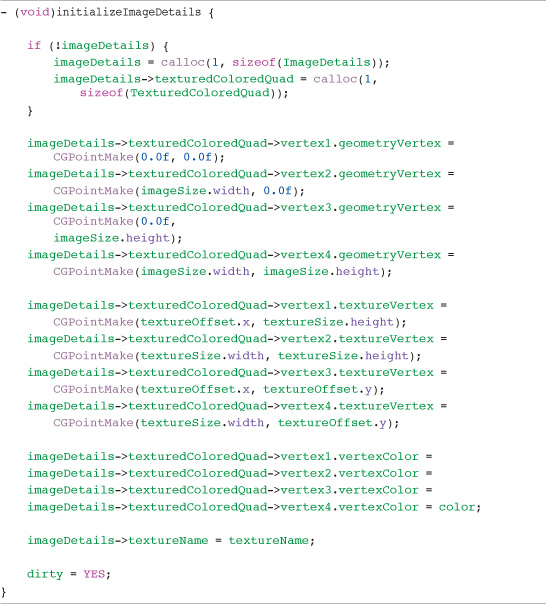
initializeImageDetails allocates memory for the ImageDetails structure. It then points the imageDetails->textureColoredQuad element to memory allocated to store the TexturedColoredQuad.
With the ImageDetails structure in place, we then set up the geometry, texture, and color details inside imageDetails->TexturedColoredQuad.
Note
You may remember from when we covered the Texture2D class that all images loaded into an OpenGL ES texture are upside down. While loading the texture coordinates into the ImageDetails structure in Listing 5.15, you can reverse the yaxis coordinates so the images appear correctly onscreen.
You can see from the code that we are using the image’s instance properties for setting up the data inside the imageDetails structure. This allows the same method to be called when creating an image using the full texture size or an image that defines a sub-image within a larger image.
The final steps in this method set the imageDetails->textureName to the texture name and the dirty flag is set to YES. This flag tells the image that certain properties have been changed (that is, rotation, scale, position, and so on). This causes the image to recalculate the vertices held within the ImageRenderManager IVA using matrix transformation functions, which we look at shortly.
You’ll remember that there were two initializers for the Image class. The second of those is initWithImageNamed:filter:subTexture:. This performs the same basic functions as the previous initializer. The key difference is that an extra parameter is passed into the method called subTexture. This parameter takes a CGRect that defines an area in pixels inside the image’s texture. This enables us to create an image that has dimensions of the rectangle specified. Only the area within these dimensions will be displayed when the image is rendered.
This provides us with the base functions needed to support new classes, such as the SpriteSheet class, where we need to be able to create an image that only represents a small area of the original texture.
In this method, rather than set the textureOffset to zero and the textureSize to the maximum, the dimensions of the CGRect are used instead.
Notice that we are using the texture’s textureRatio value to calculate the texture coordinates for the sub-image by multiplying the textureRatio with the specified pixel values.
Retrieving a Sub-Image
We have mentioned the SpriteSheet class a number of times, along with the need to be able to create an image using a sub-region within a large texture. The Image class can help us do this because it contains all the information we need to generate such an image.
The subImageInRect: method, shown in Listing 5.16, accepts a CGRect that is used to define a region within the texture of the image. A new Image is created that is configured to only render the region specified.
Listing 5.16 ImageRenderManager subImageInRect: Method

The method itself is pretty basic. It creates a new Image instance called subImage using the initWithImageNamed:filter:subTexture: method. This enables us to pass in the CGRect, and we end up with a new Image instance that represents just that region of the texture.
Next, we set the properties of that new image to match those of the parent image and then return the subImage and autorelease it.
Auto-releasing subImage is important. It is not the responsibility of the Image class but of the requester to retain subImage. For this reason, the Image class should release the image at some point, whereas the requester should retain it.
Duplicate an Image
Another useful function is the ability to duplicate an image, as shown in Listing 5.17.
Listing 5.17 The imageDuplicate Method
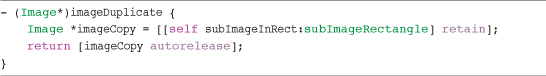
This is a convenience method, as it needs to perform the same actions that the subImageInRect: method does but without taking a CGRect as a parameter. Instead, it uses the subImageRectangle property of the Image class to call the subImageInRect: method. The image returned needs to be retained, as it could be auto-released before being passed onto the caller. When imageCopy is returned, the autorelease reduces the retain count as necessary.
Rendering an Image
Now that we have covered how an Image instance is created, it’s time to look at how we actually render an image. You’ll see from the Image.h file that a number of methods can be used to render an image, as follows:
• renderAtPoint:
• renderAtPoint:scale:rotation:
• renderCentered:
• renderCenteredAtPoint:
• renderCenteredAtPoint:scale:rotation:
These are convenience methods, used to make the process of rendering an image to the screen easier. The majority of these methods are simply setting the properties of the image before it is rendered. Listing 5.18 shows the renderCenteredAtPoint:scale:rotation: as an example.
Listing 5.18 The renderCenteredAtPoint:scale:rotation: Method
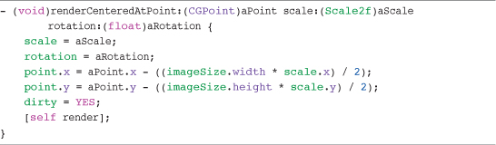
This method takes in a CGPoint, defining the pixel location the image should be rendered to, as well as a Scale2f value and a rotation value that specifies the number of degrees the image should be rotated.
The image’s scale and rotation are set to the values passed in and then the image’s point is calculated to make sure that the image will be rendered with its center at the point provided. This calculation also takes into account the scale to be used so that the correct center point is still calculated.
You see that all the rendering methods follow the same pattern, except for the render method. This method actually calculates the rotation, scaling, and translation necessary on the image’s vertices and then adds the image to the ImageRenderManager render queue. The render method is shown in Listing 5.19.
Listing 5.19 The render Method
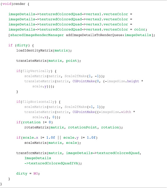
The first task of the method is to set the TextureColoredQuad color to the current color of the image. When this is done, the image is added to the ImageRenderManagers render queue.
The next check is to see if the image is marked as dirty. Remember from earlier that when we change something like the image’s scale or rotation, the dirty flag is set to YES. This enables us to perform transforms only on the image’s vertices if they have changed. If there is no change, we can simply use the values from the last render and move on.
If, however, the image has been marked as dirty, we calculate the transformations that need to be done.
These transformations are calculated using our own transformation functions. OpenGL ES has its own transform and matrix functions, such as glLoadIdentity, glScale and glRotate, but these can only be set once before a glDrawElements is called. As we have seen, when we covered the ImageRenderManager, we are rendering all the images for a texture using just a single glDrawElements command, so there is no possibility to call the OpenGL ES transforms between each image.
The solution to this is to actually transform the vertices information for the image directly, and it is for this reason that we have two TexturedColoredQuads inside the image’s ImageDetails structure.
As you may remember from earlier, imageDetails->texturedColoredQuad holds the base information for the image (that is, its origin is 0,0, and it is not scaled or rotated). The second TexturedColoredQuad inside ImageDetails called texturedColoredQuadIVA points to an entry in the ImageRenderManager’s IVA. Having these two copies enables us to transform the vertice’s information inside the imageDetails->TexturedColoredQuad and place the results inside imageDetails->texturedColoredQuadIVA.
When the ImageRenderManager then renders, it will be rendering the image with any scale, rotation, or translation applied without the need to use the OpenGL ES transform functions.
There are a few things needed to make this magic happen. The first is that each image has to have its own matrix, which is used to perform the transform calculations. This is defined within the Image.h file and is an array of nine floats called matrix.
The next requirement is the actual transform functions themselves. If you look inside the Transform2D.h file inside the Global Headers group, you see the transform functions we are using. I’m not going to run through these functions in detail or try to describe the matrix math.1 They are not doing anything special apart from applying matrix calculations to the data that is passed in. These functions are also inline, as were the functions in the Global.h file. This again is to improve performance, as described earlier.
So, knowing that we have the necessary functions to transform the vertices, we can go back to the Image.m file and finish off looking at the render method.
Inside the render method we have just performed a check to see whether an image is dirty; now we’ll perform the transform calculations.
First, the images matrix is reset by loading the identity matrix. Then, a translation is performed on the matrix using the image’s point information. Next, a check is carried out to see if the image has been flipped horizontally or vertically. If so, a simple scale transform is done using -1 on the axis being flipped. A translation is also performed to make sure that the images position is updated to match its new orientation.
If the image has been rotated, the rotation transform is calculated followed by the scale transform if necessary. After these have all been done, the resulting matrix is multiplied against the vertices inside imageDetails->texturedColoredQuad, with the results being loaded into imageDetails->texturedColoredQuadIVA. Finally, the dirty flag is set to NO.
Getters and Setters
The last few methods we need to cover in the Image class are some getters and setters. We could have just used those generated by @synthesize, but we need to not change only the value of the property but also set the dirty flag. Because we need to set this flag, we need to create our own getters and setters, as shown in Listing 5.20.
Listing 5.20 Getters and Setters
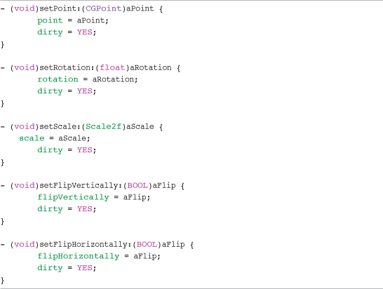
These simple methods are setting the image’s properties to the values passed in. The only extra piece that gets added is setting of the dirty flag.
Summary
This is a large chapter, and the concepts and code we have run through have been complex in places. Although the actual task of rendering something to the screen using OpenGL can be done in just a few commands, it’s the infrastructure we have built around those commands that is going to make our lives easier as we implement the game logic.
Although it can take a great deal of time to get your game engine working as you would like, without having implemented any of your actual game logic, it is time well spent. Putting in the time now to make your core classes functional and clean to use will save you plenty of time in the long run.
This chapter is a milestone on our journey to creating Sir Lamorak’s Quest. Being able to load any image and render it to the screen, applying scale, rotation, and transparency, is the backbone of any game engine. Now that we have the game’s spine, we can start to hook up the other bones that form the game engine and eventually become Sir Lamorak’s Quest.
Exercise
If you run the project that accompanies this chapter, you see that you are presented with a still image and a rotating scaling image. All the logic needed to make this happen is inside the GameScene class, introduced in Chapter 4.
Having a spinning, scaling image is pretty cool, but how about making it do something different?
As a suggestion, how about making the spinning image bounce around the screen so that when the center of the image reaches the edge of the screen, it bounces off. You already have all you need to render the image; you just need to add some more logic to handle the movement and bouncing.
You could also try changing the image being used in the project as well, or load more images and have them render to the screen.
Tip
When adding any files to your project, make sure you right-click within Xcode’s Groups & Files section and select Add Existing File. This ensures that the file is registered with the project, or else your code will not be able to see your file, even if it is where you expect it to be.
If you get stuck trying to make your image bounce, check out the project called CH05_SLQTSOR_EXERCISE to see how it can be done.