
LEARNING OBJECTIVES
To appreciate the role of software architecture in software development
To understand the relation between software architecture and design decisions
To be able to document a software architecture in different views
To be able to characterize some important software architectural styles
To understand the role and purpose of software architecture assessments
Note
Software architecture concerns the large-scale structure of software systems. This large-scale structure reflects the early, essential design decisions. The decision process involves negotiating and balancing functional and quality requirements on the one hand and possible solutions on the other hand. Software architecture is not a phase strictly following requirements engineering, but the two are intertwined. In this chapter, we discuss how to design, document, and evaluate software architectures.
A good design is the key to a successful product. Almost 2 000 years ago, the Roman architect Vitruvius recorded what makes a design good: durability (firmitas), utility (utilitas), and charm (venustas). These quality requirements still hold, for buildings as well as software systems. A well-designed system is easy to implement, is understandable and reliable, and allows for smooth evolution. Badly designed systems may work at first, but they are hard to maintain, difficult to test, and unreliable.
During the design phase, the system is decomposed into a number of interacting components. The top-level decomposition of a system into major components together with a characterization of how these components interact, is called its software architecture. Viewed this way, software architecture is synonymous with global design. There is, however, more to software architecture than mere global design.
Software architecture serves three main purposes:
It is a vehicle for communication among stakeholders. A software architecture is a global, often graphic, description that can be communicated to the customers, end users, designers, and so on. By developing scenarios of anticipated use, relevant quality aspects can be analyzed and discussed with various stakeholders. The software architecture also supports communication during development. It can be used to develop a skeletal version of the system. This skeletal version contains all of the architecture's components in a rudimentary form. The skeletal system can be used as an environment for the incremental implementation of the system. It can also be used as an environment (test harness) for testing the system.
It captures early design decisions. In a software architecture, the global structure of the system has been decided upon, through the explicit assignment of functionality to components of the architecture. These early design decisions are important since their ramifications are felt in all subsequent phases. It is therefore paramount to assess their quality at the earliest possible moment. By evaluating the architecture, a first and global insight into important quality aspects can be obtained. The global structure decided upon at this stage also structures development: the work-breakdown structure may be based on the decomposition chosen at this stage, testing may be organized around this same decomposition, and so on.
It is a transferable abstraction of a system. The architecture is a basis for reuse. Design decisions are often ordered, from essential to nice features. The essential decisions are captured in the architecture, while the nice features can be decided upon at a later stage. The software architecture thus provides a basis for a family of similar systems, a product line; see also Chapter 18. The global description captured in the architecture may also serve as a basis for training, e.g. to introduce new team members.
The traditional view holds that the requirements fully determine the structure of a system. Traditional design methods as discussed in Chapter 12 work that way. Their aim is to systematically bridge the gap between the requirements and some blueprint of an operational system in which all of the requirements are met. It is increasingly being recognized that other forces influence the architecture (and, for that matter, the design) as well:
Architecture is influenced by the development organization. In our library example, for example, the hardware and software for reading bar codes might be subcontracted to some organization having special expertise in that area. There will then be one or more system components with externally dictated functionality and interfaces to deal with this part of the problem. If an organization deploys one or more systems with a certain architecture, (maintenance) expertise will be structured according to the decomposition chosen in that architecture and there will be a pressure to have future systems follow that same architecture.
Architecture is influenced by the background and expertise of the architect. If an architect has a positive experience with, say, a layered architecture, he is likely to use that same approach on his next project.
Architecture is influenced by its technical and organizational environment. In financial applications, for instance, government rules may require a certain division of functionality between system components. In embedded systems, the functionality of hardware components may influence the functionality of and interaction between software components. Finally, the software engineering techniques prevalent in the development organization will exert influence on the architecture.
This mutual influencing between an architecture and its environment is a cyclical process, known as the architecture business cycle (ABC) (Bass et al., 2003). For example, an architecture yields certain units of work, corresponding to the components distinguished in the architecture. If the same components occur over and over again, expertise will be organized according to the functionality embedded in these components. The development organization may then become expert in certain areas. This expertise then becomes an asset which may affect the goals of the development organization. The organization may try to develop and market a series of similar products in which this expertise is exploited.
Traditional design is inward-looking: given a set of requirements, how can we derive a system that meets those requirements. Software architecture has an outward focus as well: it takes into account how the system fits into its environment. Software architecting includes negotiating and balancing of functional and quality requirements on one hand, and possible solutions on the other hand. This is further elaborated in Section 11.1. Balancing requirements also requires that the candidate software architecture is assessed. This is a form of testing, discussed in Section 11.5.
One of the early definitions of software architecture is (Shaw et al., 1995):
The architecture of a software system defines that system in terms of computational components and interactions among those components.
A more recent definition is (Bass et al., 2003):
The software architecture of a program or computing system is the structure or structures of the system, which comprise software elements, the externally visible properties of those elements, and the relationships among them.
The latter definition reflects, among others, the insight that there may be more than one structure that is of interest. In house construction, we use different drawings: one for the electrical wiring, one for the water supply, etc. These drawings reflect different structures which are all part of the same overall architecture. We generally observe the architecture through one of these more specific views. The same holds for software architecture. This is further elaborated in Section 11.3.
In the software architecture, the global structure of the system has been decided upon. This global structure captures the early, major design decisions. Whether a design decision is major or not really can only be ascertained with hindsight, when we try to change the system. Only then will it show which decisions were really important. A priori, it is often not at all clear if and why one design decision is more important than another (Fowler, 2003). For instance, we may decide to separate the user interface from the processing part and store data about books in a flat file in our library system. Both decisions could be important but they need not be. Separating the user interface from the processing part is generally considered good design. If, at a later stage, changes occur in either part, we will be glad to have made this decision. If no such changes occur, the decision was not all that important, after all. Deciding to use flat files to store data in our library system may turn out to have been important if our library grows and we are forced to switch to database storage of data. But again, if no such change occurs, the decision wasn't that important either.
Viewed this way, the architectural design process is about making the important design decisions. Next, these important design decisions need to be documented. Both the process of making architectural decisions and their documentation for later use are discussed in Section 11.2.
A very active field of research these days is aimed at identifying and describing components at a higher level of abstraction, i.e. above the level of a module or abstract data type. These higher-level abstractions are known as design patterns and software architectural styles (or architectural patterns).
Part of the work in software architecture is aimed at characterizing and classifying these software architectural styles, as well as developing appropriate notations and supporting tools. The ultimate goal is that the resulting abstractions become part of the vocabulary of software engineers, in much the same way as abstract data types are already part of that vocabulary. Section 11.4 gives an overview of the major issues involved in software architectural styles. Design patterns are further discussed in Chapter 12.
Today's work in software architecture is broad in scope. Almost any topic in software engineering is being rethought in architectural terms. The discussion in this chapter is focused on how to design, name, document, and assess software architectures.
If software architecture is just global design, we would be selling old wine in new bottles. The design phase then is simply split into two subphases: architectural, global design and detailed design. The methods used in these two subphases might be different, but both essentially boil down to a decomposition process, taking a set of requirements as their starting point. Both design phases then are inward-looking: starting from a set of requirements, derive a system that meets those requirements.
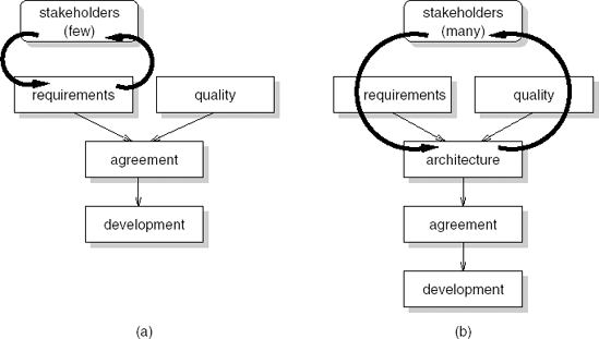
A 'proper' software architecture phase however has an outward focus as well. It includes the negotiating and balancing of functional and quality requirements with possible solutions. This means requirements engineering and software architecture are not consecutive phases that are more or less strictly separated, but instead they are heavily intertwined. An initial set of functional and quality requirements is the starting point for developing an initial architecture. This initial architecture results in a number of issues that require further discussion with stakeholders. For instance, the envisaged solution may be too costly, integration with existing systems may be complex, maintenance may be an issue because of a lack of staff with certain expertise, or performance requirements cannot be met. These insights lead to further discussions with stakeholders, a revised set of requirements, and a revised architecture. This iterative process continues until an agreement is reached. Only then will detailed design and implementation proceed. The difference between these two paradigms is illustrated in Figure 11.1.
We thus see important differences between traditional process models that do not pay specific attention to software architecture and process models that do pay attention to software architecture:
In traditional models, iteration only concerns functional requirements. Once the functional requirements are agreed upon, design starts. In process models that include a software architecture phase, iteration involves both functional and quality requirements. Only when the combined set of functional and quality requirements is agreed upon will development proceed.
Traditional models involve negotiation with a few stakeholders only. Usually, only the client and end users are involved. Negotiations about architectural solutions may involve a much larger variety of stakeholders and include, for instance, the future maintenance organization for the system to be developed and owners of other systems that this system has to interact with.
In traditional models there is no balancing of functional and quality requirements. Once the functional requirements are agreed upon, development proceeds and it is assumed that quality requirements can be met. If it turns out that the quality requirements cannot be met, the project gets into trouble. Deadlines slip, functionality is skipped, more hardware is bought, etc. In process models that include a software architecture phase, there is a balancing of functional and quality requirements at an early stage.
Design is a problem-solving activity and, as such, is very much a matter of trial and error. In the presentation of a mathematical proof, subsequent steps dovetail well into each other and everything drops into place at the end. The actual discovery of the proof probably went quite differently. The same holds for the design of software. We should not confuse the outcome of the design process with the process itself. The outcome of the design process is a 'rational reconstruction' of that process. (Note that we made precisely the same remark with respect to the outcome of the requirements engineering process.)
During design, the system is decomposed into parts that each have a lower complexity than the system as a whole, while the parts together solve the user's problem. The design problem can now be formulated as follows: how to determine this decomposition. There really is no universal method for this. The design process is a creative one, and the quality and expertise of the designers is a critical determinant for its success. Yet, during the course of the years, a number of ideas and guidelines have emerged which may serve us in designing software. These have resulted in a large number of design methods, which are the topic of Chapter 12.
In a similar vein, architectural design methods have been developed. A good example is attribute-driven design (ADD), described in (Bass et al., 2003). The input to the ADD process are the requirements, formulated as a set of prioritized quality attribute scenarios. A quality attribute scenario is a scenario as known from requirements engineering, but whose description explicitly captures quality information; see also Section 6.3.
ADD is described as a top-down decomposition process. In each iteration, one or a few components are selected for further decomposition. In the first iteration, there is only one component, 'the system'. From the set of quality attribute scenarios, an important quality attribute is selected that will be handled in the current refinement step. For instance, in our library system, we may have decided on a first decomposition of the system into three layers: a presentation layer, a business logic layer, and a data layer. In a further ADD step, we may decide to decompose the presentation layer, and select usability as the quality attribute that drives this decomposition. A pattern is then selected that satisfies the quality attribute. For instance, a data validation pattern (Folmer et al., 2003) may be applied to verify whether data items have been entered correctly. Finally, the set of quality attribute scenarios is verified and refined to prepare for the next iteration.
ADD gives little guidance for the precise order and kind of refinement steps. This is very much a matter of the architect's expertise. The same rather global support is given by other architecture design methods, as discussed by (Hofmeister et al., 2007). The global workflow common to these methods is depicted in Figure 11.2. At the centre, is the backlog, which contains a list of issues to be tackled, open problems, ideas that still have to be investigated, and so on. The name derives from Scrum, an agile method (Schwaber and Beedle, 2002). There, the backlog drives the project. In (architecture) design projects, the notion of a backlog is usually not represented explicitly. Yet, it is always there, if only in the head of the architect. There are three inputs to the backlog: context, requirements, and evaluation results. The context refers to such things as ideas the architect may have, available assets that can be used, constraints set, and so on. Obviously, the requirements constitute another important input. In each step of the architecting process, one or a few items from the backlog are taken and used to transform the architecture developed so far. The result of this transformation is evaluated (usually rather informally) and this evaluation may in turn change the contents of the backlog. New items (for instance, new problems) may be added, items may disappear or become obsolete, and the priorities of backlog items may change.
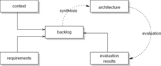
Figures 11.1b and 11.2 describe the same iterative process. Whereas the former emphasizes interactions with external parties, the latter emphasizes the architectural design process itself. The latter process model is also more finegrained. Many of the iterations involving one or more items of the backlog, a synthesis step, evaluation of the result, and updating the backlog, will be done by the architect and not involve communication with other stakeholders. But once in a while, communication with other stakeholders takes place, and this is the level at which Figure 11.1b applies.
The architecture design process is very much driven by the architect's experience, much more so than by any of the 'architecture design' methods. An experienced architect knows how to handle a given issue, rather than some method telling him how to perform a design iteration. This is also true for the design methods discussed in Chapter 12 that are applied at the more detailed levels of design. Their descriptions usually give much more guidance than those for architecture design methods but this guidance is mostly used by inexperienced designers. Since architecture design is usually done by experienced designers, the amount of guidance given, and needed, is less. Attention then shifts to techniques for documenting the result of the design process: the decisions, their rationale, and the resulting design.
If architecture is the set of design decisions, then documenting the architecture boils down to documenting the set of design decisions. This is usually not done fully, though. We can usually get at the result of the design decisions, the solutions chosen, but not at the reasoning behind them. Much of the rationale behind the solutions is lost forever or resides only in the heads of the few people associated with them, if they are still around.
So the reasoning behind a design decision is not explicitly captured. This is tacit knowledge, essential for the solution chosen, but not documented. At a later stage, it then becomes difficult to trace the reasons of certain design decisions. In particular, during evolution one may stumble upon these design decisions, try to undo them or work around them, and get into trouble when this turns out to be costly if not impossible.
There are different types of undocumented design decisions:
The design decision is implicit: the architect is unaware of the decision or it concerns 'of course' knowledge. Examples include prior experience, implicit company policies to use certain approaches, standards, and so on.
The design decision is explicit but undocumented: the architect takes a decision for a very specific reason (e.g. using a certain user-interface policy because of time constraints). The reasoning is not documented and thus is likely to vaporize over time.
The design decision is explicit and explicitly undocumented: the reasoning is hidden. There may be tactical company reasons to do so or the architect may have personal reasons (e.g. to protect his position).
It is a fantasy to want to document all design decisions. There are far too many of them and not all of them are that important. Documenting design decisions takes time and effort from the architect, a very busy person. But we may try to document the really important decisions.
A design decision addresses one or more issues that are relevant to the problem at hand. There may be more than one way to resolve these issues, so that the decision is a choice from amongst a number of alternatives. The particular alternative selected preferably is chosen because it has some favorable characteristics. That is, there is a rationale for our particular choice. Finally, the particular choice made may have implications for subsequent decision making. Table 11.1 gives a template for the types of information that is important to capture for each design decision.
Table 11.1. Elements of a design decision
Element | Description |
|---|---|
Issues | Design issues being addressed by this decision |
Decision | The decision taken |
Status | The status of the decision, e.g. pending, approved |
Assumptions | The underlying assumptions about the environment in which the decision is taken |
Alternatives | Alternatives considered for this decision |
Rationale | An explanation of why the decision was chosen |
Implications | Implications of this decision, such as the need for further decisions or requirements |
Notes | Any additional information one might want to capture |
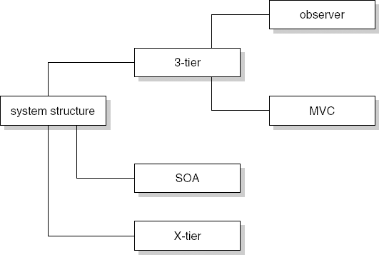
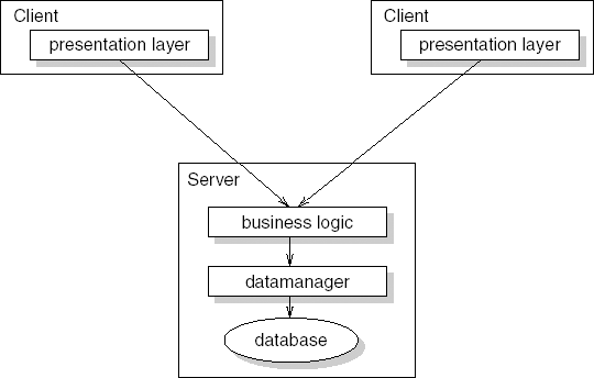
Table 11.2 gives an example of a design decision for our library application. It concerns the choice of a three-tier architecture, consisting of a presentation layer, a business logic layer, and a data management layer.
Table 11.2. Example of a design decision
Element | Description |
|---|---|
Issues | The system has to be structured so that it is maintainable, reusable, and robust. |
Decision | A three-tier architecture, consisting of a presentation layer, a business logic layer, and a data management layer. |
Status | Approved. |
Assumptions | The system has no hard real-time requirements. |
Alternatives | A service-oriented architecture (SOA) or a different type of X-tier architecture (e.g. one with a fat client including both presentation and business logic, and a data management tier). |
Rationale | Maintenance is supported and extensions are easy to realize because of the loose coupling between layers. Both the presentation layer and the data management layer can be reused in other applications. Robustness is supported because the different layers can easily be split over different media and well-defined layer interfaces allow for smoother testing. |
Implications | Performance is hampered since all layers have to be gone through for most user actions. |
Notes | None. |
Design decisions are often related. A given design decision may constrain further decisions, exclude or enable them, override them, be in conflict with them, and so on. These relationships between design decisions resemble the kind of relationships that may exist between requirements, as discussed in Section 9.1.3. And likewise, the notations and tools used to capture this information are very similar as well. A simple way to structure design decisions hierarchically is in the form of a decision tree (see Figure 11.3).
A software architecture serves as a vehicle for communication among stakeholders. Example stakeholders are: end users of the anticipated system, security experts, representatives from the maintenance department, owners of other systems that this system has to interface with, software developers, and of course the architect himself. These stakeholders all have a stake, but the stakes may differ. End users will be interested to see that the system will provide them with the functionality asked for. Software developers will be interested to know where to implement this functionality. Maintainers want to assure themselves that components are as independent as possible.
In some cases, it may be possible to devise one single architecture representation that serves all these stakeholders. In general, this will not work, though. A specific stakeholder is best served by a representation of the software architecture that highlights his concerns. Just think of civil engineering, where one representation may highlight the outer appearance of a structure while another highlights construction aspects.
IEEE Standard 1471 (IEEE1471, 2000) gives a general structure for software architecture representations. The main elements from this standard are:
stakeholder: an individual, team, or organization (or classes hereof) with interests in, or concerns relative to, a system;
view: a representation of a whole system from the perspective of a related set of concerns;
viewpoint: the purposes and audience for a view and the techniques or methods employed in constructing a view.
So the stakeholder concerns determine which representations (views) are appropriate for a specific software architecture. Each view has a corresponding viewpoint which gives the 'syntax' of the view, much like a construction drawing has an accompanying description telling what all the glyphs in the drawing mean.
(IEEE1471, 2000) does not tell you which viewpoints to use. In essence, it suggests we develop an appropriate set of viewpoints for each separate software architecture. It does have the notion of a library viewpoint, though, a viewpoint that might be useful across different software architectures. (Bass et al., 2003) give a collection of viewpoints that is useful across a wide variety of software architectures. These viewpoints fall into three classes:
Module viewpoints give a static view of the system. They are usually depicted in the form of box-and-line diagrams where the boxes denote system components and the lines denote some relation between those components. Table 11.3 describes typical module viewpoints.
Component-and-connector viewpoints give a dynamic view of the system, i.e. they describe the system in execution. Again, they are usually depicted as box-and-line diagrams. Table 11.4 describes typical component-and-connector viewpoints.
Allocation viewpoints give a relation between the system and its environment, such as who is responsible for which part of the system. Table 11.5 gives typical allocation viewpoints.
Of course, you do not use all these viewpoints for a single software architecture. Usually, one from each category will suffice. You may for instance choose the decomposition, deployment, and work-assignment viewpoints. It is also possible to combine viewpoints. In Figure 11.4 we have combined the decomposition viewpoint and the client-server viewpoint to create a view of our library system. In specific cases, additional architectural views may be helpful or needed. In systems for which the user interface is of critical importance, a separate user-interface view may be developed; in electronic commerce applications, a view highlighting security aspects may come in handy; and so on.
Table 11.3. Module viewpoints
Viewpoint | Description |
|---|---|
Decomposition | Elements are related by the 'is a submodule of' relation. Larger elements are composed of smaller ones. It is the result of a top-down refinement process. The decomposition viewpoint often forms the basis for the project organization and the system's documentation. It is the viewpoint we are most used to in software design. |
Uses | The relation between elements is 'uses' (A calls B, A passes information to B, etc.). The uses relation goes back to Parnas (1972); see also Chapter 12. The uses relation is important when we want to assess modifiability: if an element is changed, all elements it is used by potentially have to be changed as well. It is also useful to determine incremental subsets of a system: if an element is in a given subset, all elements it uses must also be in that subset. |
Layered | This is a special case of the uses viewpoint. It is useful if we want to view the system as a series of layers, where elements from layer n can only use elements from layers < n. Layers can often be interpreted as virtual machines. |
Class | Elements are described as a generalization of other elements. The relation between elements is 'inherits from'. It is obviously most applicable for object-oriented systems. |
Table 11.4. Component-and-connector viewpoints
Viewpoint | Description |
|---|---|
Process | The system is described as a series of processes, connected by communication or synchronization links. It is useful if we want to reason about the performance or the availability of the system. |
Concurrency | To determine opportunities for parallelism, a sequence of computations that can be allocated to a separate physical thread later in the design process is collected in a 'logical thread'. It is used to manage issues related to concurrent execution. |
Shared data | Describes how persistent data is produced, stored, and consumed. It is particularly useful if the system centers around the manipulation of large amounts of data. It can be used to assess qualities such as performance and data integrity. |
Client-server | Describes a system that consists of cooperating clients and servers. The connectors are the protocols and messages that clients and servers exchange. This viewpoint expresses separation of concerns and physical distribution of processing elements. |
Table 11.5. Allocation viewpoints
Viewpoint | Description |
|---|---|
Deployment | Shows how software is assigned to hardware elements and which communication paths are used. It allows one to reason about, e.g., performance, security, and availability. |
Implementation | Indicates how software is mapped onto file structures. It is used in the management of development activities and for build processes. |
Work assignment | Shows who is doing what and helps to determine which knowledge is needed where. For instance, one may decide to assign functional commonality to a single team. |
Many organizations have developed their own set of library viewpoints. A well-known set of library viewpoints is known as the '4 + 1 model' (Kruchten, 1995). It consists of the following viewpoints:[10]
a conceptual, or logical, viewpoint that describes the system in terms of major design elements and their interactions;
an implementation viewpoint that gives a view of the system in terms of modules or packages and layers;
a process viewpoint that describes the dynamic structure of the system in terms of tasks, processes, their communication, and the allocation of functionality to run-time elements; this view is only needed if the system has a significant degree of concurrency;
a deployment viewpoint that contains the allocation of tasks to physical nodes; this view is only needed if the system is distributed.
The '+1' viewpoint is a set of important use cases. This set of use cases drives the architectural design and serves as glue to connect the other four viewpoints. The '4 + 1 model' is part of the RUP development methodology (Kruchten, 2003).
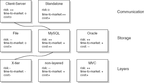
The above viewpoints are all technical in nature. Often, it is also useful to construct one or more viewpoints which emphasize business concerns. Figure 11.5 gives a business-oriented view of our library system. It addresses three aspects of the architecture: communication, storage, and layers. For each, several alternatives are given and, for each alternative, the risk, time to market, and cost are indicated. One alternative for each aspect is chosen. These alternatives are connected by curved lines. In this way, a quick overview is obtained. The view is easy to grasp, especially so for non-technical stakeholders.[11]
One interesting theory of problem-solving in the programming domain states that programmers solve such problems using programming plans, program fragments that correspond to stereotypical actions, and rules that describe programming conventions. For example, to compute the sum of a series of numbers, a programmer uses the 'running total loop plan'. In this plan, some counter is initialized to zero and is incremented with the next value of a series in the body of a loop. Experts tend to recall program fragments that correspond to plan structures before they recall other elements of the program. This nicely maps onto the idea that knowledge is stored in human memory in meaningful units (chunks).
An expert programmer has at his disposal a much larger number of knowledge chunks than a novice programmer. This concerns both programming knowledge and knowledge about the application domain. Both during the search for a solution and during program comprehension, the programmer tries to link to knowledge already present. As a corollary, part of our education as a programmer or software engineer should consist of acquiring a set of useful knowledge chunks.
At the level of algorithms and abstract data types, such a body of knowledge has been accumulated over the years and has been codified in text books and libraries of reusable components. As a result, abstractions, such as QuickSort, embodied in procedures, and abstract data types, such as Stack and BinaryTree, have become part of our vocabulary and are routinely used in our daily work.
The concepts embodied in these abstractions are useful during the design, implementation, and maintenance of software for the following reasons:
They can be used in a variety of settings and can be given unique names. The names are used in communicating the concepts and serve as labels when retrieving and storing them in human memory. The label
QuickSortrings the same bell for all people working in our field.We have notations and mechanisms to support their use and reuse, such as procedure calls and the module concept.
We have organized related concepts into (semantic) networks that can be searched for an item that fits the problem at hand. For example, we know the time and space tradeoffs between
QuickSortandBubbleSortor between a standard binary search tree and an AVL-tree, and we know the grounds on which to make a choice.
Design patterns are collections of a few modules (or, in object-oriented circles, classes) that are often used in combination, and which together provide a useful abstraction. A design pattern is a recurring solution to a standard problem. The prototypical example of a pattern is the Model-View-Controller (MVC) pattern from Smalltalk. We may view design patterns as micro-architectures. Design patterns are further discussed in Section 12.5.
Two further notions often used in this context are (application) framework and idiom. An application framework is a partially complete system which needs to be instantiated to obtain a complete system. It describes the architecture of a family of similar systems. It is thus tied to a particular application domain. The best-known examples are frameworks for building user interfaces. An idiom is a low-level pattern, specific to some programming language. For example, the counted-pointer idiom (Buschmann et al., 1996, pp. 353–8) can be used to handle references to objects created dynamically in C++. It keeps a reference counter which is incremented or decremented when references to an object are added or removed. Memory occupied by an object is freed if no references to that object remain, i.e. when the counter becomes zero. Frameworks and idioms thus offer solutions that are more concrete and language-specific than the architectural styles and design patterns we will discuss.
Work in the area of software architecture and design patterns has been strongly influenced by the ideas of the architect Christopher Alexander, as formulated in (Alexander, 1979) and (Alexander et al., 1977). The term 'pattern' derives from Alexander's work and the format used to describe software architectural styles and design patterns is shaped after the format Alexander used to describe his patterns, such as 'alcove', 'office connection' or 'public outdoor room'. In software engineering, we often draw a parallel with other engineering disciplines, in particular civil engineering. This comparison is made to highlight both the similarities, such as the virtues of a phased approach, and the differences, such as the observation that software is logical rather than physical, which hampers the control of progress. The comparison with the field of architecture is often made to illustrate the role of different views, as expressed in the different types of blueprint produced. Each of these blueprints emphasizes a particular aspect.
The classical field of architecture provides some further interesting insights for software architecture. These insights concern:
the notion of architectural style,
the relationship between style and engineering, and
the relationship between style and materials.
Architecture is a (formal) arrangement of architectural elements. An architectural style abstracts from the specifics of an architecture. The decomposition of our library system might, for instance, result in an architecture consisting of one main program and four subroutines, sharing three data stores. If we abstract from these specifics, we obtain its architectural style, in which we concentrate on the types of its elements and their interconnections.
Viewed in this way, an architectural style describes a certain codification of elements and their arrangement. Conversely, an architectural style constrains both the elements and their interrelationships. For example, the Tudor style describes how a certain type of house looks and also prescribes how its design should look. In a similar vein, we may characterize a software architectural style such as, say, the pipes-and-filter style.
Different engineering principles apply to different architectural styles. This often goes hand in hand with the types of materials used. Cottage-style houses and high-rise apartment buildings differ in the materials used and the engineering principles applied. A software design based on abstract data types (the material) emphasizes separation of concerns by encapsulating secrets (the engineering principle). A design based on pipes and filters emphasizes bundling of functionality in independent processes.
When selecting a certain architectural style with its corresponding engineering principles and materials, we are guided by the problem to be solved as well as the larger context in which the problem occurs. We cannot build a skyscraper from wooden posts. Environmental regulations may prohibit us erecting high-rise buildings in rural areas. And, the narrow frontages of many houses on the Amsterdam canals are partly due to the fact that local taxes were based on the number of street-facing windows. Similar problem- and context-specific elements guide us in the selection of a software architectural style.
These similarities between classical architecture and software architecture provide us with clues as to what constitutes a software architectural style and what its description should look like.
(Alexander et al., 1977) presents 253 'patterns', ranging in scale from how a city should look down to rules for the construction of a porch. Perhaps his most famous pattern is about the height of buildings:
There is abundant evidence to show that high buildings make people crazy.
...
High buildings have no genuine advantage, except in speculative gains to banks and land owners. They are not cheaper, they do not help create open space, they make life difficult for children, they are expensive to maintain, they wreck the open spaces near them, and they damage the light and air and view. But quite apart from this, empirical evidence shows that they can actually damage people's minds and feelings.
...
In any urban area, no matter how dense, keep the majority of buildings four stories high or less. It is possible that certain buildings should exceed this limit, but they should never be buildings for human habitation.
An Alexandrian pattern is not a cookbook, black-box recipe for architects, any more than a dictionary is a toolkit for a novelist. Rather, a pattern is a flexible generic scheme providing a solution to a problem in a given context. In a narrative form, its application looks like this:
IF you find yourself in <context>, for example <examples>, with
    <problem>,
THEN for some <reasons>, apply <pattern> to construct a solution
    leading to a <new context> and <other patterns>.
The 'Four-Story Limit' pattern may, for example, be applied in a context where one has to design a suburb. The citation gives some of the reasons for applying this pattern. If it is followed, it will give rise to the application of other patterns, such as those for planning parking lots, the layout of roads, or the design of individual houses.[12]
Shaw (1996) characterizes a number of well-known software architectural styles in a framework that resembles a popular way of describing design patterns. Both the characterization and the framework are shaped after Alexander's way of describing patterns. We will use this framework to describe a number of well-known and classic architectural styles. The framework has the following entries:
Problem: A description of the type of problem this style addresses. Certain characteristics of the requirements will guide the designer in his choice of a particular style. For example, if the problem consists of a series of independent transformations, a pipes-and-filter type of architecture suggests itself.
Context: A designer will be constrained in the use of a style by certain characteristics of the environment. Or, to put it the other way round, a style imposes certain requirements on the environment. For example, the pipes-and-filter style usually relies on operating system support for data transfer between filters.
Solution: A description of the solution chosen. The major elements of a software architecture are components and connectors. Components are the building blocks of a software architecture. They usually embody a computational element of some sort (such as a procedure), but a component can also be a data store (such as a database). The connectors describe how components interact.[13] The order of execution of components is governed by the control structure. The control structure captures how control is transferred during execution. Some typical components and connectors are given in Tables 11.6 and 11.7.
Table 11.6. Some component types (Source: M. Shaw and D. Garlan, Software Architecture: Perspectives on an emerging discipline, p. 149, © 1996. Reprinted by permission of Prentice Hall.)
Description | |
|---|---|
Computational | The component performs a computation of some sort. Usually, the input and output to the component are fairly simple, e.g. procedure parameters. The component may have a local state, but this state disappears after the component has done its job. Example components of this type are (mathematical) functions and filters. |
Memory | A memory component maintains a collection of persistent, structured data, to be shared by a number of other components. Examples are a database, a file system, or a symbol table. |
Manager | A manager component contains a state and a number of associated operations. When invoked, these operations use or update the state, and this state is retained between successive invocations of the manager's operations. Abstract data types and servers are example components of this type. |
Controller | A controller component governs the time sequence of other events. A top-level control module and a scheduler are examples hereof. |
Table 11.7. Some connector types (Source: M. Shaw and D. Garlan, Software Architecture: Perspectives on an emerging discipline, pp. 149—50, © 1996. Reprinted by permission of Prentice Hall.)
Type | Description |
|---|---|
Procedure call | With this type of connector, there is a single thread of control between the caller and the called component. Control is transferred to the component being called, and this component remains in control until its work has ended. Only then is control transferred back to the calling component. The traditional procedure call and the remote procedure call are examples of this type of connector. |
Data flow | With a data flow connector, processes interact through a stream of data, as in pipes. The components themselves are independent. Once input data to a component is available, it may continue its work. |
Implicit invocation | With implicit invocation, a computation is invoked when a certain event occurs, rather than by explicit interaction (as in a procedure call). Components raising events do not know which component is going to react and invoked components do not know which component raised the event to which they are reacting. |
Message passing | Message passing occurs when we have independent processes that interact through explicit, discrete transfer of data, as in TCP/IP. Message passing can be synchronous (in which case the sending/receiving process is blocked until the message has been completely sent/received) or asynchronous (in which case the processes continue their work independently). |
Shared data | When using shared data connectors, components operate concurrently on the same data space, as in blackboard systems or multiuser databases. Usually, some blocking scheme prevents concurrent writes to the same data. |
Instantiation | With instantiation, one component (the instantiator) provides space for the state required by another component (the instantiated), as in abstract data types. |
The choice of components and connectors is not independent. Usually, a style is characterized by a combination of certain types of component and connector, as well as a certain control structure. The system model captures the intuition behind such a combination. It describes the general flavor of the system.
Variants: Architectural styles give a rather general description. Often, certain variants or specializations may be identified, which differ from the general style.
Examples: One should include references to real examples of a style. Architectural styles do not stem from theoretical investigations, but result from identifying and characterizing best practice.
Figures 11.6 to 11.11 contain descriptions of six well-known architectural styles: a main program with subroutines, an abstract data type, implicit invocation, pipes and filters, repository, and layered.
In the main-program-with-subroutines architectural style, the main tasks of the system are allocated to different components, which are called, in the appropriate order, from a control component. The decomposition is strongly geared towards an ordering of the various actions to be performed with respect to time. The top-level component controls this ordering.
Components in the main-program-with-subroutines type of decomposition often use shared data storage. Decisions about data representations, then, are a mutual property of the components that use the data. We may also try to make those decisions locally rather than globally. In that case, the user does not get direct access to the data structures, but is offered an interface. The data can only be accessed through appropriate procedure or method calls. This is the essence of the abstract-data-type architectural style.
A major advantage of abstract data types over shared data is that changes in data representation and algorithms can be accomplished relatively easily. Changes in functionality, however, may be much harder to realize. This is because method invocations are explicit, hard-coded in the implementation. An alternative is to use the implicit invocation style. In implicit invocation, a component is not invoked explicitly. Instead, an event is generated. Other components in the system may express their interest in this event by associating a method with it; this method is automatically invoked each time the event is raised. Functional changes can be realized easily by changing the list of events that components are interested in.
Some applications consist of a series of components in which component i produces output which is read and processed by component i + 1, in the same order in which it is written by component i. In such cases, we need not explicitly create these intermediate data structures. Rather, we may use the pipe-and-filter mode of operation that is well-known from UNIX, and directly feed the output of one transformation into the next one. The components are called filters and the FIFO connectors are called pipes. An important characteristic of this scheme is that any structure imposed on the data to be passed between adjacent filters has to be explicitly encoded in the datastream that connects these filters. This encoding scheme involves decisions which must be known to both filters. The data has to be unparsed by one filter while the next filter must parse its input in order to rebuild that structure. The Achilles' heel of the pipes-and-filters scheme is error handling. If one filter detects an error, it is cumbersome to pass the resulting error message through intermediate filters all the way to the final output. Filters must also be able to resynchronize after an error has been detected and filters further downstream must be able to tolerate incomplete input.
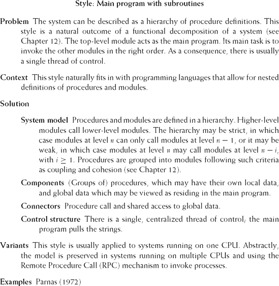
Figure 11.6. Main-program-with-subroutines architectural style (Source: M. Shaw, Some Patterns for Software Architectures, in (Vlissides et al., 1996, pp. 255–269). Reproduced by permission of M. Shaw.)
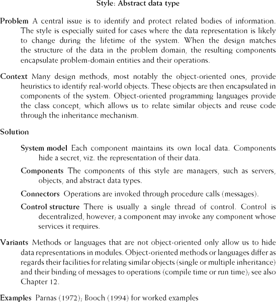
Figure 11.7. Abstract-data-type architectural style (Source: M. Shaw, Some Patterns for Software Architectures, in (Vlissides et al., 1996, pp. 255–269). Reproduced by permission of M. Shaw.)
The repository style fits situations where the main issue is to manage a richly structured body of information. In our library example in Chapter 9, the data concerns things such as the stock of available books and the collection of members of the library. This data is persistent and it is important that it always reflects the true state of affairs. A natural approach to this problem is to devise database schemas for the various types of data in the application (books, journals, library clients, reservations, and so on) and store the data in one or more databases. The functionality of the system is incorporated in a number of, relatively independent, computational elements. The result is a repository architectural style.
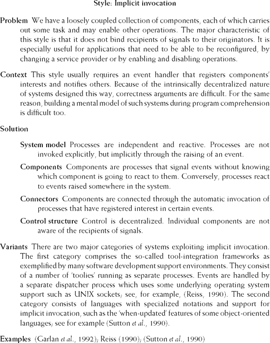
Figure 11.8. Implicit-invocation architectural style (Source: M. Shaw, Some Patterns for Software Architectures, in (Vlissides et al., 1996, pp. 255–269). Reproduced by permission of M. Shaw.)
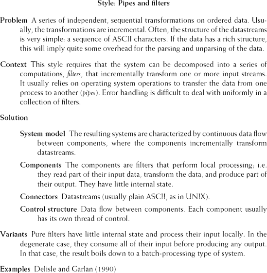
Figure 11.9. Pipes-and-filters architectural style (Source: M. Shaw, Some Patterns for Software Architectures, in (Vlissides et al., 1996, pp. 255–269). Reproduced by permission of M. Shaw.)
Modern compilers are often structured in a similar way. Such a compiler maintains a central representation of the program to be translated. A rudimentary version of that representation results from the first, lexical, phase: a sequence of tokens rather than a sequence of character glyphs. Subsequent phases, such as syntax and semantic analysis, further enrich this structure into, for example, an abstract syntax tree. In the end, code is generated from this representation. Other tools, such as symbolic debuggers, pretty-printing programs, or static analysis tools, may also employ the internal representation built by the compiler. The resulting architectural style again is that of a repository: one memory component and a number of computational elements that act on the repository. Unlike the database variant, the order of invocation of the elements matters in the case of a compiler. Also, different computational elements enrich the internal representation, rather than merely update it.
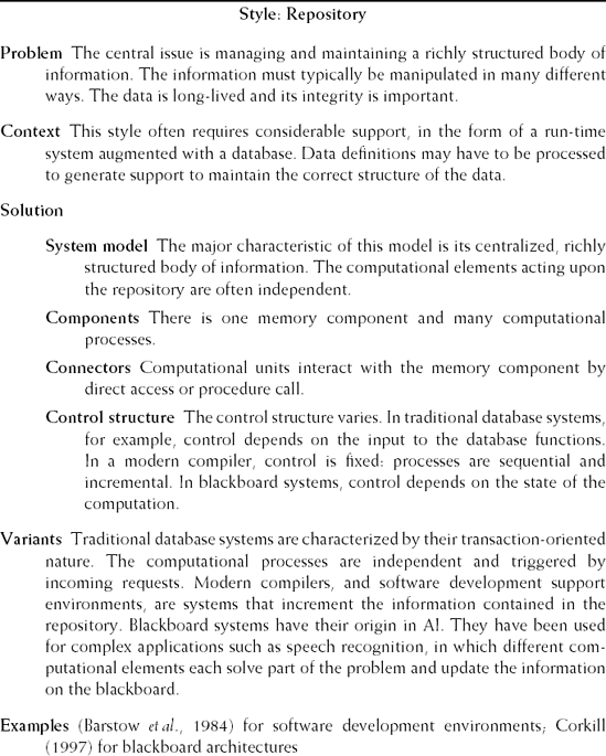
Figure 11.10. Repository architectural style (Source: M. Shaw, Some Patterns for Software Architectures, in (Vlissides et al., 1996, pp. 255–269). Reproduced by permission of M. Shaw.)
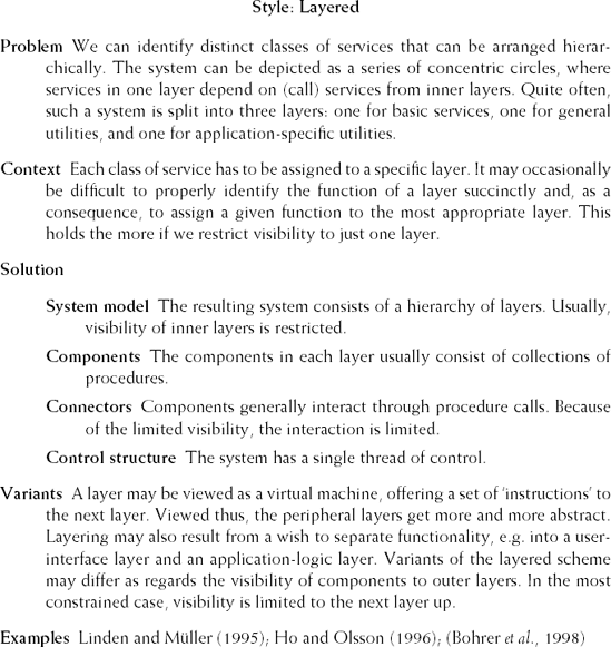
Figure 11.11. Layered architectural style (Source: M. Shaw, Some Patterns for Software Architectures, in (Vlissides et al., 1996, pp. 255–269). Reproduced by permission of M. Shaw.)
The repository architectural style can also be found in certain AI applications. In computationally complex applications, such as speech recognition, an internal representation is built and acted upon by different computational elements. For example, one computational element may filter noise, another one builds up phonemes, etc. The internal representation in this type of system is called a blackboard and the architecture is sometimes referred to as a blackboard architecture. A major difference with traditional database systems is that the invocation of computational elements in a blackboard architecture is triggered by the current state of the blackboard, rather than by (external) inputs. Elements from a blackboard architecture enrich and refine the state representation until a solution to the problem is found.
Our final example of an architectural style is the layered architectural style. A prototypical instance is the ISO Open System Interconnection Model for network communication. It has seven layers: physical, data, network, transport, session, presentation, and application. The bottom layer provides basic functionality. Higher layers use the functionality of lower layers. The different layers can be viewed as virtual machines whose 'instructions' become more powerful and abstract as we go from lower layers to higher layers.
In a layered scheme, by definition, lower levels cannot use the functionality offered by higher levels. The other way round, the situation is more varied. We may choose to allow layer n to use the functionality of each layer m, with m < n. We may also choose to limit the visibility of functionality offered by each layer and, for example, restrict layer n to use only the functionality offered by layer n — 1. A design issue in each case is how to assign functionality to the different layers of the architecture, i.e. how to characterize the virtual machine it embodies. If visibility is not restricted, some of the elegance of the layered architecture gets lost. This situation resembles that of programming languages containing low-level, bit-manipulation operations alongside whilestatements and procedure calls. If visibility is restricted, we may end up copying functionality to higher levels without increasing the level of abstraction.
Linden and Müller (1995) give an example of a layered architectural style for use in telecommunications. In this example, layers do not correspond to different levels of abstraction. Rather, the functionality of the system has been separated. Two main guidelines drive the assignment of functionality to layers in this architecture:
Hardware-dependent functionality should be placed in lower layers than application-dependent functionality.
Generic functionality should be placed in lower layers than specific functionality.
The resulting architecture has four layers:
Operating system This layer comprises the run-time system, database, memory management, and so on.
Equipment maintenance This layer houses the control for peripheral devices and its interconnection structure. It deals with such things as data distribution and fault-handling of peripheral hardware. The bottom two layers together constitute the distributed operating infrastructure upon which applications run.
Logical-resource management Logical resources come in two flavors. The first class contains abstractions from hardware objects. The second class consists of software-related logical objects, such as those for call-forwarding in telephony.
Service management This layer contains the application functionality.
A similar line of thought can be followed in other domains. For instance, it is hard to predict how future household electronic equipment will be assembled into hardware boxes. Will the PC and the television be in the same box? Will the television and the DVD player be combined or will they remain as separate boxes? No one seems to know. Since the life of many of these products is about six months, industry is forced to use a building-block approach, emphasizing reuse and the development of product families rather than products. A division of functionality into a hardware-related inner layer, a generic signal processing layer, and a user-oriented service layer suggests itself. The above architecture for telecommunications applications can be understood along the same lines.
In practice, we usually encounter a mixture of architectural styles. For example, many software development environments can be characterized as a combination of the repository and layered architectural styles; see also Chapter 15. The core of the system is a repository in which the various objects, ranging from program texts to work-breakdown structures, reside. Access to these objects as well as basic mechanisms for the execution and communication of tools are contained in a layer on top of this repository. The tools themselves are configured in one or more layers on top of these basic layers. Interaction between tools may yet follow another paradigm, such as implicit invocation.
The software architecture captures early design decisions. Since these early decisions have a large impact, it is important to start testing even at this early stage. Testing software architectures is commonly referred to as software architecture assessment: the software architecture is assessed with respect to quality attributes such as maintainability, flexibility, and so on.
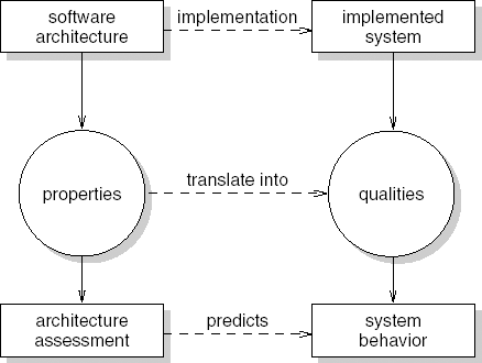
It is important to keep in mind that in this process the architecture is assessed, while one hopes the results will hold for a system yet to be built. As a result, conclusions will often be at quite a general level. Also, there is some uncertainty about whether these results will actually be realized. Suppose the architecture is assessed for maintainability. Even if the outcome is quite positive, a sloppy implementation process may yet spoil the rosy picture. Figure 11.12 illustrates this issue. Architecture assessment takes place at the left-hand side of the figure, while one assumes the results will be valid for the right-hand side.
There are two broad classes of techniques for evaluating a software architecture. The first class comprises measuring techniques that rely on quantitative information. Examples include architecture metrics and simulation. The second class comprises questioning techniques, in which one investigates how the architecture reacts to certain situations. This is often done with the help of scenarios. In the following text, we concentrate on the latter.
There are different types of scenario one may use in architecture assessments. Common types are:
Use cases: these are often already available or can be derived from the requirements.
Change cases: change cases describe possible or likely future situations. They describe 'what if' situations, such as 'what if our library has to be able to handle DVDs as well as books and journals?'.
Stress situations: these describe extreme conditions under which the system has to operate, such as limits with respect to performance or the number of concurrent users of the system.
Far-into-the-future scenarios: these are like change cases, but farther away. For instance, we may envision a future in which a library changes from a document archive to a memory archive. We may want to retain how an old-fashioned bakery smells or the sound of an Amsterdam tram.
One of the best known architecture assessment methods is the Architecture Tradeoff Analysis Method (ATAM). As the name says, an important goal of ATAM is to determine how quality attributes interact. If we decide to include an authorization component to increase security, it is likely to degrade performance. By making the consequences of design decisions explicit, it becomes possible for stakeholders to trade off the different possibilities and make informed decisions, with clear insight into the consequences thereof.
The main steps of ATAM are listed in Table 11.8. There may be a preparatory phase in which participants meet to discuss the whole exercise, and a follow-up phase at the end in which a written res port is delivered. The early steps are meant to make the participants familiar with the major quality drivers for the system (step 2), the solution chosen (step 3), and the approaches and patterns used in this solution (step 4). In step 5, the quality requirements are articulated in more detail. The project's decision makers are key in this process. The end result of this exercise is a tree. The root node is termed 'utility'. It expresses the overall quality of the architecture. The next level contains the quality attributes that will be evaluated. These are again broken down into more detailed constituents. The leaf nodes are concrete scenarios. Figure 11.13 gives part of a possible utility tree for assessing our library system.
Table 11.8. Steps of ATAM
|
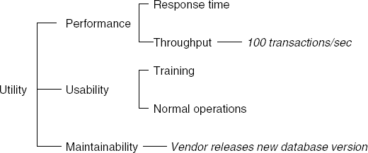
The leaf nodes in Figure 11.13 are printed in italic. This description is incomplete. The full representation has to contain more information, for example the type of information contained in a quality attribute scenario (see Section 6.3).
A complete utility tree may contain more scenarios than can be analyzed during the assessment. It is then useful to prioritize scenarios. ATAM suggests two criteria for doing so. Using the first criterion, the stakeholders indicate how important the scenarios are (e.g. using a simple three-point scale: High, Medium, Low). Using the second criterion, the architect ranks the scenarios according to how difficult he believes it will be to satisfy the scenario, using the same three-point scale. In the remainder of the assessment, one may then, for instance, concentrate on the scenarios that score High on both scales.
In step 6, the scenarios are discussed one at a time. For each scenario, the architect walks the stakeholders through the architecture, explaining how the architecture supports that scenario. This may trigger a further discussion of the architectural approaches chosen. The end result is a documented list of sensitivity points, tradeoff points, risks, and nonrisks, relating the architectural decisions made to the relevant quality attributes.
A sensitivity point is a property of the architecture that is critical for a certain quality attribute. For example, the possibility of undoing user actions critically affects the usability of our library system, and this property therefore is a sensitivity point with respect to usability. At the same time, this decision also is a sensitivity point with respect to performance. If a decision is a sensitivity point for more than one quality attribute, it is called a tradeoff point. If performance is of utmost importance, the decision to include an undo facility may be a risk. If this decision is not critical, it is a nonrisk.
The utility tree is based on the main drivers used during the design of the architecture. Its construction is done in consultation with the main decision makers. There are other stakeholders, such as a maintenance manager or security expert, that can also be polled for additional scenarios. This is done in step 7. In a similar way to step 5, these scenarios are prioritized and a selection is made for further study. In a similar way to step 6, these additional scenarios are analyzed in step 8. Finally, the collected information is summarized and presented to all stakeholders in step 9.
The result of an architecture assessment goes way beyond a list of sensitivity points, tradeoff points, risks, and nonrisks. Stakeholders, including the architect, often construct a much deeper understanding of the architecture, its underlying decisions, and the ramifications thereof. Also, better documentation is often delivered as a byproduct of the assessment. This is similar to the extra benefits of software inspections and walkthroughs besides the identification of software errors (see Section 13.4.2).
In practice, organizations often perform software architecture assessments in a less rigid sense than suggested by the above description of ATAM. Usually, a cafeteria-like approach is followed, whereby elements from ATAM and similar methods are chosen that best fit the situation at hand (Kazman et al., 2006).
Software architecture is concerned with the description of elements from which systems are built, the interaction among those elements, patterns that guide their composition, and constraints on those patterns. The design of a software architecture is driven by quality concerns. The resulting software architecture is described in different views, each of which addresses specific concerns on behalf of specific stakeholders. This resembles the way different drawings of a building emphasize different aspects on behalf of its different stakeholders.
It is important to document not only the resulting solution but also the decisions that led to that solution, its rationale, and other information that is helpful to guide its further evolution.
Software architecture is an important notion, for more than one reason:
The comparison with traditional architecture reveals commonalities which help us to get a better grip on the software design process and its products. Software architecture is not only concerned with the blueprint that is the outcome of the design process. The notion of an architectural style has merits of its own and the relationship between style on the one hand and engineering and materials on the other hand provide additional insights into what software design entails (Perry and Wolf, 1992).
The field may eventually yield a repertoire of concepts that software architects can use in their search for solutions. Expert designers in any field build on a vast collection of reusable concepts. These concepts are given unique names, which are used to communicate them, and serve as labels when retrieving and storing them in human memory. Software architecture is concerned with identifying, describing and categorizing components at a high level of abstraction. The resulting abstractions are to become part of the vocabulary of software engineers, much as abstract data types are already part of that vocabulary.
Phrasing a software design in software architectural terms promotes consistency during development and maintenance. Phrasing the global design in terms of an architecture forces us to think about its general flavor, in terms of types of component and connector, as well as a certain control structure. By making this intuition explicit, it both describes and prescribes how the system should look and how it may evolve over time.
A software architecture captures early design decisions. The architecture can be used to evaluate those decisions. It also provides a way to discuss those decisions and their ramifications with the various stakeholders.
Shaw and Garlan (1996) is an early influential source that discusses the emerging field of software architecture, in particular software architectural styles. (Bass et al., 2003) give a broad overview of the field, including the various forces that influence software architecture and the purposes of a software architecture, and ADD. It includes a number of case studies to illustrate these issues. (Clements et al., 2003) is wholly devoted to architecture documentation and architectural views. The state of the art in software architecture is reflected in (Software, 2006b). A comparison between the classical field of architecture and software architecture is made in (Perry and Wolf, 1992). Different architectural views of the same system are the topic of (Kruchten, 1995) and (Soni et al., 1995). Rozanski and Woods (2005) give a very good catalog of useful architectural viewpoints. Architecture as a set of design decisions is the topic of (Tyree and Akerman, 2005). Architectural mismatches as a consequence of implicit assumptions are discussed in (Garlan et al., 1995).
Software architecture and design patterns have been strongly influenced by the works of the architect Christopher Alexander. It is certainly worthwhile to have a look at (Alexander et al., 1977) and (Alexander, 1979). Lea (1994) gives an introduction to his work for software engineers. Alexander (1999) explains the origins of pattern theory. (Buschmann et al., 1996) is an excellent source for architectural patterns. The theory of programming plans stems from (Soloway, 1986).
(Clements et al., 2002) discuss software architecture evaluation in great depth. (Maranzano et al., 2005) discuss experiences with architecture reviews. A survey of architecture assessment methods is given in (Dobrica and Niemelä, 2002).
Many issues related to software architecture have not been touched upon in this chapter. These include efforts to classify software architectural styles along different dimensions (Shaw and Clements, 1996), architecture description languages and supporting tools (Shaw et al., 1995), architecture description languages (Medvidovic and Taylor, 2000), architecture reconstruction (Deursen et al., 2004), and the role of the software architect (Kruchten, 1999), (Mustapic et al., 2004).
Give a definition of the term 'software architecture'. Explain the different elements in this definition.
What is the difference between software architecture and top-level design?
What is the main purpose of a software architecture?
What is the relation between design decisions and software architecture?
Explain the architecture design method called Attribute-Driven Design (ADD).
What is the role of the backlog in design?
What is the difference between the notions of software architecture and design pattern?
What is the difference between the conceptual or logical viewpoint and the implementation viewpoint?
Explain the difference between module, component-and-connector, and allocation viewpoints.
Describe in your own words the essence of the implicit-invocation architectural style.
In what sense does the abstract-data-type architectural style constrain the designer?
Why is error-handling difficult in the pipes-and-filter architectural style?
Why is language so important in software design?
Define the following component types: computational, memory, and manager.
Define the following connector types: data flow, message passing, and shared data.
In what sense may the layers in a layered architecture be viewed as virtual machines?
What is a software architecture assessment?
Explain the steps of ATAM.


[10] We use the terminology from RUP (Kruchten, 2003). In (Kruchten, 1995), slightly different terminology is used.
[11] This business view was created by Cuno de Boer, Raymond Backus, Youri op 't Roodt, and Reinier L'Abée, students in my 2005 Software Architecture course.
[12] Here, we may note another similarity between classical architecture and software architecture. In the 1950s and 1960s, housing was a major problem in Western Europe and beyond. There were far too few houses available, most of those were of a bad quality (damp, no bathroom, too small). In the post-war economic boom, many suburbs were constructed with lots of spacious apartments, each one a container made of steel and concrete. These new suburbs solved one problem–the housing of a large number of people — but at the same time created other problems which only showed themselves much later, e.g. lack of community feeling and social ties, high crime rates. As a result, massive renovation projects have started and many a high-rise apartment building has been demolished.
In software development, we developed company-wide systems in the 1970s and 1980s with an emphasis on performance, uniformity, and standardized ways of working. Many of these systems are unable to cope satisfactorily with today's requirements of flexibility and adaptability, and are therefore being renovated.
[13] These notions of component and connector are not related to the component-and-connector viewpoints discussed in Section 11.3.