
With Michel Chaudron, Technische Universiteit Eindhoven, The Netherlands, and Ivica Crnkovic, Mälardalen University, Sweden
LEARNING OBJECTIVES
To understand the essentials of component-based software engineering
To know the main characteristics of components and component models
To be aware of software development processes for component-based systems
To be aware of the mutual relations between software architecture and component models
Note
In component-based software engineering (CBSE), systems are assembled from existing components. In CBSE, there are independent development processes for components and for systems built out of components. Composing a system out of components is only possible if those components conform to the same set of standards, also known as their component model. Component models differ in the way they handle quality properties. Component models influence software architecture, and vice versa.
Chapter 17 gave a general discussion of software reuse. In this chapter, we focus on a specific type of reuse, that of components. A component is a building block for software, much like an LCD screen is a building block for a mobile phone and a rubber tire is a building block for a car. The idea behind component-based software engineering (CBSE) is to assemble systems out of existing, independently developed, components. CBSE entails more than the mere reuse of components, though. It also aims to increase the flexibility of systems through improved modularization.
The idea of separating the manufacturing of parts and the assemblage of those parts into a product was pioneered around 1800 in the production of rifles. This idea has fundamentally changed the hardware-manufacturing business. In this chapter, we discuss how to apply the same idea to the production of software. The production of software parts – the components – is separated from the assemblage of those parts into applications. As a consequence, there will be two separate development processes, one for components and one for applications. These processes are not independent. Applications need certain components and components had better be used in applications. So there are dependencies between the two development processes. These development processes and their dependencies are discussed in Section 18.3.
LEGO is often taken as an example of a component-based approach. LEGO is a set of building blocks in a large variety of shapes and colors. LEGO is sold in boxes that contain a number of blocks that can be composed to make up toys such as cars, trains or airplanes. In order to enable their composition, all LEGO blocks provide small cylindrical stubs on the top and complementary holes on the bottom of the shape. The conformance of the blocks to this convention ensures that blocks, possibly from different LEGO boxes, can be combined. Moreover, they can be combined into constructions other than the construction suggested by the manufacturer. Hence, LEGO blocks have the characteristic that they are easily composable and are generic. These are characteristics that we also look for in software components.
There are however, many more toys that consist of building blocks that can be assembled. Take, for example, Meccano and traditional jigsaw puzzles. While each of these can be combined with blocks of the same type (Meccano–Meccano, LEGO–LEGO, etc.), they cannot be combined with blocks of another type (e.g. Meccano–LEGO). This illustrates that composability of building blocks is related to the conformance to a set of conventions. This set of conventions is called a component model. Component models and components are discussed in Section 18.2.
Components are to become parts of bigger systems. As such, they have to fit the architecture of those systems. One possibility is to first design the architecture and then search for components that fit the architecture. A second possibility is to design an architecture of a family of (similar) systems and develop components that fit a variety of products within that family. A third possibility is to use a bottom-up approach in which the architecture is made to fit the available components. These different architectural approaches are discussed in Section 18.4.
A warning about terminology is warranted. In CBSE, the word 'component' has a more specific meaning than its meaning in Standard English. Whereas 'component' in general means 'part', in CBSE a 'component' is 'a piece of software that conforms to the rules of a particular software component model'. The component model used in one system may be very different from that used in another system. As a result, the notion of component differs between different types of domain. In the literature, the component model assumed is often implicit. Furthermore, in earlier chapters of this book we used the term 'component' in its general sense of 'part' or 'constituent'.
CBSE is not a goal in itself, but a means to an end. CBSE is aimed at contributing to the realization of the business goals of an organization. The main motivations for applying CBSE are the topic of Section 18.1.
It is not the strongest of the species that survive, nor the most intelligent, but the ones most responsive to change.
Charles Darwin
CBSE contributes to the following business goals:
CBSE increases the quality of software, especially its evolvability and maintainability. This holds for both the quality of individual components and for the quality of the architecture of systems built in a component-based way.
CBSE increases the productivity of software development (more software per dollar).
CBSE shortens the development time, and thus time to market, of software.
We explain these benefits in a bit more detail.
CBSE leads to a higher quality of individual software components in the following ways:
CBSE requires us to make the dependencies of components explicit. This reduces programming errors that occur as a result of unknown or undocumented dependencies. Also, testing can be performed more effectively if dependencies are explicit.
The more often a component is (re)used, the more likely it is that errors are found and removed. Errors may be uncovered during execution of a component or through the testing that is done before a component is integrated into a system.
Before components are offered to other parties on a commercial basis, they must be tested thoroughly. Otherwise, the company that offers this component will lose its credibility and go out of business quickly.
Components must be well-documented, otherwise parties other than the creator of the component have great difficulty in using the component.
Developing software in a component-based way requires a discipline of strict modularization. The strict modularization limits the domino effect of changes in the system. Hence, the effort needed to change a component-based system is likely to be less than the effort needed when the same changes are made to a system that is not modularized according to a component-based design discipline. This property improves maintainability. When subsystems are strictly modularized, it becomes easier to change parts to support new features. This improves the ability of the system to evolve.
CBSE increases productivity through the reuse of building blocks that have been developed in earlier efforts or by other parties. In order for this to enhance productivity, the acquisition and integration of a component should of course be cheaper than developing that component from scratch. This general characteristic of software reuse has been discussed in Chapter 17.
The size of professional software systems is in the order of millions of lines of code. The time needed to realize such software systems may span several years. CBSE contributes to reducing the development time of software by using existing components rather than developing components from scratch. Another way in which CBSE may reduce development time is by enabling concurrent development of components. Concurrent development of components is easier if components have minimal mutual dependencies, i.e. when components are loosely coupled. Any dependencies that do exist between components must be specified explicitly. Hence, in CBSE, components are designed and specified in such a way that they can be constructed independently of, and concurrently with, other components.
In the introduction to this chapter, we made an analogy with LEGO and Meccano and noticed that composing building blocks is feasible only if they conform to the same set of conventions.
In the world of engineering, the conventions for components are chosen such that they can be used for constructing systems with certain properties. For example, a racing car requires parts that are lightweight and aerodynamic in order to obtain an overall system that is fast. An army tank requires parts that are tough in order to make a robust system.
Software components encapsulate functionality in a form that conforms to a set of conventions. These conventions ensure composability and determine the properties of systems that can be built using a particular type of components. Rather than physical properties, such as weight and shape, software components are required to have properties such as computational efficiency, resource efficiency, and reliability. These characteristics are captured in the following definition.
A component model defines standards for:
properties that individual components must satisfy, and
methods, and possibly mechanisms, for composing components.
Informally, a component model defines the types of building block and the recipe for putting these building blocks together. This definition stresses a generic constraint: components are composable.
A component is a building block that conforms to a component model
The key aspect of this definition is composability. For software, composability may be achieved by using explicit interfaces for defining what is offered as well as what is required by a piece of software and by defining the manner in which a component can communicate with other pieces of software. Whereas composability is a necessary technical requirement, genericity is a desirable requirement from a business perspective. A generic component can be used more often and hence has greater potential for generating revenue. The genericity characteristic implies certain technical characteristics. For instance, components with lower coupling generally have fewer dependencies on their environment and, hence, can be applied in a wider context. The following definition of a component is more specific to software.
A software component:
implements some functionality,
has explicit dependencies through provided and required interfaces,
communicates through its interfaces only, and
has a structure and behavior which conform to an encompassing software component model; notably, this applies to the interfaces and patterns of communication of the component.
Whereas a component model defines a standard, a component technology is the collection of implementation artifacts that realize this standard.
A software component technology is the implementation of a component model by means of:
standards and guidelines for the implementation and execution of software components, and
executable software that supports the implementation, assembly, deployment, and execution of components.
There are many examples of software component technologies. A large number of component models is oriented towards business information systems. These include Enterprise JavaBeans (EJB) (Burke and Monson-Haefel, 2006), COM+ (Box, 1997), .NET (Chappell, 2006), and the CORBA-Component Model (CCM). Other component models are oriented towards embedded systems: the Robocop component model (Muskens et al., 2005) for consumer electronics and the SaveCCM (Åkerholm et al., 2007) for automotive systems. Each of these technologies embodies some underlying component model. Let's look at the .NET component technology as an example. Implementation support for .NET is provided by the Visual Studio .NET toolset which includes dedicated editors and compilers. Run-time support is provided by a run-time execution platform (called the common language run-time, CLR) that runs on top of the regular operating system.
The composability requirement for components entails the standardization of interfaces and interaction. These conditions may be sufficient to ensure composability at the implementation level of the component. However, much more can be said about properties that are generally desired from software components, such as component granularity, encapsulation, cohesion, or testability. These additional properties are related to general aspects of the design and development of components and are discussed in Chapter 12.
Although the definition of a component model allows a lot of freedom, in practice there is a lot of commonality amongst component models. Comparing component technologies shows that they standardize conventions that cover multiple stages of the development of components. In the next subsection we discuss how the standards defined by component models are related to different development stages of a component.
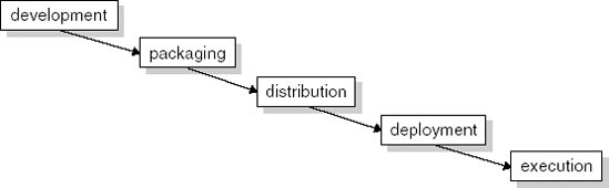
When we look at the life cycle of a component, it passes through the following global stages, depicted in Figure 18.1: development, packaging, distribution, deployment, and execution. In the development stage, the design, specification, implementation, and meta data of components is constructed. In the packaging stage, all information that is needed for trading and deployment of the component implementation is grouped into a single package. The distribution stage deals with searching, retrieval, and transportation of components. The deployment stage addresses issues related to the integration of component implementations in an executable system on some target platform. Finally, the execution stage deals with executing and possibly upgrading components.
Across these different stages of their life cycle, components are represented in different forms. In the development stage, components may be represented by means of a design or specification language, such as a set of UML diagrams, and as a set of source-code and configuration files, such as a directory with .c and .h files for C or a set of class files in case of Java, that together can be turned into executable code. In the packaging stage, the files that together form a component are bundled into a single unit, for example in a compressed file. In the distribution stage, packaged components are represented in a format that can be transmitted across a network or stored on some physical carrier such as a disk or memory stick. This may be standardized by a component model but, in general, distribution formats are from the area of distributed systems – nowadays, mostly Internet standards. At the deployment stage, components are unpackaged in a form that can be installed onto a target machine. In the execution stage, components take the form of blocks of code and data in the memory of a processor and cause a set of actions on this processor. All these forms are different views on, or manifestations of, what is logically a single building block.
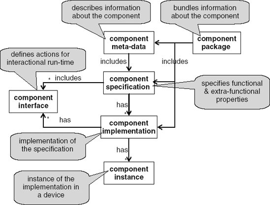
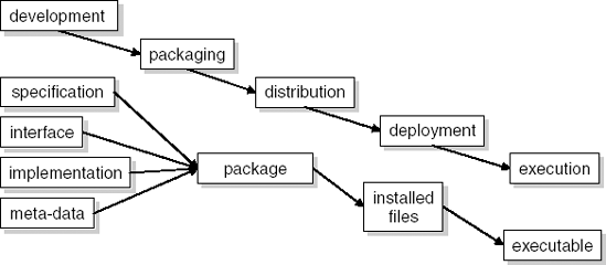
Cheesman and Daniels (2000) introduce convenient terminology for denoting the different forms of components. Figure 18.2 shows the distinction between different forms of components that they introduced and the relations between them. Figure 18.3 shows how these different forms relate to different stages of development.
The component specification describes properties that are, or should be, realized by the corresponding component implementation. Many different properties may be included in a specification. A component specification typically includes the following important properties:
functionality (what a component does),
behavior (the order of actions a component performs),
interaction potential (the ways according to which a component can interact with other software),
quality properties such as performance and reliability.
Of course, these properties should be specified in a complete, precise, and verifiable way.
The interface of a component is defined in the design stage and continues to play an important role in execution time. A component interface defines the actions through which components may communicate with each other. Interfaces are offered by one component in order to be used by other components. The component that offers an interface is responsible for realizing the actions of the interface. The component that uses the actions of an interface only needs to know what the action achieves, not how it is achieved. In this sense, users of an interface are shielded from the machinery that is used to implement it. This shielding is a means of abstraction – details about the realization are omitted. As a result of this abstraction, different implementations of an interface may be used to realize some action without users of the interface being aware of it. This is, of course, the basic idea of information hiding, as discussed in Chapter 12.
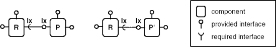
A typical use of this property of interfaces is to replace a component by a newer version (see Figure 18.4). This figure shows that component P can be replaced by component P'if P'realizes the same interface Ix. Component Rthat uses interface Ixneed not be changed. The component that offers an interface is called the provider of that interface; the component that uses the interface is called the requirer of the interface.
The purpose and scope of a component specification differ from the purpose and scope of a component interface. The most important difference is that specifications define a realization contract, while interfaces describe usage contracts. During development of a component, the specification is a prescription of what the implementation should realize. As such, the specification may include the definition of interfaces. Once the implementation of a component is finished, a specification describes what architects and developers who wish to use a component may want to know about it. Here, the specification is used to understand the component.
A component specification and an interface also differ in scope: if a component has multiple interfaces, these are all listed as part of the specification. The scope of a specification is the component as a whole. As such it needs to specify the way in which the interfaces of a component relate to each other.
A component implementation is a realization of a component specification. There has been some discussion on how strict the hiding of internals of components should be. The black-box requirement for components has been criticized as being too strong a constraint. For the purpose of tailorability or testability, components should disclose more of their internals. Several variants of black box have been proposed; they differ in the degree to which the internals of components can be inspected and changed by parties other than its developer:
Black-box component: only the specification and the contract of the component are available to the user or integrator of a component.
Glass-box component: the internals of the component may be inspected but not modified. The implementation can thus add information to the specification of the component.
Grey-box component: part of the internals of a component may be inspected and limited extension or modification is possible; e.g. only certain methods may be defined or redefined by the user or integrator.
White-box: the component is open to both inspection and modification by its user or integrator.
A component package is a unit of distribution. A package contains the implementation of a component, relevant data files, meta-data about the component, and meta data about the package. The meta-data of a package contains a table of contents of the files in the package. It may be compressed to improve download time, and encrypted and certified to improve security. It can be compared to the way a ZIP file can be used to package a collection of files into a single unit.
Finally, the component instance consists of the executable code and associated data in the target machine. The relation between a component implementation and a component instance is like the relation between a class and an object. The component instance will form part of the execution architecture of the running system. The execution architecture determines the performance of a system by defining the mapping of functionality onto run-time entities (such as processes and resources) in a system. The component instance has to conform to conventions that are dictated for this purpose by the software architecture.
Since the mid 1990s, software architecture has been recognized as an important intermediate artifact of software engineering projects. The goal of a software architecture is to define the key principles and guidelines for developing a software system such that the resulting system and process meets its functional and quality requirements (see Chapter 11).
The functional requirements can be achieved by defining a functional decomposition of a system. Functionality behaves relatively nicely in an additive manner: to increase the functionality of a system, we just add a new subsystem. Achieving the quality properties of a system is often more difficult. One complicating factor is that quality properties do not have the additive property, but are the collective result of interaction by all parts of a system. The performance of a system is not 'handled' by one component; it is 'everywhere'. In order to achieve some set of quality properties, all parts of a system must adhere to certain principles. Since quality is to a large extent determined by the software architecture (see Chapter 11), component-based software engineering requires that attention be paid to the software architecture.
To successfully develop systems in a component-based manner, an architectural plan needs to be in place that organizes how components fit together and how, once assembled, a system meets its quality requirements. In an ideal case, the development of a system is driven by an architecture that is developed up front. Based on this architecture, a component model is selected or a dedicated component model is developed such that the rules of the component model match those of the architecture. Examples of dedicated component models are the Koala model (Ommering et al., 2000) developed for meeting resource constraints in consumer devices, and the SaveCCM (Åkerholm et al., 2007) model developed for meeting dependability requirements in the automotive domain. As these examples illustrate, dedicated component models are developed in domains that have rather specific quality requirements.
Developing a proprietary component model takes a lot of effort. Therefore, a practical alternative is to select the architecture and component model in concert. To this end, a set of candidate architectures and a set of candidate component models are selected. The choice of a particular component model limits the possible architectures that can be realized. If a component model is not an ideal match with the target architecture, then some additional work is needed to provide extra features or eliminate (or hide) superfluous features. So, an architecture constrains the possible component models and a component model constrains the possible architectures. Typical issues that are the subject of architectural decisions which may influence the choice between a custom architecture and custom component model versus a commercial component model are: security mechanisms, transaction mechanisms, and scheduling policies. Typically, policies for such issues are hard-wired into commercial component models, but can be tailored when designing a custom component model.
There are different approaches to dividing the responsibility for managing quality properties between components and the execution platform. The different types of approach are characterized by the reference architectures shown in Figure 18.5. The grey areas in this figure denote the locations where logic resides that handles quality properties of the system. These reference architectures talk about quality properties in general. An instance of the architecture could be concerned with performance, security, reliability. There are two main dimensions in which these approaches differ in managing quality properties:
The party that manages the property: Either the property is endogenous (that is, it is handled by the component) or it is exogenous (that is, it is handled by the system).
The scope of management of the property: A property is managed on a percollaboration basis or on a system-wide scale.
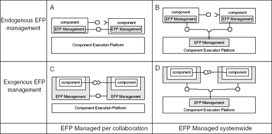
Many component models provide no specific facilities for managing quality properties. The way a property is handled is, in that case, left to the designers of the system; as a result, a property may not be managed at all (approach A, in Figure 18.5). This approach makes it possible to include policies for managing quality properties that are optimized towards a specific system and can also cater for adopting multiple policies in one system. This heterogeneity may be particularly useful when commercial off-the-shelf (COTS) components need to be integrated. On the other hand, the fact that such policies are not standardized may be a source of architectural mismatch between components.
The compatibility of components can be improved if the component model provides standardized facilities for managing quality properties (approach B in Figure 18.5). In this approach, there is a mechanism in the component execution platform that contains policies for managing quality properties for individual components as well as for quality properties involving multiple components. The ability to negotiate the manner in which quality properties are handled requires that the components themselves have some knowledge about how the quality properties affect their functioning. This is a form of reflection.
A third approach is that the components should be designed such that they address only functional aspects and no quality properties. Consequently, in the execution environment these components are surrounded by a container. This container contains the knowledge on how to manage quality properties. Containers can either be connected to containers of other components (approach C in Figure 18.5) or they can interact with a mechanism in the component execution platform that manages quality properties on a system-wide scale (approach D in Figure 18.5). Approach C manages interaction between two components. In approach D, the scope of the management can be global across the system.
The container approach is a way of realizing separation of concerns in which components concentrate on functional aspects and containers concentrate on quality aspects. In this way, components become more generic because no modification is required to integrate them into systems that may employ different policies for managing quality properties. Since in this approach components do not address quality properties, they are simpler and smaller, and hence cheaper to implement or integrate.
As well as the differences discussed above, component models also have a number of features in common. An overview of these common features is given in Table 18.1. The features common to component models are:
Table 18.1. Common features of component models
Infrastructure |
Instantiation |
Binding |
Communication |
Discovery |
Announcement of capabilities |
Component and application development support |
Language independence |
Platform independence |
Analysis support |
Support for upgrading and extension |
Support for quality properties |
Infrastructure All component models provide an infrastructure: mechanisms for component instantiation, binding, communication, distribution of components over hardware, announcing capabilities of components and discovery of desired components. These mechanisms are needed to create a composition of components that can cooperate in performing a certain task.
Instantiation A component instance is the instantiation of an executable component at a specific location in the memory of a device. The relation between a component instance and a component implementation is the same as that between an object and a class. Once in operation, each component instance may create and manage its own data structures. There are a number of different ways in which the instantiation can be achieved. The distinguishing factor is the element in the architecture that controls the instantiation. In existing component models, instantiation is typically controlled by the component infrastructure, a component container, or a component factory.
Binding In the context of component-based systems, binding is the creation of a link between two or more component instances. Binding can be done at design-time, compile-time or run-time. At design time and compile time, the binding is done by the developer. These types of binding are called early binding. Run-time binding is also called late binding, or dynamic binding, since each invocation may, in principle, be to another instance of the component. The link between component instances may be used for communication and navigation. The distinguishing aspect of the different ways in which binding can be organized in a component model is the party that initiates the binding.
We distinguish first-party binding and third-party binding. In first-party binding, a component instance binds itself to another component. In third-party binding, a binding between component instances is created by a party other than those being bound. Consider the scenario where a binding is constructed between component A and component B. In first-party binding, component A asks a registry where to find component B and the registry provides A with a reference to B; A knows about the component which it wishes to collaborate. In third-party binding, another party, say C, manages the binding between A and B. C can connect A to B and acts as a controller; components A and B act as slaves to the controller.
Communication To facilitate communication between components, a component infrastructure must provide some interaction mechanisms. The interaction styles supported are partially defined by the architectural styles that the component model supports. The communication styles that a component infrastructure supports determine a number of the quality properties that systems built using these components can obtain. For instance, some communication styles favor efficiency over flexibility. The most common style is request–response as implemented by method-calling. This style is the basis of all imperative programming languages and does not require any special facilities from the component infrastructure. The next most common style is events. The event style is often used in combination with request–response. It is typically used for notification, e.g. of exceptions. The publish–subscribe style of communication can be seen as a generalization of the event style to distributed systems. Streaming is often used in systems that are aimed at multimedia processing.
Discovery A component model needs to define a mechanism by which components in the system can be discovered. A discovery mechanism is needed to support dynamic binding. Discovery mechanisms are most prominent in component models with run-time binding. In systems with design-time or compile-time binding, the discovery is typically guided by the designer or developer. In systems with runtime binding, a registry is commonly used for the discovery of components. Dynamic binding is a main characteristic of service-oriented architectures; see also Chapter 19.
Announcement of capabilities Usually the capabilities of a component are expressed by the interfaces that it implements. The way in which interfaces are specified differs between component models. Some component models introduce a special language for expressing interfaces; others use programming languages to specify the interfaces.
Component and application development support Component models have a variety development features. For example, COM and .NET support development of components independent of programming language, whereas Enterprise Java-Beans (EJB) supports platform independence.
Language independence Some component models support development of components in different programming languages. In order to achieve interoperability between the components developed in different programming languages, the interfaces must be specified independent of the programming language. Usually an interface description language (IDL) is used for this purpose.
Platform independence Some component models offer platform independence; this means that executable components can be executed on different platforms. This is usually achieved using an intermediate language. This intermediate language can be interpreted at run-time or compiled by a just-in-time (JIT) compiler.
Analysis support During development of individual components and applications, it may be desirable to have analysis techniques. These techniques can be used to prove the correctness of the software or to predict quality properties of assemblies of components.
Support for upgrading and extension Software evolves. The value and the economic lifetime of a device and the software on it can be increased by supporting the upgrading and extension of the software. Component models can support upgrading and extension at different stages of the software life cycle (design, compile time, run time, etc.). The current trend is that upgrading and extension is shifting more and more to the run-time phase of the software life cycle.
Support for quality properties When developing software, the functionality of the software is not the only concern. We also have to deal with quality properties such as performance, security, and reliability. Which quality properties are important very much depends on the problem domain. The quality properties that are important may introduce all kinds of restrictions on a component model.
The process of component-based system development differs from the 'classical' development processes of software systems as discussed in Chapter 3. The main difference is in the separation of the development process of components from the development process of systems. Since the component-based approach is a relatively young approach in software engineering, the main emphasis in the area has been on the development of technologies, while process modeling for CBSE is still a relatively unexplored area. This section analyzes the basic characteristics of the component-based approach and its impact on the development process and life cycle models. The generic life cycle of component-based systems and the life cycle of components are discussed, and the different types of development processes are discussed in detail: architecture-driven component development, product-line development, and COTS-based development.
The main idea of the component-based approach is the building of systems from already existing components. This assumption has several consequences for the system life cycle:
The development processes of component-based systems are kept separate from those of the components. The components should already have been developed, and possibly used in other products, when the system development process starts.
Component assessment is a new, possibly separate, process for finding and evaluating components. Component assessment can be part of the main process but many advantages are gained if the process is performed separately. The result of the process is a repository of components that include specifications, descriptions, documented tests, and the executable components themselves.
The activities in the component-based development processes are different from those in a non-component-based approach. For the system-level process, the emphasis is on finding the proper components and verifying and integrating them. For the component-level process, design for reuse is the main concern.
To illustrate the specifics of the component-based development process we use the simple waterfall model as a reference. However, the illustration can relatively simply also be applied to other development processes. Figure 18.6 shows the main activities of a typical component-based waterfall life cycle model: requirements engineering, analysis and design, implementation, test, release, and maintenance.
The primary idea of the component-based approach is to (re)use the existing components instead of implementing them whenever possible. For this reason, the availability of existing components must be considered even in the requirements and design phases.
Requirements engineering: In a non-component-based approach, the requirements specification is one of the inputs to the development of the system. In a component-based approach, it is somewhat different: the requirements specification also considers the availability of existing components. The requirements specification is not only input to the later stages, but is also a result of the design and implementation decisions. This was touched upon when we discussed COTS selection in Section 9.1.5.
Analysis and design: The design phase of component-based systems follows the same pattern as the design phase of customary development models. It consists of an architectural design phase followed by the detailed design phase. From the software architecture, the architectural components are identified. These components are not necessarily the same as the implementation components, but they should be identified and specified in the detailed design as assemblies of existing components. As in the requirements process, a tradeoff between the desired design and a possible design using existing components must be analyzed. In addition to this, there are many assumptions that must be taken into consideration during design. For example, it must be decided which component models will be used. This decision has an impact on the architectural model as well as on certain system quality properties.
Implementation: The implementation phase includes less coding than in a more traditional development process for implementing functions and focuses more on the selection of available components. In an ideal case, there is no coding at all. In practice, components often have to be adapted to fit the requirements and design specification. Required functionality that is not provided by any existing component must be implemented and the relevant stakeholders have to decide whether these new functions are implemented in the form of new components that can be reused later. An inevitable part of the implementation of a component-based system is the 'glue' code which connects components, enables their intercommunication and, if necessary, solves possible mismatches. In the ideal case, glue code can be generated automatically.
Integration: The integration phase includes activities that build the system from the incoming parts. The integration phase does not include 'creative' activities in the sense of creating new functions by producing new code. For this reason, it is desirable to automate and rationalize the integration process as much as possible. The integration phase is however very important, as it is the 'moment of truth'. Problems arise which are due to architectural mismatches of incoming components or unwanted behavior of different quality properties at the system level. That is why the integration phase is tightly connected to the system test phase in which the system functions and quality properties are verified.
Test: In CBSE, the need for component verification is apparent since the system developers typically have no control over component quality, component functions, etc., as the components could have been developed in another project with other purposes. The tests performed in isolated components are usually not enough since their behavior can be different in the assemblies and in other environments. The Ariane example from Section 1.4.1 is a case in point.
Release: The release phase includes packaging of the software in forms suitable for delivery and installation. The CBSE release phase is not significantly different from a 'classical' release phase.
Maintenance: The maintenance approach of CBSE is to replace old components by alternative components or by adding new components to the system. The paradigm of the maintenance process is similar to that for development: find a proper component, test it, adopt it if necessary, and integrate it into the system.
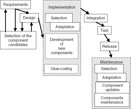
Figure 18.6 shows a simplified and idealized process. Its assumption is that the components selected and used are sufficiently close to the units identified in the design process that the selection and adaptation processes require (significantly) less effort than the components' implementation. Further, the figure shows only the process related to system development and not the supporting processes that have to do with the assessment of components and the development of components.
While development of component-based systems significantly decreases the detailed design and implementation effort during system development, it requires additional effort in other activities. For example, instead of implementing the required functions, developers have to search for components that provide such functionality. Developers must also verify that the selected components provide (or approximate) the desired functionality, and that they can successfully be integrated with other components. A consequence might be that the best components are not selected but rather the components that best fit together.
To make the system development process efficient, many assessment activities can be performed independently, separate from system development. A generic assessment process includes the following activities:
Find From an unlimited component space, find the components that might provide the required functionality.
Select The candidate components found are compared and ranked. A component that is most suitable for the given requirements and constraints is selected. The ranked list of components should be maintained throughout system development so that alternatives for a function can quickly be found.
Verify Verification is part of the component selection process. The first level of verification includes testing functional and certain quality properties of a component in isolation. A second level of verification involves testing the component in combination with other components integrated in an assembly.
Store When a component is assumed to be a good candidate for the current or future applications, it is stored in a component repository. The repository should not only include the component itself, but also additional information (meta-data) that can be useful in further exploitation of the component. Examples of such meta-data are measured results of component performance, known problems, response time, tests passed, and test results.
The component development process is in many respects similar to the system development process: requirements must be captured, analyzed, and defined; the component must be designed, implemented, verified, validated, and delivered. When building a new component, developers will reuse other components and will use similar procedures of component evaluation as for system development. There is, however, a significant difference: components are intended for reuse in (many) different products, many of them yet to be designed. The consequences of this difference are the following:
There is greater difficulty in managing requirements.
Greater efforts are needed to develop reusable units.
Greater efforts are needed to provide component specifications and additional material that help developers and consumers of the components.
Below, we highlight the specific characteristics of activities of a component development and maintenance process.
Requirements Engineering. Requirements specification and analysis is a combination of a top-down and a bottom-up process. The requirements elicitation should be the result of the requirements specification at the system level. However, since the components are also built for future systems, not even yet planned, these system requirements have not necessarily been identified. For this reason the process of capturing and identifying requirements is more complex. It must address ranges of requirements and possible reusability. Reusability is related to generality, thus the generality of the components should be addressed explicitly.
Analysis and Design. The input to the design phase in the component development process comes from system design, system constraints, and system concerns. Since such systems do not necessarily exist yet, the component designer must make many assumptions about the system. Many assumptions and constraints are determined by selecting a component technology. The component technology determines, for example, possible component interactions, certain solutions built into the technology (such as transactions or security mechanisms), and assumptions of system resources (such as scheduling policies). For this reason, it is most likely that a component model and a component technology that implements that model must be chosen at design time.
For a component to be reusable, it must be designed in a more general way than a component tailored for a unique situation. Components intended to be reused require adaptability. This increases the size and complexity of the components. At the same time, they must be concrete and simple enough to serve particular requirements in an efficient way. This requires more design and development effort. Developing a reusable component may require three to four times more resources than developing a component which serves a specific purpose (Mili et al., 2002).
Implementation. Implementation of components is, to a large extent, determined by the component technology selected. The component technology provides support in programming languages and automation of component compositions. It may include many services and provide many solutions that are important for the application domain. Good examples of such support are transactions management, database management, security, and interoperability support for distributed systems provided by component technologies such as .NET, J2EE, or COM+.
Integration. Components are built to be easily integrated into systems. For this reason, integration considerations must be continuously in focus. Usually, component technology provides good support for components integration and integration is being performed on a daily basis.
Test. Test activities are of particular importance for two reasons. First, the component should be very carefully tested since its usage and environment context is not obvious. No specific conditions should be taken for granted, but extensive tests and different techniques of verification should be performed. Second, it is highly desirable that the tests and test results are documented and delivered with the component to system developers.
Release. Release and delivery of the components is the phase where (assemblies of) components are packaged into sets that are suitable for distribution and installation. Such a package not only includes the executable components, but also additional information and assets (meta-data that specifies different properties, additional documentation, test procedures, test results, etc.).
Maintenance. A specific aspect of maintenance in component-based systems is the relation between a component and the systems it is used in. If a bug in a component is fixed, the question is to which systems a new version of the component should be delivered. Who will be responsible for the update: the component producer or each of its consumers? There is also the question of who is responsible for component maintenance: is this a responsibility of the component producer or the producer of the system this component is part of? Do component producers have the obligation to fix bugs and support updates in the systems that make use of their components? Can they provide support in return for additional payment?
Even more difficult problems are related to 'blame analysis'. The issue is related to a manifestation of a fault and the origin of the fault itself. A fault might be detected in one component, but the cause of that fault might be in another component. For example, due to a high frequency of input in component A, component A requires more CPU time. As a consequence, component B does not complete its execution during the interval assumed by component C. Component C then issues a time-out error and a user of component C gets the impression that an answer from component C was not delivered. A first analysis shows that the problem is in component C, then B, then A, and finally in the input to A. The question is: who performs this analysis if the producers of components A, B, and C are different? Such situations can be regulated by contracts between the producers and consumers of the components, but this requires additional effort and, in many cases, it is not possible at all.
The above example shows that maintenance activities can be much more extensive than expected. For this reason, it is important that component producers build a strategy for performing maintenance and take corresponding actions to ensure the realization of this strategy. For example, component producers might decide to provide maintenance support; it is then important that they can reproduce the context in which the error manifested.
Industrial practice has established several approaches to using component-based development. These approaches, while similar in using component technology, have quite different processes and different solutions at the architectural level. In this section, we look at three approaches, all component-based, but with quite different assumptions, goals and, consequently, processes.
This is a top-down approach. Here, components are identified as part of an architectural design. The componentization of the architecture serves as a way of achieving a high level of modularity. Components are not primarily developed for reuse, but rather as pieces to fit into the specified architectures (in the same way as pieces in a jigsaw puzzle). In the implementation, component-technologies (such as .Net) are used, but this is mainly because of the extensive support of component technology for modeling and specification, because of easier implementation, and the possibility of using standard services of a component technology. The genericity of these components is limited: they only have to fit the architecture they were designed for. Reusability and time-to-market issues are of less concern.
An example of this approach would be the software that controls flying an aircraft. It requires a dedicated architecture where each of the components has highly domain-specific functionality. However, a component-based approach would allow replacing of individual components by newer versions.
This approach has a strong top-down direction, but also some bottom-up elements. In contrast to the previous approach, this approach aims to enable efficient development of many variants of products – sometimes called a family of products or a product-line. Such families are common in consumer products such as mobile telephones, televisions, and home audio equipment. Product-line development tries to cater for easily making and maintaining many variants of a products with minimal technical diversity at minimal costs. The solution for this is sought in component-based architectures. This architecture defines the common parts of the system and the parts that are variable.
As an example of this approach, consider a product family of consumer electronics products which includes CD players, DVD players, and mobile phones. In this case, careful design of the architecture would allow an MP3 decoding component to be integrated into the architecture of the CD player, DVD player, and mobile phone.
The component-based character of the architecture plays a crucial role: it enables reuse of components and efficient integration. Composability, reusability, and time-to-market are equally important.
It is characteristic of product lines that the architectural solution has a direct impact on the component model. The component model must comply with the pre-defined reference architecture. In practice, many companies have developed their own component model that suits their proprietary architecture. A second characteristic of product-line architectures is a high degree of concurrency between the component development process and product development process and a combination of top-down and bottom-up procedures.
This is mostly a bottom-up approach: it tries to assemble a system from existing components. The architecture of the system is secondary to the combinations of components that are available.
From the perspective of the system developer, the strongest driver for this approach is time to market: what components exist that we can quickly assemble into a system? For this approach to work, there must be component developers that aim at developing highly reusable functionality. Overall, this approach assumes that the system development process is completely separate from the development processes of components.
While the COTS approach gives instant value in new functionality, there are a number of problems in this approach that complicate its realization: because components were not designed to comply to a component model or to fit together, this approach may run into problems of composability. This may occur if the semantics are not clear or if architectural properties of the components are not properly and adequately documented. For COTS-based development, component assessment plays a much more important role than in the previous two approaches.
As an example of this approach consider a Web store. Web stores now have a fairly crystallized architecture that has a fair amount of commonality with the architecture of many business information systems. A Web-store system can be assembled by buying components that are sold as building blocks on the software market. Typical components include: database, Web server, search engine, payment handler, and stock-control system. In this case, a selection is made of which (combination of) components is most appealing and then an architecture is designed which integrates these components.
Which of these approaches is best or most CBSE-specific? There is no definitive answer. After a surge of enthusiasm in both industry and research, the COTS components market has decreased and does not show revolutionary improvement. One of the reasons for that is that it is difficult to achieve reusability by being very general, effective, and simple and, at the same time, provide attractive functionality. Furthermore, there are problems of trustworthiness (who can guarantee that the component is correct?), component verification, and certification.
The product-line approach has been successful in many domains and its combination with CBSE is a promising approach. Possible threats are the increasing costs of development and maintenance of the component technologies developed internally, and the pace of technological innovations in compilers, debuggers, and integrated development environments. In some cases, the internally developed component technologies are replaced by widely used general-purpose component technologies, while keeping the overall product-line approach.
The vision of assembling systems using independently developed components was first published by McIlroy (1968). In his paper, McIlroy identifies important concepts, such as component, binding, and variability. Following his paper on components, McIlroy worked on the pipes-and-filters mechanism in the Unix operating system. The composition mechanism of pipes and filters is still unique in its genericity and simplicity.
The goals of component-based software engineering are to
reduce development time,
improve productivity, and
improve the evolvability and maintainability of software systems.
In order to enable composition of components the components need to be compatible. This compatibility is achieved by component models that define a set of conventions to which individual components must adhere. Component models are developed to satisfy the quality requirements of particular application domains. In this chapter, we have discussed the common features of component models.
To successfully develop systems in a component-based manner, an architectural plan needs to be in place that organizes how components fit together and how, once assembled, a system meets its quality requirements. An architectural plan is essential when reuse of components is needed across a family of related products, a so-called software product line.
The process of CBSE is characterized by a separation of the development processes of the individual components and the development process of the system that uses components.
(Szyperski, 1998) is a seminal book about component software; it contains chapters on CORBA, COM and JavaBeans. Wang and Qian (2005) discuss many different component models and give extensive code examples. (Heine-man and Councill, 2001) is a comprehensive book on component-based software engineering that covers development processes, design methods, component technologies, and legal issues. Szyperski (2003) discusses the state of the art in component technology. Cheesman and Daniels (2000) discuss the design of component-based systems.
Architecture-driven component development is discussed in (Crnkovic and Larsson, 2002a). Software product lines are discussed in (Clements and Northrop, 2002) and (Weiss et al., 1999). (Morisio et al., 2002b) discuss COTS-based software development. Crnkovic and Larsson (2002b) discuss the challenges of component-based software development and illustrate them with a case study.
Research on CBSE has largely focused on mechanisms for modularization. Only recently, has the notion of composition become recognized as a subject of study in its own right. For example, mixins (Bracha and Cook, 1990) generalize the type of composition provided by the inheritance mechanism of object-oriented languages. (Achermann et al., 2000) discuss language support that enables us to construct more complex composition recipes from simpler ones. Another direction of research is looking to identify the units of software that best match the needs of software engineers when assembling systems. Examples of other types of unit of composition are features (Turner et al., 1999) and aspects (Suvee et al., 2006).
What is a component?
What are the benefits of CBSE?
How are components and component models related?
Discuss the stages of a component life cycle.
How does a component specification differ from a component interface?
Describe four ways in which quality can be managed in a component model.
What is the difference between early binding and late binding?
What is the difference between first-party binding and third-party binding?
How does the component-based software development process differ from the more traditional software development process discussed in Parts I and II of this book?
Why is a component assessment process needed in CBSE?
Why is software architecture important for CBSE?
Discuss the main differences between:
architecture-driven component development,
product-line development, and
COTS-based development.
What are differences between CBSE and reuse?
Recommend which aspects of a component should be covered by its specification.

