
LEARNING OBJECTIVES
To be aware of a number of generic models for structuring the software development process
To appreciate the pros and cons of these models, in particular those of the planning-driven and agile methods
To understand the similarities between software maintenance and software evolution
To recognize that it is profitable to apply software product-line engineering when developing a series of similar systems
To be aware of process modeling as a way to describe software development processes explicitly
Note
To be able to assess progress during software development, one opts for a phased approach with a number of well-defined milestone events. The linear ordering of activities which underlies the traditional software development model, the waterfall model, renders it an impossible idealization of reality. It assumes software development proceeds in an orderly, sequential manner. Real projects proceed in far less rational ways. The waterfall model of software development is not feasible, much as Escher's Waterfall, on the front cover, is infeasible. This chapter discusses various alternative models of the development process.
In Chapter 1, we introduced a simple model of the software life cycle. We distinguished several consecutive phases: requirements engineering, design, implementation, testing, and maintenance. It was stated that, in practice, one often uses more sophisticated process models. In this chapter, we continue this discussion. We introduce various alternative models for structuring the software development process.
Software development projects are often very large projects. A number of people work on such a project for a long time and therefore the whole process needs to be carefully planned and controlled: progress needs to be monitored, people and resources need to be allocated at the right point in time, etc. Earlier on, it was pointed out that progress of a software development project is particularly difficult to measure.
In order to control progress, we use a phased development process in which a number of clearly identifiable milestones are established between the start and finish of the project. We use a similar mechanism when constructing a house: foundations are laid, the first floor is reached, the house is weatherproofed, and so on. Often, installment payments are coupled to reaching those milestones.
Quite often, the milestones identified in a software development project correspond to the points in time at which certain documents become available:
after requirements engineering, there is a requirements specification;
after the design phase, there is a (technical) specification of the system;
after implementation, there is a set of programs;
after testing has been completed, there is a test report.
Traditional models for the phased development of software are, to a large extent, 'document-driven'. The pile of paper that is produced in the course of the project guides the development process. The development process is seen as a series of transformations. It starts with a clear requirements document and ends with running code. In the next section, we discuss the waterfall model, a well-known variation of the process model introduced in Chapter 1. In this variation, a check is performed after each transformation to determine whether we are still on the right track.
These document-driven methods are also known as planning-driven or heavyweight methods. They are planning-driven because of the emphasis on an upfront plan for the whole process and heavyweight because of the emphasis placed on the process.
In many a software development project, change is a fact of life. It may even be the case that the client has only a vague idea of the requirements for the system. In recent years, a number of lightweight, agile methods have been proposed that purportedly deal with these rapidly changing circumstances. These methods advocate not 'wasting' time on expensive planning and design activities early on, but delivering something valuable to the customer as quickly as possible. Based on feedback from the user, the next steps are then taken. Agile methods have evolved from approaches, such as prototyping and Rapid Application Development, that try to dispose of some or all of the drawbacks of the document-driven approach mentioned above. We discuss a number of lightweight approaches to software development in Section 3.2.
Evolutionary models take into account that much of what is called maintenance is really evolution. It would then seem natural to explicitly bear this anticipated evolution in mind from the very start. This is usually not the case. In both heavyweight and lightweight development approaches, the initial development of a software system is in general strictly separated from the subsequent maintenance phase. The major goal of a software development project then boils down to delivering a first version of the system to the user. This may result in excessive maintenance costs later on. In order to be able to properly assess costs and benefits, the total life cycle cost rather than just the development cost should be our primary focus. Going one step further, we may argue that management should concentrate on sets of similar products (known as 'product families') rather than individual products, thereby giving an incentive both to the building of reusable parts and the reuse of (parts of) existing products when developing new ones.
From all the possible life cycle models, we have to choose a particular one for any given project. By and large, heavyweight methods better fit (very) large projects and situations where the requirements can be decided upon at an early stage. Lightweight methods fit situations of rapid change, and projects that do not involve more than, say, 50 people. Different project characteristics, and appropriate ways to control them effectively, are discussed in Chapter 8.
The choice of a particular life cycle model also involves defining the individual steps and phases, their possible interaction, their deliverables, etc. By using an explicit process-modeling language (which may be supported by tools), we increase our understanding of the software process, we are provided with a handle to improve our control of software development, and we are given a baseline for process improvement. This type of process modeling is discussed in Section 3.7. Because of the much larger emphasis on planning, this type of modeling fits better with heavyweight methods.
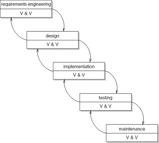
The waterfall model is essentially a slight variation of the model introduced in Chapter 1. The waterfall model is generally attributed to Royce (1970). However, a clearly phased approach to the development of software, including iteration and feedback, can be found in publications from the early 1960s.
The waterfall model particularly expresses the interaction between subsequent phases. Testing software is not an activity which strictly follows the implementation phase. In each phase of the software development process, we have to compare the results obtained against those that are required. In all phases, quality has to be assessed and controlled.
In Figure 3.1, V & V stands for Verification and Validation. Verification asks if the system meets its requirements (are we building the system right) and thus tries to assess the correctness of the transition to the next phase. Validation asks if the system meets the user's requirements (are we building the right system).
Both the model introduced in Chapter 1 and the waterfall model place considerable emphasis on a careful analysis before the system is actually built. We want to prevent putting much energy into constructing a system which later turns out not to satisfy the user's requirements.
We therefore try to identify and tie down the user's requirements as early as possible. These requirements are documented in the requirements specification. On the basis of this document we may verify in subsequent phases whether or not these requirements are being met. Since it is difficult in practice, if not impossible, to completely specify the user's requirements, a regular test should also be carried out with the prospective user. These tests are termed validation. Through the validation steps, we may prevent the system under development diverging from the, possibly incompletely specified, user requirements.
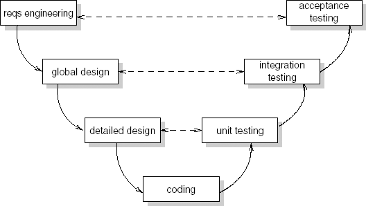
Figure 3.2 depicts essentially the same process model as Figure 3.1. After its shape, it is known as the V-model. The V-model shows how different types of testing are related to the various development phases. For example, during acceptance testing, the complete system is tested against the requirements, under supervision of the user organization. The different test phases are discussed in Section 13.9.
McCracken and Jackson (1981) compare the waterfall model with a shop where the customer is obliged to give an order upon entering. There is no opportunity to look around, compare prices, change one's mind, or decide upon a different menu for today's dinner. Some things can be ordered by mail, but not all. The waterfall model of software development, like Escher's waterfall, is unrealistic.
There is ample quantitative evidence that the classic document-driven model has many shortcomings. In many a software development project, the strict sequencing of phases advocated by the waterfall model is not actually obeyed. Table 3.1 shows the average breakdown of activities across life cycle phases for a number of projects. In this, the label 'coding' refers to a phase which encompasses both implementation and unit testing.
Table 3.1. Breakdown of activities across life cycle phases, after (Zelkowitz, 1988)
Activity | Phase | |||
|---|---|---|---|---|
Design | Coding | Integration testing | Acceptance testing | |
Integration testing | 4.7 | 43.4 | 26.1 | 25.8 |
Coding | 6.9 | 70.3 | 15.9 | 6.9 |
Design | 49.2 | 34.1 | 10.3 | 6.4 |
So, for example, under 50% of the design effort was found to occur during the actual design phase: 34% of the design effort occurs during the coding period and, even worse, over 16% of the design effort takes place after the system is supposed to be finished.
The behavior of individual software designers may be characterized as an opportunistic process (Guindon and Curtis, 1988). Designers move back and forth across levels of abstraction ranging from application domain issues to coding issues. Milestone dates seem to be somewhat arbitrary and a significant part of the activities crosses phase boundaries.
The American Kennel Club says 'The exciting sport of Agility has taken the world by storm. The Agility ring allows handler and dog to run full speed, while having to perform accurately and safely on A-Frames, Dog Walks, See-Saws and a wide variety of jumps and tunnels.' Software engineers are not dogs, but the analogy is clear.
When using a heavyweight development method, it is difficult to change direction. Once the contract has been signed, the development team's job is to deliver the functionality as laid down in the contract. If reality changes, or the user gets a different insight, the change is difficult to realize. It does not fit the architecture, it requires rework not accounted for, it lengthens the agreed schedule, and so on. Once started, software development is like an ocean steamer that does not easily change direction.
This phenomenon has been recognized over the years, and methods such as prototyping and evolutionary development ensued. But these methods still somehow carry an engineering flavor with them. Essentially, they still assume the world is ordered. It may be difficult to pinpoint the true requirements right away, but they will accrue over time.
True agile methods view the world as fundamentally chaotic. They assume change is inevitable. Their focus is to deliver value to the customer as quickly as possible, and not to bother about extensive plans and processes that will not be followed anyway. The essence of agile methods is laid down in the Manifesto for Agile Software Development, published in 2001 by a group of well-known pioneers in this area (Beck et al., 2001). The key values of the agile movement are:
Individuals and interactions are more important than processes and tools.
Working software is more important than comprehensive documentation.
Customer collaboration is more important than contract negotiation.
Responding to change is more important than following a plan.
Agile methods involve the users in every step taken. The development cycles are small and incremental. The series of development cycles is not extensively planned in advance, but the new situation is reviewed at the end of each cycle. This includes some, but not too much, planning for the next cycle.
At the end of each cycle, the system is up and running. That is, there is a working system, one that delivers value to its users. This strongly resembles evolutionary prototyping as discussed in Section 3.2.1. But the difference in wording reflects quite a different attitude. The term prototyping suggests something intermediate, not yet final, temporary. 'Working code' carries a more positive meaning. It denotes something of immediate value, even if not perfect yet.
Agile methods do not have an extensive architectural or design phase up front. After all, it does not make sense to spend much effort on design if you know this will quite likely be a waste of time. It is more effective to only do the design as far as needed for the immediate next step. Agile methods often have a separate activity, known as refactoring, to improve the design after each increment.
Agile methods are people-oriented, rather than process-oriented. They emphasize the human element in software development. Team spirit is considered very important. Team relationships are close. Often, an agile team occupies one big room. The users are on site as well. Agile methods have short communication cycles between developers and users, and among developers.
Finally, agile methods do not spend much energy on documentation. Why spend time on something that will soon be outdated? Rather, agile methods rely on the tacit knowledge of the people involved. If you have a question, ask one of your friends. Do not struggle with a large pile of paper that quite likely will not provide the answer anyway.
Some people contend that agile methods should be 'pure' and exhibit all of the characteristics mentioned above. Others believe that a mixture of planning-driven and agile methods can be productive as well. We concur with the latter view. For instance, in market-driven environments, where there is a strong pressure to deliver functionality in a timely manner, an organization may have a long-term vision of the functionality and a well-thought out architecture, and yet frequently build and deliver functionality. Cusumano and Yoffe (1999) refer to this development style as 'synchronize and stabilize'. Developers frequently synchronize their work, often at the end of each day, by building an executable version of the complete system and testing it. This is called the 'daily build'. Somewhat less frequently, the set of implemented features is stabilized, resulting in a new baseline from which further development takes place. In this style, the 'working software' value from the Agile Manifesto is emphasized most.
In the following subsections, we first discuss prototyping and incremental development, early methods that recognize that a planning-driven approach often does not fit the volatile situation at hand. Rapid application development (RAD) and the dynamic systems development method (DSDM) emphasize customer collaboration and the role of people in the process, and thus exhibit a number of key characteristics of agile methods. Finally, we discuss extreme programming (XP), a 'pure' agile method.
It is often difficult to get and maintain a sufficiently accurate perception of the requirements of the prospective user. This is not surprising. It is, in general, not sufficient to take the existing situation as the one and only starting point for setting up software requirements. An important reason for embarking on a software development project is that one is not pleased with the present situation. What is wanted instead of the present situation is often not easy to determine. This holds even more in cases where we are concerned with a new application and the customer does not know the full possibilities of automation. In such cases, the development of one or more prototypes may help.
Analogies with the development of other products are appealing here. When developing a new car or computer chip, one will also build one or more prototypes. These prototypes are tested intensively before a real production line is set up. For the development of the push-button telephone, about 2 000 prototypes were tested, with variations in form, size and positioning of the buttons, size and weight of the mouthpiece, etc.
It is possible to follow a similar road with software development. In this context, a prototype can be described as a working model of (possibly parts of) a software system, which emphasizes certain aspects. There is, however, one big difference between the development of software and the development of physical products such as cars, chips or telephones: in developing physical products, the highest costs are generally incurred during production, when multiple copies of the product are being produced. In software development, making multiple copies of the product is almost free. If we were to follow the hardware approach to prototyping in software development, and produce a prototype with the same functionality as the final product, we would in fact develop an operational system, with correspondingly high costs. It does not then seem plausible to start all over again and develop the 'real' system in a different way.
Using the definition given above and with the aim of developing a software prototype relatively cheaply, it is important that certain aspects are emphasized. This can be achieved through, for example:
the use of very high-level languages, in which an executable version can be created quickly (this executable, but probably rather inefficient, version can be used to test the usability of the proposed system);
the development of a system with less functionality, in particular as regards quality attributes such as speed and robustness.
One of the main difficulties for users is to express their requirements precisely. It is natural to try to clarify these through prototyping. This can be achieved by developing the user interface quickly. The prospective user may then work with a system that contains the interaction component but not, or to a much lesser extent, the software that actually processes the input. In this way, the user may get a good impression of what the future system will provide him with, before large investments are made to realize the system. Prototyping thus becomes a tool for requirements engineering.
This is illustrated graphically in Figure 3.3, which shows that the various phases are gone through in two ways. The left-hand side of the figure is concerned with the prototyping stages. The iteration corresponds to the user-validation process, whereby new or changed requirements trigger the next cycle. The right-hand side concerns the actual production of the operational system. The difference between the two branches is that, by using different techniques and tools, the left-hand side can be traversed much more quickly and with much lower costs.
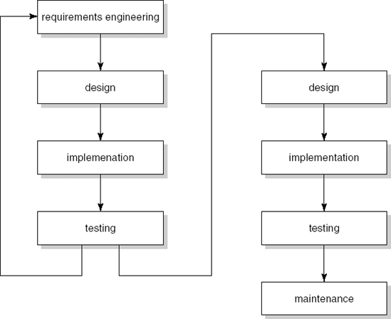
In Figure 3.3, the prototyping phases and the later production phases have been clearly separated. This is appropriate, since we will use different techniques during the actual production phase, put much more emphasis on documentation, and so on. It is even feasible not to carry over the software product from the prototyping phases to the actual production phase, but to explicitly throw it away after the prototyping phases have come to an end. This is known as throwaway prototyping. It is not necessary to do so, though. The prototype may evolve into the final product. The user starts by formulating the raw requirements, on the basis of which a first version of the system is produced. The user starts to work with this system, which leads to new, or changed, requirements. The next version is then developed. After a number of such iterations, the user is satisfied and the last version developed is the product to be delivered. This is known as evolutionary prototyping. In practice, evolutionary prototyping is used much more often than throwaway prototyping. Discarding a (partly) working system is a hurdle that is not easily taken. In agile methods, the phrase 'working code' is often used instead of 'evolutionary prototype'.
Both throwaway and evolutionary prototyping have advantages and disadvantages. Table 3.2 summarizes the pros and cons that have emerged from case studies describing real-world experiences of applying a prototyping approach. Note that some properties can be influenced in both a positive and a negative way. Depending on circumstances, either or both may occur in an actual project. For example, the maintenance cost may go down because user needs are better satisfied or it may go up because development has been done in a quick and dirty way.
Table 3.2. Some observed pros and cons of prototyping
Advantages |
–The resulting system is easier to use |
–The resulting system has fewer features |
–User needs are better accommodated |
–The design is of higher quality |
–Problems are detected earlier |
–The resulting system is easier to maintain |
–The development incurs less effort |
Disadvantages |
–The resulting system has more features |
–The design is of lower quality |
–The performance of the resulting system is worse |
–The resulting system is harder to maintain |
–Team members should be more experienced |
Users and developers are generally more positive about systems developed using a prototyping approach than about systems developed in a waterfall process. This positive attitude concerns both the development process and the resulting product. Users feel more involved in the development process and have fewer conflicts with the designers. The extensive user involvement results in systems which better satisfy user needs.
Since users need not express all their requirements up front in a prototyping approach, there is less tendency to ask for bells and whistles (unnecessary extra features). As a consequence, the end result is a leaner system of which the functionality closer matches the real user requirements. If users are shown a working system at an early stage and are given the opportunity to try it out, chances are that problems are detected at an early stage as well. This prevents a waste of manpower which would otherwise be needed to redo part of the work. If users are in a position to influence and modify the design, the system features will better reflect their requirements and the system will be easier to use.
The use of special-purpose prototyping tools or languages makes it easy to add features. Since the time interval between successive versions of the prototype is small, users may think that it is easy to realize new features and may specify additional requirements. These aspects of prototyping may result in systems having more, rather than fewer, features.
Prototyping involves iterative design steps and, because of the repeated attention to the design, its quality may increase. Since it is known in advance that the design will evolve during subsequent prototyping steps, greater attention will be given to quality factors such as flexibility and modularity and, as a result, design quality may improve as well. In throwaway prototyping, the quality of the final design is often higher because of the learning experience of the prototyping steps. Also, this final design step is hardly, if at all, patched up because of rework actions. Because of these aspects, the resulting systems are often found to be easier to maintain.
On the other hand, prototyping generally does not enforce strict design and development standards. If we are concerned with a short development time, certain necessary activities will receive less attention. The chances are that documentation is sacrificed for speed. Because of additions resulting from frequent rework steps, the design quality of an evolutionary prototype may deteriorate. For that reason too, the resulting system may be less maintainable. Especially in evolutionary prototypes, the robustness of the system will often be less than is customary with a more traditional approach. In agile methods, refactoring is applied to counteract this phenomenon. Finally, performance tends to be worse because attention is focused on functionality and performance measures are either not taken at all or are taken at a point in time at which they have become too difficult to realize.
It is generally felt that prototyping projects require an experienced team. Prototyping involves making far-reaching design decisions, especially during early iterations. In each iteration, user requests have to be weighed against each other and against the ease and cost of their realization. Inexperienced team members are more likely to make poor choices, thereby seriously threatening the success of a prototyping effort.
From this discussion, we may gather the following recommendations for the use of prototyping techniques:
prototyping is particularly useful in situations where the user requirements are unclear or ambiguous, when it can be a good way to clarify those requirements;
prototyping is also particularly useful for systems with a considerable emphasis on the user interface and which need a high degree of user interaction;
users and designers must be well aware of the prototyping approach and its pitfalls: users should realize that changing software is not all that easy and that a prototype is not a production-quality system; designers should be aware of the characteristics of prototyping projects and not become frustrated by frequent changes in user requirements;
prototyping must be planned and controlled: limits must be imposed on the number of iterations; there must be explicit procedures for documenting and testing prototypes; the positive aspects of the traditional approach, which make the process manageable and controllable, should be applied to prototyping.
By taking appropriate counter-measures, the potential disadvantages of prototyping can be guarded against. Prototyping is, then, a viable alternative process model for many a software development project.
In the preceding section, we discussed a way of using prototypes in which the final system is the last of a series of prototypes. Under careful management control, in order to ensure convergence, the next version is planned to accommodate new or changed user requirements. There is another way to work towards the final system in a number of iterations: we proceed incrementally. The functionality of the system is produced and delivered to the customer in small increments. Starting from the existing situation, we proceed towards the desired situation in a number of (small) steps. In each of these steps, the phased approach that we know from the waterfall model is employed.
Developing software in this way avoids the 'Big Bang' effect (in which nothing happens for a long time and then, suddenly, there is a completely new situation). Instead of building software, the software grows. With this incremental approach, the user is closely involved in planning the next step. Redirecting the project becomes easier since we may incorporate changed circumstances more quickly.
Incremental development can also be used to fight the 'overfunctionality' syndrome. Since users find it difficult to formulate their real needs, they tend to demand too much. Lacking the necessary knowledge of the malleability of software and its development process, they may be inclined to think that everything can be achieved. As a consequence, essential features appear next to bells and whistles in the list of requirements. Analysts are not able to distinguish one from the other, nor are they able to accurately estimate the effort required to implement individual features. Chances are, then, that much effort is spent on realizing features that are not really needed. As a result, many of today's systems offer rich functionality yet are, at the same time, ill-suited for the task at hand. For one thing, these systems are difficult to use simply because of the complexity incurred by their rich functionality.
With the incremental approach, attention is first focused on the essential features. Additional functionality is only included if and when it is needed. Systems thus developed tend to be leaner and yet provide sufficient support to their users. With the incremental approach, the most difficult parts or the parts that have the highest risk with respect to successful completion of the project are often tackled first.
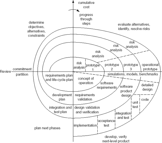
Following this line of thought, Boehm (1988) suggests a spiral model of the software development process, in which each revolution of the spiral gives rise to the following activities:
identify the subproblem which has the highest associated risk;
find a solution for that problem.
The various process models already discussed can be coupled with Boehm's spiral model in a natural way (see Figure 3.4):
If obtaining the proper set of user requirements is seen as the area with highest risk, follow the spiral a few times around to solve this subproblem (i.e., prototype).
If the main issue is to obtain a robust and well-documented system from a precise requirements specification, follow the spiral once, using the traditional process model with its phases and corresponding milestones as intermediate steps.
If developing software incrementally, track the spiral a number of times, once for each increment.
During maintenance, the reported errors or changing requirements are triggers to track the spiral.
Viewed this way, the spiral model subsumes the other process models discussed so far.
Incremental development is strongly advocated by Gilb (1988). It is doubtful whether the time increment advocated by Gilb, up to a maximum of a few weeks, is always reasonable. But the advantages of incremental development are considerable, even with different time increments. Surprises that lurk within the traditional approach and that pose considerable difficulties on the management side of software development projects can be greatly diminished when software is developed and delivered incrementally.
Rapid Application Development (RAD) has a lot in common with other iterative development process models. It emphasizes user involvement, prototyping, reuse, the use of automated tools, and small development teams. In addition to that, it employs the notion of a time box, a fixed time frame within which activities are done. In most development models, a set of requirements is fixed and then the project attempts to fulfill these requirements within some estimated period of time. Within RAD, the time frame is decided upon first and then the project tries to realize the requested functionality within that time frame. If it turns out that not all of the functionality can be realized within the time frame, some of the functionality is sacrificed. The agreed deadline however is immovable.
The RAD life cycle consists of four phases:
requirements planning,
application design,
construction,
cutover.
The requirements planning and application design phases have much in common and may be combined for smaller projects. Together, they typically take less than two months. The main techniques used in these phases are known as joint requirements planning (JRP) and joint application design (JAD). Both these techniques make heavy use of workshops in which the developers and the prospective users work together (hence the adjective joint).
The goal of the JRP workshop is to get the requirements right the first time. For that reason, it is imperative that the key players, i.e. the end users of the system, are present. Requirements are prioritized, since it is likely that not all of them will be implemented in the first version of the system. This requirements prioritization is known as triage. Triage usually means a process used on the battlefield and in emergency rooms to sort injured people into groups based on their need for or likely benefit from immediate medical treatment. In RAD, the triage process is used to make sure that the most important requirements are addressed first. The result of this process is often a prioritization denoted by the acronym MoSCoW:
Must haves are requirements that are definitely needed.
Should haves are requirements that are important, but not absolutely needed for a usable system.
Could haves are requirements that are only implemented if time allows.
Won't haves are requirements that will be left for the next iteration.
As an example, consider the development of a Library Information System. The Must have category would include the ability to borrow and return an item and to enroll as a member. The Should have category might include facilities to reserve an item. The Could have category might include the ability to handle fines for items returned late. Finally, the Won't have category in the first iteration might include functions to profile users and notify them of newly arrived items.
It is customary to have two JAD workshops during the design phase. Again, the end users play an essential role in these workshops. The first JAD workshop yields an initial design of the system. The developers then construct a prototype, to be experimented with by the users. This prototype is evaluated during the second JAD workshop, improvements are decided upon, and the design is finalized.
The system is constructed by a highly skilled team of about four people, a 'Skilled With Advanced Tools' (SWAT) team (see also Section 5.2). The SWAT team becomes involved after the first JAD workshop. The team typically does its job in less than two months. In order to be able to do so, heavy use is made of tools, and existing components are reused whenever feasible. Within the time allotted (the time box), the SWAT team constructs a series of evolutionary prototypes. Developers and users work closely together during this process. Each prototype is reviewed by the users and the review sessions result in requests for enhanced or changed functionality. The agreed upon time frame is not exceeded. If necessary, some of the functionality is sacrificed instead.
For a SWAT team to operate successfully and deliver a good result in a very short time span, it has to feel a definite 'ownership' of the problem to be addressed. In such a situation, it is not very helpful if time estimates and deadlines are fixed by some manager. Instead, the SWAT team itself estimates the time, the SWAT team decides upon the number and length of the time boxes, and the SWAT team decides which functionality to implement in each iteration.
During the cutover phase, the final testing of the system takes place, users are trained, and the system is installed.
There are many variations on the RAD process model described above. For example, it is possible to have explicit time boxes for the construction of each of the intermediate prototypes. It is also possible to have JRP or JAD sessions after each prototyping cycle. The main ingredients, however, remain: prototyping, considerable user involvement, SWAT teams, and time boxes.
JRP and JAD have much in common with a design method known as participatory design (PD) or the Scandinavian school of software development. They both emphasize end-user involvement but they differ, however, in their goals. User involvement in JRP and JAD is primarily intended to speed up the process of producing the right system. User involvement in PD is motivated by a strong interest in the social context of the work environment.
The dynamic systems development method (DSDM) is a well-known framework that builds on RAD. DSDM is based on the nine principles depicted in Table 3.3. DSDM is a non-profit framework maintained by the DSDM Consortium (see www.dsdm.org). A high-level description of the framework is given in (Stapleton, 2003). The complete set of DSDM practices is only available to members of the DSDM Consortium.
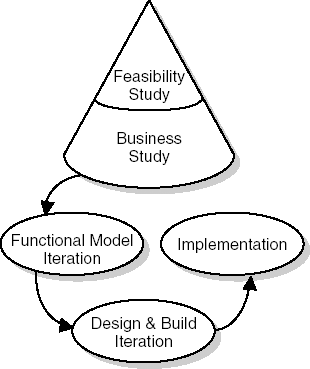
The DSDM process has five phases (see Figure 3.5):
In the feasibility study, the suitability of DSDM for the current project is assessed. This is different from a more traditional feasibility study, where the emphasis is on whether a solution is feasible at all. Next to questions such as 'Can we build this system at all?', the question 'Is DSDM appropriate for this project?' has to be answered as well. Characteristics that make DSDM a feasible approach reflect the principles of the method: it must be possible to identify the users of the system, the system should not be too large, and not all requirements should be known up front.
Table 3.3. The principles of DSDM
Principle
Description
Active user involvement is imperative.
Users support the team throughout the project, not just during requirements elicitation and acceptance testing. The communication channel between the development team and the users is kept short.
The team must be empowered to make decisions.
The team must be able to make quick decisions. Momentum is lost if the team has to wait for external approval of every small decision.
The focus is on frequent delivery of products.
Frequent delivery allows for frequent feedback from the user community and control of the decision-making process by managers.
Fitness for business purpose is the essential criterion for acceptance of deliverables.
The emphasis is on delivering the right product, not on gold-plating or conformance to specifications.
Iterative and incremental development is necessary to converge on an accurate business solution.
Requirements cannot be completely determined up front. Systems need to evolve and rework is a fact of life.
Changes during development are reversible.
A wrong path may be taken and backtracking is required to get to a safe point again.
Requirements are baselined at a high level.
The high-level requirements are determined during the business study phase and detailed requirements are determined during later iterative phases.
Testing is integrated throughout the life cycle.
Testing is not postponed until after coding has finished. It is done incrementally, after each component is written.
A collaborative and co-operative approach between stakeholders is essential.
Responsibilities are shared and developers need support from end-users to decide what to develop.
The business study results in a high-level description of the business processes relevant to the system. These are determined using facilitated workshops (such as JRP) and result in a high-level baseline. In this phase, the high-level architecture is determined as well.
The functional model iteration results in analysis models, prototypes, and implementation of the major functional components. Iteration is done in time boxes of typically two to six weeks. Each iteration consists of four activities: identify what you will do; agree on how you will do it; do it; and check that you have done it.
During the design and build iteration, the system is engineered to a sufficiently high standard. Here too, work is done in time boxes of typically two to six weeks, and the same four activities as in the functional model iteration are performed. Though the emphasis of functional model iterations is on deciding what to build, and that of design and build iterations is on building a properly engineered solution, the distinction between those two types of iteration is not always clearcut.
In the implementation phase, the system is carried over to the customer environment. This phase also includes user training.
Extreme programming (XP for short) is a pure agile method. XP is based on a number of best practices that have been known for a long time. XP takes these practices to extreme levels.
For instance, we know that code reading by your colleagues, such as is done in walkthroughs and code inspections (see also Chapter 13) is a very effective test method. In XP, one does this all the time: two programmers work together at one computer screen. One of them does the coding, the other one looks over his shoulder, gives advice, notices small slips, asks questions, and so on. They act as pilot and co-pilot. At any point in time, the roles may shift. This practice is called pair programming.
The full set of XP practices is given in Table 3.4. Typically, an XP team is not too big and occupies one room. Planning meetings are very short and involve the immediate functionality to be delivered to the customer. Planning includes both the customer and the technical people. The customer has to set priorities, determine dates of releases, and so on. The customer describes desirable features of the system in stories and records them on index cards. The technical people estimate how long it will take to implement a story and decide on the order in which stories within one release will be implemented.
Table 3.4. Practices in extreme programming
XP practice | Description |
|---|---|
The planning game | The scope of the next release is quickly determined. When necessary, the plan is updated. |
Small releases | A simple system is first realized, then other versions are released in short cycles. |
Metaphor | A simple metaphor is used for the whole system. |
Simple design | The design is kept as simple as possible at any point in time. Complexity is removed as soon as possible. |
Testing | Programmers continuously write unit tests and customers write acceptance tests. |
Refactoring | The system is restructured without changing its behaviour, to improve quality. |
Pair programming | All code is written by two programmers at one machine. |
Collective ownership | Anyone can change any code, anywhere, at any time. |
Continuous integration | The system is integrated and built many times a day. |
40-hour week | As a rule, the team works only 40 hours per week. Working overtime should be the exception. |
On-site customer | A real user should be on the team, full-time. |
Coding standards | Coding standards are established, to ease communication. |
In XP, the design is kept as simple as possible. Since the future is, after all, unclear, there is no use designing a grand scheme that will not be followed anyhow. So the design only covers the current version of the system. After a task is accomplished, the system is checked to see how it can be improved (by removing duplicate code, making it simpler, making it more flexible). This is called refactoring. Refactoring need not be restricted to one's own code. Everyone is responsible for the whole system. To make this work, the team needs to set coding standards.
When a team works on implementing a story, at the same time it writes tests to check the implementation of that story. Before the new code is checked in, all these tests have to run successfully. After the code has been checked in, the full test suite is run and again all tests have to run successfully. If they do not, the new code is removed to fix it. This way, there always is a running system.
XP is based on five principles that drive its practices:
Rapid feedback Feedback is obtained quickly, within hours, or at most a few days. As each small piece added is tested, developers immediately learn what works and what doesn't. As a running system is delivered frequently to the customer, the customer learns what value the system offers and what features are needed next.
Simplicity Today's job is done today and tomorrow's job is left for tomorrow. Do not build in extra complexity so that a certain class becomes more flexible and may be reused if a certain feature is added. If and when this feature is needed, it will be added and code will be refactored to make it simpler.
Incremental change In XP, things change in small increments. The plan changes a little at a time, the design changes a little at a time, the team changes a little at a time, etc.
Embracing change By not planning, designing or coding more than is needed right now, most options for the future are kept. Only the most pressing problem is tackled today. The rest is left for tomorrow.
Quality work Quality is a must. The team should find pride in delivering excellent quality.
As noted before in this chapter, agile methods are suited for certain projects, but not for all. This is certainly also true for XP, the most extreme agile approach. If requirements are unsure, the system is not too big, and the customer can be on site, XP deserves serious consideration. Early sources recommend using all of XP's practices, since they reinforce each other. But nowadays there also exist many approaches that adopt one or a few of XP's practices.
The Rational Unified Process is an iterative development process, geared towards the development of object-oriented systems. It comes with a lot of tool support; there are sources and templates that a company can load onto an intranet; and there are sources and templates for various kinds of documents on the Internet. It complements the Unified Modeling Language (UML). RUP might be viewed as being between document-driven and agile methods. It has a well-defined process and includes reasonably extensive upfront requirements-engineering activities, yet it emphasizes stakeholder involvement through its use-case-driven nature. Its two-dimensional process structure is depicted in Figure 3.6.
RUP distinguishes four phases: inception, elaboration, construction, and transition. Within each phase, several iterations may occur. Along a second dimension, RUP distinguishes nine 'workflows', such as a requirements workflow and a test workflow. These workflows group logical activities and might extend over all phases, with varying levels of attention. For instance, the requirements workflow is likely to get a lot of attention during the early phases, while the deployment workflow is most relevant in the transition phase. This is illustrated by the undulating shapes next to each workflow in Figure 3.6, which allows us to differentiate between successive iterations and stress that different iterations have a different emphasis. It recognizes that requirements engineering, design, and other workflows are ongoing activities rather than phases with a strict start and end time.
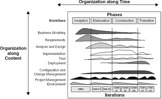
Figure 3.6. Process structure of RUP (Source: P. Kruchten, The Rational Unified Process: An Introduction, p. 23, © 2000 Pearson Education, Inc. Reproduced by permission of Pearson Education. All rights reserved.)
The inception phase focuses on getting the objectives clear: what is the scope of this project, what are its boundaries, and what are the acceptance criteria that will be used when the system is delivered to its customers? During this phase too, the overall cost, schedule, and risks are estimated. Critical use cases are developed, as well as a candidate architecture. At the end of this phase, the business case for the system must be clear. This might be the input to a go/no-go decision (a decision whether or not to go ahead with the development).
The elaboration phase is mainly targeted at analyzing the problem domain and obtaining a sound architecture. At the end of this phase, most use cases will be identified and all major risks must be resolved.
The construction phase is a manufacturing, building process. The emphasis is on developing deployable products. Complete components are developed and thoroughly tested. User manuals are written. At the end of this phase, the first operational version of the system, the beta release, is ready.
In the transition phase, the system is released to the user community and beta-tested. During this phase, databases may have to be converted, users are trained and, in case of a replacement system, the legacy system being replaced is phased out.
RUP is based on a series of best practices (see Table 3.5) that have evolved over the years. Many of these best practices, of course, are also present in other development models. A strong point of RUP is that it provides a balanced integration of the best practices. Given its background, it is no surprise that RUP is geared towards the development of object-oriented systems. But RUP is suited for projects with widely different characteristics. The tuning of RUP to the situation at hand, however, is left to the user of the method.
Table 3.5. Practices of RUP
Practice | Description |
|---|---|
Iterative development | Systems are developed in an iterative way. This is not an uncontrolled process. Iterations are planned and progress is measured carefully. |
Requirements management | RUP has a systematic approach to eliciting, capturing and managing requirements, including possible changes to these requirements. |
Architecture and use of components | The early phases of RUP result in an architecture. This architecture is used in the remainder of the project. It is described in different views. RUP supports the development of component-based systems, in which each component is a nontrivial piece of software with well-defined boundaries. |
Modeling and UML | Much of RUP is about developing models, such as a use-case model, a test model, etc. These models are described in UML. |
Quality of process and product | Quality is not an add-on, but the responsibility of everyone involved. The testing workflow is aimed at verifying that the expected level of quality is met. |
Configuration and change management | Iterative development projects deliver a vast amount of products, many of which are frequently modified. This asks for sound procedures to do so, and appropriate tool support. |
Use-case-driven development | Use cases describe the behaviour of the system. They play a major role in various workflows, especially the requirements, design, test and management workflow. |
Process configuration | One size does not fit all. Though RUP can be used 'as-is', it can also be modified and tailored to better fit specific circumstances. |
Tool support | To be effective, a software development methodology needs tool support. RUP is supported by a wide variety of tools, especially in the area of visual modeling and configuration management. |
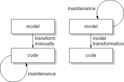
In traditional software development approaches, we build all kinds of models during requirements engineering and design. These models may be expressed more or less formally. Usually, the models are not all that formal. Typical examples include a list of requirements in natural language, a box-and-line diagram illustrating a global design, and UML diagrams; see also Chapter 10. The ultimate model is the source code, which is as formal as it can get.
The transitions between the various models are done manually. That is, we manually translate a requirements model into a design model. The design model is next manually translated into code. Any evolution is accomplished by changing the last model in the chain, i.e. the source code. Since we are usually pressed for time, the earlier requirements and design models are often not updated, so that they quickly become outdated.
In model-driven architecture (MDA)[4], the attention shifts from writing code to developing models. The design model is captured in a very precise formalism and is automatically translated into source code. Subsequent evolution then takes place at the modeling level. Once changes have been made there, the next version of the system is generated automatically. So maintenance is not done at the source code level, but at the model level. This paradigm shift is depicted in Figure 3.7.
In MDA, several models are distinguished. The main ones are the computation-independent model (CIM), the platform-independent model (PIM) and the platform-specific model (PSM). The CIM is the most abstract model; it captures the requirements. The CIM is transformed into the PIM, which describes the functionality of a system, without any platform-specific details. The PSM includes details of the target platforms, such as .NET or J2EE. Finally, the PSM is transformed into executable code.
The transformations from PIM to PSM, and from PSM to code, are automated. The transformation from CIM to PIM is not automated. Many discussions of MDA concentrate on the fully automated parts and leave out the CIM altogether. The model transformations from PIM to PSM and from PSM to code are defined in a specific language that defines how concepts from one level map onto concepts from another level. For each combination of PIM and PSM, such a model transformation must be defined. And likewise for each combination of PSM to code. However, once such a mapping is defined, it can be reused over and over again.
MDA is an initiative of the Object Management Group (OMG), a not-for-profit organization also responsible for UML (see Chapter 10). MDA's vision of developing software at the level of abstract models, and automating the actual generation of code, is not new. Earlier attempts include executable specifications, fourth-generation languages, and so on. These earlier attempts have largely failed. Some critics claim that MDA won't work either. But the argument is still open.
Old payroll programs never die;
they just get fat around the middle.
Robert Granholm (Datamation, 1971)
In Chapter 1, it was pointed out that a considerable maintenance effort is inevitable. Each maintenance task, whether it concerns repairing an error or adapting a system to new user requirements, in principle entails all aspects of the initial development cycle. During maintenance, we also have to analyze the problem and conceive a design which is subsequently implemented and tested.
The first big difference is that these changes are being made to an existing product. However, during initial development we often do not start from scratch either. If an existing organization decides to automate its order administration, the system may have to interface with already existing systems for, say, stock administration and bookkeeping. Thus, maintenance activities differ in degrees from initial development, rather than fundamentally. This relative difference is even more apparent when the system is prototyped or developed incrementally.
The second main difference, time pressure, has a much larger impact. Time pressure is most strongly felt when repairing errors, for then it is quite possible that certain parts of the organization have to shut down because the software is not operational. In such cases, we have to work against time to identify and repair the errors; we often skip a thorough analysis and design step and simply patch the code. The structure of the system tends to suffer from such patches. The system's entropy increases, which hampers later maintenance activities. Worse still, the system's documentation may not be updated. Software and the corresponding documentation then grow apart, which also hampers future maintenance activities. A more elaborate discussion of maintenance issues is given in Chapter 14.
Lehman and his co-workers have extensively studied the dynamics of software systems that need to be maintained and grow in size. Based on those quantitative studies, they formulated the following laws of software evolution:
Continuing change A system that is being used undergoes continuous change, until it is judged more cost-effective to restructure the system or replace it by a completely new version.
Increasing complexity A program that is changed becomes less and less structured (the entropy increases) and thus becomes more complex. One has to invest extra effort in order to avoid increasing complexity.
Self-regulation Software evolution processes are self-regulating and promote smooth growth of the software.
Conservation of organizational stability (invariant work rate) The overall progress in software development projects is statistically invariant.
Conservation of familiarity A system develops a constant growth increment to sustain the organization's familiarity with the system. When this increment is exceeded, problems concerning quality and usage will result.
Continuing growth The functionality of a system needs to continuously increase in order to maintain user satisfaction.
Declining quality The quality of a system declines unless it is actively maintained and adapted to its changing environment.
Feedback system Software evolution must be seen as a feedback system in order to achieve improvements.
In an early publication, Lehman (1974) compares the growth of software systems with that of cities and bureaucracies. He makes a distinction between progressive and anti-regressive activities in software development. Lehman considers this model also applicable to socio-economic systems. In a city, for instance, progressive activities contribute to an increase in the living standard or quality of life. Anti-regressive activities, such as garbage collection, serve to maintain the status quo. If insufficient attention is paid to those anti-regressive activities, decline will set in. Anti-regressive activities often are not interesting, politically speaking. It is an investment in the future, which had better be left to others. (The same phenomenon can be observed in the growth of the chemical industry and the resulting pollution problems.)
According to Lehman, the same kinds of activity occur within a software development project. Generating new code and changing existing code are progressive activities. These are interesting, challenging and rewarding activities. They provide the user with new or better functionality. Writing documentation, improving the structure of the code, and maintaining good communication between the people involved are anti-regressive activities. Neglecting these activities may not be harmful in the short term, but certainly will be in the long term. For each system, we have to look for a proper balance between these kinds of activity.
The law of self-regulation is illustrated by Figure 3.8 which depicts the growth pattern of system attributes over time. System attributes include the length (measured in lines of code), the number of modules, the number of user-callable functions, etc. The time axis may denote the release number, the number of months the system is operational, or a similar measure. (The actual data studied by Lehman concerned the relation between the number of modules and the release number of the OS360 operating system.)
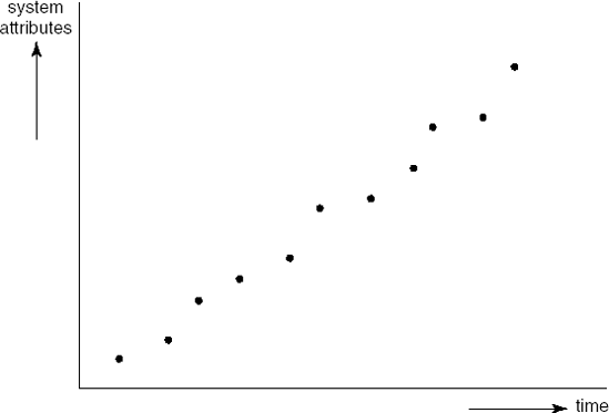
The relation depicted in Figure 3.8 is almost linear. The ripples in the figure are very regular as well. Periods of more than linear growth alternate with periods of less than linear growth. Lehman explains the periods of more than linear growth by pointing to the pressure from users to get more functionality as fast as possible. The developers or maintainers tend to bend under this pressure. As a consequence, they use tricks and shortcuts in the code, documentation lags behind, errors are introduced and the system is insufficiently tested. After a while, more attention is paid to anti-regressive activities: code needs to be refactored and documentation brought up to date before further growth is possible. The two kinds of activity stabilize over time.
The law of conservation of organizational stability seems rather surprising at first sight. Lehman and Belady (1985) found that such things as manpower and other resources do not correlate at all to the speed with which systems grow or change. Apparently, large systems are in some sort of saturated state. More people can be kept at work but, in the long run, they have no perceived impact on the evolution of the system.
More than average growth in some version of a system was, in Lehman and Belady's observations, almost always followed by a less than average growth in the next version (as expressed in the law of conservation of familiarity). In one of the systems they investigated, a substantially higher growth inevitably led to problems: lower reliability, higher costs, etc. Apparently, an organization has to sustain sufficient familiarity with its software. Here too, self-regulating feedback was observed.
From the preceding discussion, it follows that we have to be alert during maintenance. We have to preserve quality at each and every step. We may try to preclude the dangers sketched above by explicitly engaging ourselves in the various development phases during maintenance. The cyclic process followed during initial development then occurs during maintenance too. As with prototyping, the time needed to go through the complete cycle will, in general, be much shorter than during initial development. This way of looking at maintenance closely resembles the evolutionary view of software development. Realization of the first version of a software system is only the first step. True enough, this first step is more costly than most of the steps that follow, but it is not fundamentally different. In Chapter 1, we already noticed that putting maintenance on a par with development may also have positive effects on the social and organizational environment in which software development takes place.
The waterfall model gives us a static view of the system to be developed. Reality is different. In developing software, and in particular during maintenance, we are concerned with an evolving system. As we remarked before: software is not built, it grows.
When similar products are developed, we may hope to reuse elements from earlier products during the development of new products. Such is not the habit in software development though. In many an organization there is no incentive to reuse elements (code, design, or any other artifact) from another system since that is not what we are being paid for. Similarly, there is no incentive to produce reusable elements, since the present project is all that counts.
As an alternative, we may conceive of the notion of a software product line, a set of software systems that share elements. In a software product line, reuse is planned, not accidental. To keep the scope within reasonable boundaries, the planned reuse is tied to a given domain.
Suppose we have developed a successful library system for our computer science faculty library. Chances are that we will be asked to develop a similar system for, say, the faculty of earth sciences. We reuse as much as possible from our first system but it is likely that some finetuning is needed to satisfy the other faculty. They may have maps that may be borrowed and that require some specific handling. Another faculty may come and ask for a third system. And so on. Rather than being reactive and reusing suitable elements from previous efforts, we may also be proactive and plan for the development of a series of systems in the domain of library automation right from the beginning. This involves two processes: domain engineering and application engineering.
In domain engineering, we analyze the domain for which we are going to develop. This process has a life cycle of its own. It results in a set of reusable components that form the basis for the products to be developed. Usually, a reference architecture for all products to be developed is produced as well. An important step in this process is to decide on the scope of the product line. Are we going to develop a product line for just university libraries, or for libraries in general? The former is simpler but has a more limited market. The latter potentially has a bigger market, but is likely to result in a more complex overall architecture and more complex products. Scoping for product lines is a difficult issue. It is influenced by the strategy of the organization and requires insight into the likely evolution of the domain. Finally, the domain engineering process yields a production plan, a guide to how to develop products within the product family.
Application engineering concerns the development of individual products. It usually follows a waterfall-like scheme. Its inputs are the outputs of the domain engineering process: the reference architecture, the production plan, and the set of reusable assets.
Product-line organizations often separate domain-engineering activities from application-engineering activities. Effectively, these activities then constitute separate projects. The development of an individual product may result in new or adapted components that lead to adaptations at the product-family level, which in turn affects the development of subsequent products. Consequently, there are feedback loops from the application-engineering process to the domain-engineering process and vice versa.
Software product lines are particularly suitable in domains where there is a lot of variation in quite similar products, such as mobile phones, television sets, or cameras. Companies operating in these domains have pioneered the product-line field. A more elaborate discussion of software product lines and other component-based approaches that involve separate development processes for components and applications is given in Chapter 18.
Without a repeatable process, the only repeatable results you are likely to produce are errors.
(Macala et al., 1996)
In the 1980s, Osterweil launched the idea of describing software development processes as programs. These process programs are written in a process programming language. Like other programming languages, process programming languages have a rigorously defined syntax and semantics. As a simple example, consider the Pascal-like description of a review process in Figure 3.9.[5] It describes the consecutive steps of a review process. The process has two inputs: the document to be reviewed and some number which serves as a threshold. The routine returns a Boolean indicating whether or not another review is to be scheduled.
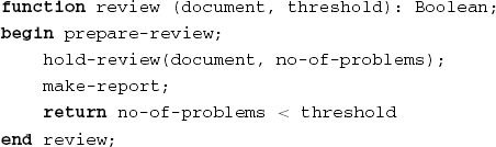
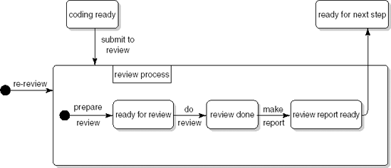
In Figure 3.9, the review process is described in terms of the successive activities to be performed: first, the review is prepared, then the meeting is held, and finally a report is made. We may also describe the process in terms of the states it can be in. After the preparation activities (distribution of the document amongst participants, scheduling of a meeting, and so on), the document is ready to be reviewed. After the meeting has been held, a report can be written. After the report has been written, further steps can be taken. Figure 3.10 uses UML notation for state machine diagrams (see Section 10.3.2) to describe the review process in terms of states and transitions between states. The box labeled review process describes the review process proper. The inputs and outputs to the process are indicated by arrows leading into and out of the box.
Petri nets provide yet another formalism to describe process models. Figure 3.11 gives a Petri net view of the review process. A Petri net is a directed graph with two types of node: places and transitions. A place is depicted as a circle. It denotes a (partial) state of the system. A place is either marked or unmarked. In Figure 3.11, the place code ready is marked but review scheduled is not. A transition is depicted by a straight line. A transition receives input from one or more places, and delivers output to one or more places. The inputs and outputs are denoted by arrows leading to and from a transition. A transition denotes an activity which can be performed (in Petri net terminology, 'fired') if all of its input places are marked. Places can thus be thought of as preconditions for activities. In Figure 3.11, the review meeting cannot be held, since it has not been scheduled yet. Once it has been scheduled, the corresponding place is marked and the transition can be fired. The markings are then removed from all of the input places and all of the output places are marked instead.
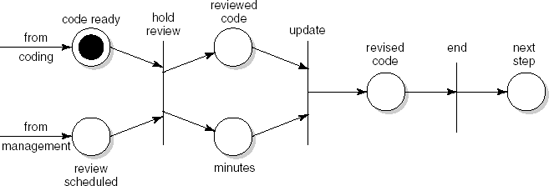
Petri nets are an attractive modeling technique for processes, since they allow a certain amount of nondeterminism and parallellism. For example, the process in Figure 3.11 does not specify the order in which coding and scheduling activities are to be performed. They may go on in parallel; synchronization takes place when both are finished.
A precise description of the software process, be it in a programming-language notation, a graphical notation, or otherwise, serves three main purposes:
It facilitates understanding and communication. In a software development project, people have to work together. They thus need to have a shared view of the processes to be carried out and the roles they are to play in those processes. Either model of the review process given above can be used for this purpose.
It supports process management and improvement. A precise description of activities to be performed can be used by project management to assign tasks and to keep track of who is doing what. If the software development process is to be improved, you first have to know what the current process is, i.e. it has to be modeled.
It may serve as a basis for automated support. This automated support may guide or enforce the order in which tasks are carried out. For instance, a reviewer may automatically be sent a message indicating that a certain piece of code is ready for review as soon as its author releases that code. The automated support may also be used to monitor and track progress, collect process information and metrics, and so on.
The description of the review process in Figure 3.9 is very deterministic. It can be completely automated and executed without human intervention. In general, the work that is being modeled will be carried out by both humans and machines. The neutral term enactment is used to denote the execution of a process by either humans or machines. Support for process enactment is often combined with support for configuration management (see Section 4.1).
Though the precise modeling of the software process has definite advantages, the resulting process formality, or even rigidity, holds certain dangers and limitations as well:
Many aspects of the software development process are heuristic or creative in nature and do not lend themselves to an algorithmic description. For example, the actual debugging or design processes will be quite difficult to capture in a process model.
A process model is a model and, thus, a simplification of reality. For example, the above models of the review process do not specify what to do if the minutes of the meeting are not delivered or the review is not held because the author of the code is on sick leave, and so on.
Process models often focus on the transformation of artifacts, such as code, a requirements specification, or a test plan. The progression of stages through which the artifact evolves can be confused with the organization of the processes through which people actually develop those artifacts. This argument was used earlier when we criticized the waterfall model. It is supported by the studies of Zelkowitz (1988) and Guindon and Curtis (1988), reported in Section 3.1. Parnas and Clements (1986) use similar arguments when they criticize the view that the software design process is a rational one.
Processes that do not directly transform artifacts (for example, learning the application domain, handling requirements that fluctuate or conflict, and dealing with breakdowns in communication or coordination) tend to be ignored (Curtis et al., 1988).
Processes are treated as discrete rather than continuous in time (i.e. each project invokes a separate process). This view inhibits the transfer of knowledge between projects, as was discussed in the previous section.
Process modeling has received a lot of attention in the research literature. It is indicative of the need for more formal approaches to the description of the software process. The latest trend in process-modeling research is aimed at providing developers with computer guidance and assistance, rather than trying to fully automate the process. Such precise descriptions provide a basis for a range of support functions, ranging from the enactment of design steps to agenda management. This trend to support people rather than taking over fits in well with agile developments too.
In this chapter we have addressed the software life cycle again. There are quite a few arguments against the strict sequential ordering of phases as discussed in Chapter 1. The traditional approach is, to a large extent, document-driven. On the way from start to finish a number of milestones are identified. Reaching those milestones is determined by the availability of certain documents. These documents then play a key role in controlling the development process. It is a heavyweight process, driven by planning.
Daily practice hardly fits this model. Change is inevitable, and we had better adopt a development method that accommodates change. In recent years, a number of agile, lightweight methods have been proposed that consciously deal with change. These have evolved from methods such as prototyping, incremental development, and Rapid Application Development. A very influential agile method is eXtreme Programming, or XP.
If a series of similar products is developed within a domain, it pays to plan reuse up front, rather than leaving it to individual projects to deliver reusable components. This has led to the notion of software product lines, discussed in Section 3.6. In software product-line engineering, domain engineering takes care of developing reusable assets while application engineering produces individual products using those assets.
Finally, we introduced the notion of process modeling, which is aimed at describing the software development process in a precise and unambiguous way. Such descriptions are not intended to fully replace human activities, but rather to support them.
The waterfall model is generally attributed to Royce (1970) and became well-known through Boehm (1976). However, a clearly phased approach to the development of software, including iteration and feedback, can be found in earlier publications: (Benington, 1983) and (Hosier, 1961).
Advantages and disadvantages of prototyping, based on an analysis of 22 published case studies and 17 first-hand accounts, are given in (Gordon and Bieman, 1994). (Verner and Cerpa, 1997) addresses the different views held by analysts and managers of the pros and cons of prototyping.
For a very elaborate discussion of RAD, see (Martin, 1991). DSDM is discussed in (Stapleton, 2003). Participatory design is described in (Floyd et al., 1989). (CACM, 1993a) is a special issue on participatory design. It contains articles describing experiences with participatory design, as well as a comparison of RAD and participatory design. Kruchten (2003) provides a good introduction to RUP. Robillard and Kruchten (2003) describe an academically adapted version of RUP.
There are many books about agile methods. The standard book on XP is by its inventor, Beck (2000). A good companion volume is (Jeffries et al., 2001). Other agile methods include Scrum (Schwaber and Beedle, 2002) and the Crystal family of methodologies (Cockburn, 2002). For a comparison of a number of agile methods, see (Abrahamsson et al., 2002). Boehm and Turner (2003) compare planning-driven and agile methods, and give advice on when to use which kind of method. Experiences with agile methods in large organizations are described in (Lindvall et al., 2004). (McDowell et al., 2006) discuss the advantages of pair programming.
A short introduction to model-driven architecture (MDA) is given in (Meservy and Fenstermacher, 2005). OMG's website (www.omg.org/mda) contains a lot of additional information on MDA.
Lehman and Belady (1985) give an overview of their early work on the laws of software evolution. (Lehman et al., 1997) and (Cook et al., 2006) provide an updated perspective. The formulation given in this chapter is based on (Lehman et al., 1997).
A factory-like view of software development was suggested at the very first conference on Software Engineering (McIlroy, 1968). The term 'software factory' is also often associated with Japanese efforts to improve software development productivity (Cusumano, 1989). The notion of software product lines emerged in the 1980s as a way to increase economy of scale. Clements and Northrop (2002) and (Pohl et al., 2005) provide an in-depth discussion of software product-line engineering.
Osterweil (1987) launched the idea of describing software development processes as programs. Critical appraisals of this view are given in (Lehman, 1987), (Curtis et al., 1987) and (Curtis, 1989). Trends in software process modeling are described in (Fuggetta and Wolf, 1996) and (Cugola and Ghezzi, 1998).
Describe the waterfall model of software development.
Describe the rapid application development (RAD) approach to software development.
Discuss the main differences between prototyping and incremental development.
Discuss the main differences between incremental development and RUP.
Discuss the law of continuing change.
How does the spiral model subsume prototyping, incremental development, and the waterfall model?
Explain the XP practices 'pair programming' and 'refactoring'.
What is MDA?
What is a software product line?
What is the main purpose of having an explicit description of the software development process in a process model?
What is process enactment?
Discuss the key values of the agile movement.


Discuss the relative merits of throwaway prototyping as a way of eliciting the 'true' user requirements and prototyping as an evolutionary development method.
In what ways may the notion of a software product line have an impact on the structure of the software development process?
[4] The word 'architecture' in this phrase is somewhat of a misnomer. Model-driven development (MDD) better reflects what it is about.
[5] In a review, a document (such as piece of code or a design) is first studied individually by a couple of reviewers. The problems found are then discussed by the reviewers and the author of the document (see Section 13.4.2).