
Modeling is widely used in engineering design. Models are simplified representations of the real world, designed to include only those aspects relevant to the problem at hand. The reduction in scale and complexity achieved by modeling enables design engineers to analyze their designs to check the properties of interest.
For instance, a structural engineer may build a mathematical model of a particular bridge design to investigate its strength. Using different model parameters to represent differing situations and materials, the engineer analyzes the stresses and strains on the structural components of the proposed bridge, thereby assessing its strength. The engineer uses data from past experience and knowledge and skill to design and tailor the model such that it accurately reflects the behavior of a real bridge. This is essential if the faults found in the model are to be true indications of faults that could occur in the real bridge, and conversely that the lack of faults indicates a sound design for a fault-free bridge. Thus the engineer interprets the model behavior in order to infer behavior of the real bridge. Of course, the engineer may need to modify the design and corresponding model until, satisfied with the results, he or she can continue with confidence on the path to bridge construction.
As illustrated in the preceding chapters, this book takes a modeling approach to the design of concurrent programs. Our models represent the concurrent behavior of real concurrent programs written in Java. We abstract much of the detail of the real programs, neglecting aspects concerned with data representation, resource usage and user interaction. Instead, we focus on actions, interactions and concurrency. For instance, in our model of the bridge for the single-lane bridge problem in the previous chapter, we are only concerned with the enter and exit actions of a car. We therefore restrict our model to these actions. We model the constraints imposed on these actions by the cars and the bridge, and investigate the particular safety and progress properties of interest. Adjustments, such as action priorities, are made to the model to "stress-test" it and to ensure continuing correspondence between the model and the desired program. Safety and progress violations, and the associated trace and path information, require interpretation to understand the circumstances of the violation and the implications for the program. The model provides a sound basis for proceeding towards program construction with greater confidence, insight and understanding.
This chapter recapitulates and consolidates the concepts presented in previous chapters. It carefully and systematically describes the process of moving from system requirements through modeling to programming. No particular design method is imposed, since different designers may choose to use different techniques according to their own particular training or experience, or according to the particular system application. The intention is to emphasize the role and utility of modeling in association with any design method. Modeling and program design go hand-in-hand when designing any software, but it is particularly important when constructing concurrent programs. The example of a cruise control system for a car is used to illustrate the description. This was briefly introduced in Chapter 1; for convenience, we repeat the description and deal with it in detail in this chapter.
The requirements specification of a system states the goals that the system is expected to satisfy. These are couched in application domain terms, describing the desired behavior of the proposed system in the context of its environment. It is the responsibility of the requirements engineers to elicit the requirements from the system stakeholders and to produce the requirements specification. Even at this stage, models are essential to facilitate understanding and analysis. For instance, the different scenarios that the system should support can be captured as use case models using the Unified Modeling Language (UML). These provide a description of the various actors that interact with the system and the typical interactions. Use case scenarios can also be useful later in examining traces in the design model and test cases in the implemented system. Furthermore, the requirements specification should identify the particular properties of interest. This can help to articulate the safety and progress properties which must hold for the system.
The process of design is required to decompose the requirements into a design architecture. This describes the gross organization and global structure of the system in terms of its constituent components. In order to cope with complexity, hierarchical composition is employed. Quite simply, this means that the architecture is composed from components such that each component may be composite, constructed from simpler components.
The components of a design architecture have a state, exhibit some well-defined behavior, and have a unique identity. The identity distinguishes it from all other components; the behavior represents its outwardly visible and testable activity; and the state of a component represents the cumulative results of its behavior. Design architectures and components satisfy the basic three principles underlying object-oriented approaches:
Abstraction – this is the removal or neglecting of unnecessary detail. Levels of abstraction are supported by moving up and down the hierarchy of composed components.
Encapsulation – components encapsulate local behavior and information, and only expose activity at their interfaces. Components thereby provide information-hiding facilities.
Modularity – the architecture provides an organizing structure of components which dictates the component compositions and interactions.
Any design approach which produces a decomposition into components may be used to provide an outline design architecture. The main activities are as follows:
Identify the main actions and interactions of the system.
Identify the main components of the system.
Structure the components into an architecture.
The aim is to produce an outline architecture that can be used to informally check that all the required system functionality is satisfied. This would include informal checks that the use case scenarios are supported and that the properties of interest are satisfied.
However, in order to check the adequacy and validity of a proposed design in a more rigorous manner, it is necessary to model the system behavior more precisely. A structure diagram model can be used as a precise form of design architecture for a system. Structure diagrams were introduced in Chapter 3 and have been used in subsequent chapters to describe the structure of the models in terms of processes and their interactions. Processes model components and composite processes model composite components. Action hiding, relabeling and sharing are used to model component encapsulation and interaction respectively.
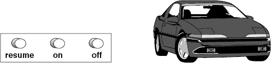
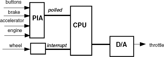
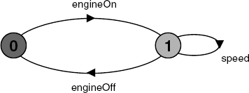
An automobile cruise control system has the following requirements. It is controlled by three buttons: resume, on and off (Figure 8.1). When the engine is running and on is pressed, the cruise control system records the current speed and maintains the car at this speed. When the accelerator, brake or off is pressed, the cruise control system disengages but retains the speed setting. If resume is pressed, the system accelerates or de-accelerates the car back to the previously-recorded speed. The hardware that supports the cruise control system is shown in Figure 8.2. It consists of a Parallel Interface Adapter (PIA) which records the actions of the buttons (on, off and resume), the brake (pressed), the accelerator (pressed) and the engine (on or off). The PIA is polled periodically every 100 msec to determine if any of these actions has occurred. A wheel revolution sensor generates interrupts for every wheel revolution in order to enable the system to calculate the current speed of the car. The cruise control system controls the car speed by setting the throttle of the car via a digital-to-analog converter (D/A).
The structure diagram and actions for the cruise control system shown in Figure 8.3 can be produced using the following design activities:
Identify the main actions and interactions of the system.
Identify and define the main processes of the system.
Identify the main properties of the system.
Structure the processes into a structure diagram.
These activities correspond to those used in previous chapters and are a refined version of those described above for producing a design architecture. The additional consideration of the properties is to ensure that the model includes those actions necessary for property checking, either as shared actions or actions internal to a process. For instance, we wish to ensure that the cruise control system is disengaged when the brake, accelerator or off button is pressed and that the throttle is eventually set. We discuss these properties later in the chapter.
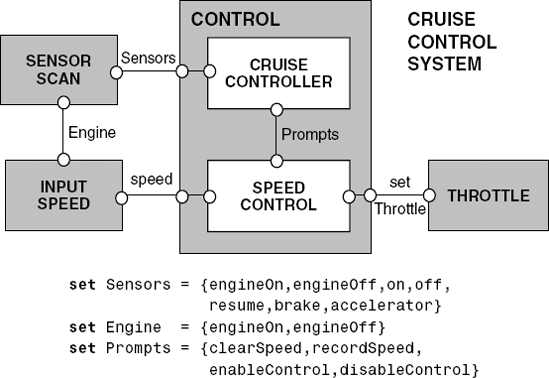
The main internal control for the cruise control system is provided by two processes: the cruise controller and the speed control. The interface to the external sensors and actuators is provided by the other three processes: sensor scan, input speed and throttle. The cruise controller receives the buttons, brake, accelerator and engine events from the sensor scan. The input speed process monitors the speed when the engine is on and provides the current speed readings to the speed control. Depending on the circumstances, cruise controller triggers clear or record the speed, and enable or disable the speed control. The speed control then sets the throttle accordingly. In this way, the sensor scan encapsulates (information hiding) the periodic process of scanning the sensors, the cruise controller encapsulates the decision as to when speed maintenance is activated, and the speed control encapsulates how to record and maintain speed.
As described in earlier chapters, it is beneficial to model and analyze the system design before embarking on implementation. Parallel composition can be used to compose the system from the model processes according to the composition hierarchy. Animation can be used for scenario checking, and automated model checking can be used for verification of safety and progress properties.
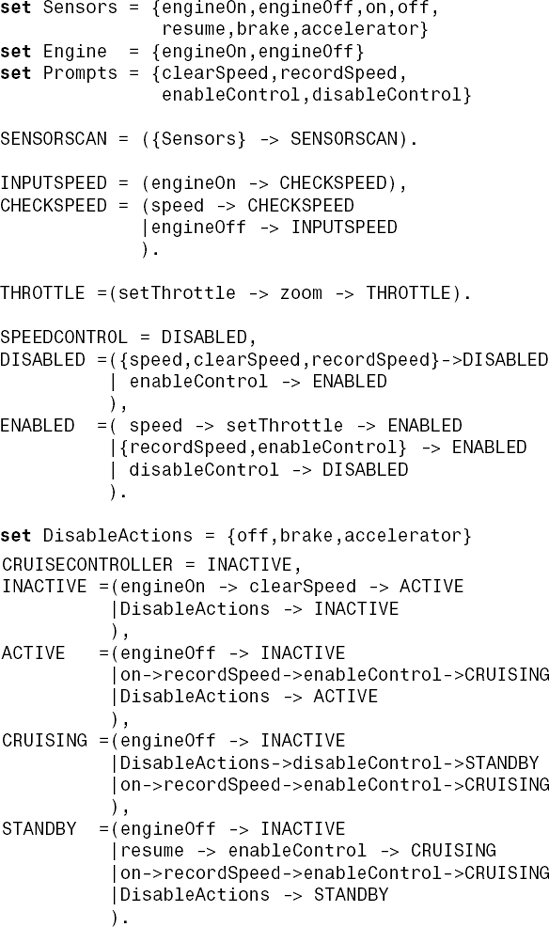
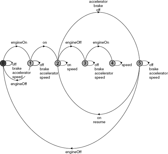
Each of the processes is defined in Figure 8.4. The sensors are repeatedly scanned; the input speed is repeatedly monitored when the engine is on; and, when the throttle is set, the car "zooms" off! Speed control is initially disabled. It clears and records the current speed setting, and, when it is enabled, it sets the throttle according to the current speed and the recorded speed. The behavior of the cruise controller is as follows. When the engine is switched on, clearSpeed is triggered and the cruise controller becomes active. When active, pressing the on button triggers recording the current speed and enables the speed control. The system is then cruising. Pressing the on button again triggers recording the new current speed and the system remains cruising. Pressing the off button, brake or accelerator disables the speed control and sets the system to standby. Switching the engine off at any time makes the system inactive.
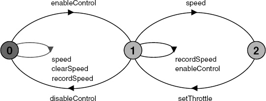
The corresponding LTS diagram for each of these processes can be inspected to check that the process does indeed model the desired, intuitive behavior. For example, the INPUTSPEED and SPEEDCONTROL LTS diagrams are shown in Figures 8.5 and 8.6 respectively. The LTS diagrams for SPEEDCONTROL and CRUISECONTROLLER are rather complex for easy inspection. At this stage it is often easier to use animation as a means of checking the general process behavior. For instance, the CONTROL subsystem (Figure 8.3) is composed as follows:
||CONTROL =(CRUISECONTROLLER||SPEEDCONTROL).
It can be animated to produce answers to the following questions:
- Is control enabled after the engine is switched on and the on button is pressed?
- Is control disabled when the brake is then pressed?
- Is control enabled when resume is then pressed?
The trace depicted on Figure 8.7 confirms this behavior: Note that the trace also illustrates that, when control is enabled, the speed input causes the throttle to be set, and when disabled, it does not. Although various scenarios help to improve our confidence in the adequacy of the model and its behavior, they do not provide an exhaustive check over all possible execution paths. To this end, we need to specify the safety properties of interest.
Safety checks are compositional in the sense that, if there is no violation at a subsystem level, then there cannot be a violation when the subsystem is composed with other subsystems. This is because, if the ERROR state of a particular safety property is unreachable in the LTS of the subsystem, it remains unreachable in any subsequent parallel composition which includes the subsystem. Safety checks can therefore be conducted directly on the subsystems which exhibit the behavior to be checked. The following guidelines are used when performing safety checks:
Note
Safety properties should be composed with the appropriate system or subsystem to which the property refers. In order that the property can check the actions in its alphabet, these actions must not be hidden in the system.
A safety property required of the CONTROL subsystem is as follows:
property CRUISESAFETY =
      ({DisableActions,disableControl}
                   -> CRUISESAFETY
      |{on,resume} -> SAFETYCHECK
      ),
SAFETYCHECK =
      ({on,resume} -> SAFETYCHECK
      |DisableActions -> SAFETYACTION
      |disableControl -> CRUISESAFETY
      ),
SAFETYACTION =(disableControl->CRUISESAFETY).
This property states that, if the CONTROL subsystem is enabled by pressing the on or resume buttons, then pressing the off button, the brake or the accelerator should result in the control system being disabled. The LTS diagram for this property is shown in Figure 8.8. We compose CRUISESAFETY with the CONTROL subsystem processes (Figure 8.3) as follows:
||CONTROL =
          (CRUISECONTROLLER||SPEEDCONTROL||CRUISESAFETY).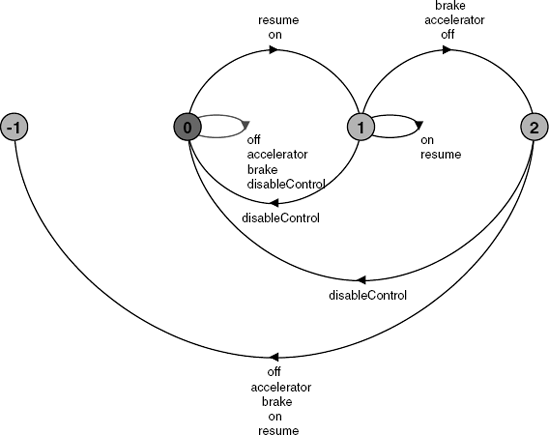
Safety analysis using LTSA produces the following violation:
Trace to property violation in CRUISESAFETY:
        engineOn
        clearSpeed
        on
        recordSpeed
        enableControl
        engineOff
        off
        off
This indicates a violation of the safety property in rather strange circumstances. If the system is enabled by switching the engine on and pressing the on button, and then the engine is switched off, it appears that the control system is not disabled, and disabling actions such as pressing the off button can be performed without the system being disabled. What if the engine were switched on again?
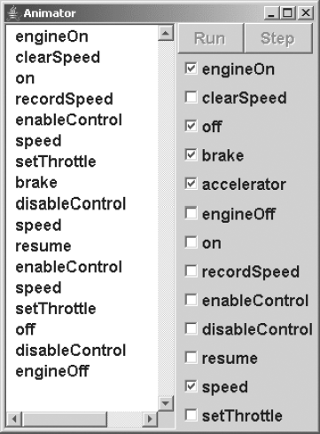
To investigate this, we can animate the control system to produce a trace as follows:
engineOn
       clearSpeed
       on
       recordSpeed
       enableControl
       engineOff
       engineOn
       speed
       setThrottle
       speed
       setThrottle
       ...
If the control system remains enabled, then the car will accelerate and zoom off when the engine is switched on again! This is a highly dangerous situation and one that should definitely be avoided.
To further investigate the circumstances which lead to this violation, we can also examine a minimized LTS diagram of the control system, without the safety property and in which only the Sensors and speed actions are visible:
||CONTROLMINIMIZED =(CRUISECONTROLLER||SPEEDCONTROL)
                       @ {Sensors,speed}.
Action hiding and minimization help to reduce the size of the diagram and make it easier to interpret. CONTROLMINIMIZED produces the LTS diagram in Figure 8.9 which clearly illustrates the situation where, once the engine is switched on again, the only action which can be performed is speed.
How can this potentially catastrophic situation be avoided? It is clear that control should be disabled when the engine is switched off. This would ensure that control is not enabled when the engine is switched on again. The required change to the CRUISECONTROLLER is as follows:
...
     CRUISING =(engineOff -> disableControl -> INACTIVE
               |DisableActions->disableControl->STANDBY
               |on->recordSpeed->enableControl->CRUISING
               ),
     ...
The CRUISESAFETY safety property did not include a check on the engine status. This must now be included to form an improved safety property:
propertyIMPROVEDSAFETY = ({DisableActions,disableControl,engineOff} -> IMPROVEDSAFETY |{on,resume} -> SAFETYCHECK ), SAFETYCHECK = ({on,resume} -> SAFETYCHECK |{DisableActions,engineOff} -> SAFETYACTION
|disableControl -> IMPROVEDSAFETY
),
SAFETYACTION =
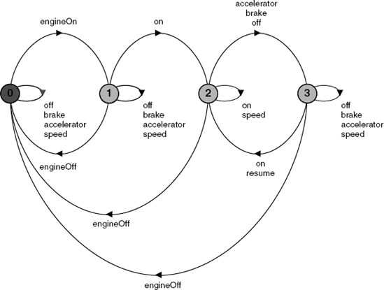
(disableControl -> IMPROVEDSAFETY).We can now repeat the analysis process as before. This time there are no safety violations. The minimized control system, as shown in Figure 8.10, is clearly reassuring. It indicates that the control system returns to the initial state when the engine is switched off.
We can now hide internal actions and proceed with the composition of that subsystem to form the complete cruise control system.
||CONTROL =
     (CRUISECONTROLLER||SPEEDCONTROL||IMPROVEDSAFETY)
        @ {Sensors,speed,setThrottle}.
||CRUISECONTROLSYSTEM =
(CONTROL||SENSORSCAN||INPUTSPEED||THROTTLE).Safety analysis using LTSA verifies that the CRUISECONTROLSYSTEM does not deadlock nor violate the revised safety property.
Progress checks are not compositional. Even if there is no violation at a subsystem level, there may still be a violation when the subsystem is composed with other subsystems. This is because an action in the subsystem may satisfy progress yet be unreachable when the subsystem is composed with other subsystems which constrain its behavior. Furthermore, action priority acts to discard lower priority action transitions in preference to higher priority ones. With parallel composition, higher priority actions may become unreachable thereby removing particular choices and requiring the restoration of the lower priority actions. We therefore conduct progress checks on the complete target system.
Note
Progress checks should be conducted on the complete target system after satisfactory completion of the safety checks.
We can now subject the cruise control system to progress checks, such as that the throttle is eventually set. In fact, the cruise control system is expected to be capable of operating repeatedly whenever the engine is switched on. Hence, we would expect that no action suffers starvation and that it is always that case that every action can eventually be chosen. We therefore perform a general progress test without specifying particular sets of progress actions. If this general test produces no violations, then we can be certain that there are no violations for any specific progress property. This is the case here, and progress analysis using LTSA on the CRUISECONTROLSYSTEM produces no violations.
However, progress analysis on the original, unrevised CRUISECONTROLSYSTEM, without the safety property, produces the following interesting progress violation:
Progress violation for actions:
     {accelerator, brake, clearSpeed,
     disableControl, enableControl, engineOff,
engineOn, off, on, recordSpeed, resume}
Trace to terminal set of states:
engineOn
clearSpeed
on
recordSpeed
enableControl
engineOff
engineOn
Cycle in terminal set:
speed
setThrottle
zoom
Actions in terminal set:
{setThrottle, speed, zoom}The trace confirms the interpretation that control is not disabled when the engine is switched off. Switching the engine on again leads to the terminal set in which the only actions permitted are speed input, the setting of the throttle and the resulting car zoom action. This can be clearly seen in Figure 8.9, except that there the actions setThrottle and zoom are hidden.
Further analysis of the model could be conducted to investigate system behavior under particular adverse conditions. For instance, we could employ action priorities to check progress when sensors are given high priority.
||SENSORSHIGH = CRUISECONTROLSYSTEM ≪ {Sensors}.No progress violations are detected. However, if the sensors are given a low priority:
||SENSORSLOW = CRUISECONTROLSYSTEM ≫ {Sensors}.then the speed action dominates and, on analysis, we obtain the following violation:
Progress violation for actions:
     {engineOn, engineOff, on, off, brake,
     accelerator, resume, setThrottle, zoom}
     Path to terminal set of states:
          engineOn
          tau
     Actions in terminal set:
     {speed}
This seems to indicate that the system may be sensitive to the priority of the action speed. This can be confirmed since, making speed a high priority is similar to making Sensors low, and making speed a low priority results in the following violation:
Progress violation for actions:
     {speed, setThrottle, zoom}
     Path to terminal set of states:
     Actions in terminal set:
     {engineOn, engineOff, on, off, brake,
     accelerator, resume}
Thus, models such as this can be used to indicate system sensitivities. If it is possible that erroneous situations detected in the model may occur in the implemented system, then the model should be revised to find a design which ensures that those violations are avoided. However, if it is considered that the real system will not exhibit this behavior, then no further model revisions are necessary. In this way, model interpretation and correspondence to the implementation are important in determining the relevance and adequacy of the model design and its analysis.
In the cruise control system, speed monitoring needs to be carefully controlled so that it neither dominates nor suffers from starvation. If we are confident that this can indeed be achieved in our implementation, then we need perform no further modeling. We now turn our attention to an implementation of the cruise control system, based on the model.
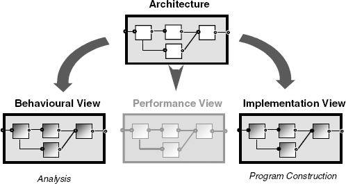
As mentioned, a design architecture describes the gross organization and global structure of the system in terms of its constituent components. In order to support behavior modeling and analysis, the architecture supports an elaborated view of its structure and the behavior of its components. We have used structure diagrams and FSP for this purpose. However, there are other forms of model and analysis that might be of interest (Figure 8.11). These too can be considered as views on the underlying structure, the elaboration adding those particular details of concern. For instance, another example of a view is a performance model, such as a queuing network.
Our particular concern after modeling is implementation. Note that even the implementation of the system should be considered as an elaboration of the underlying design architecture. Here the detail is the implementation of the component processes as threads and monitors. Maintaining consistency between these views is facilitated by the fact that the architectural structure is common to the different model views and the implementation.
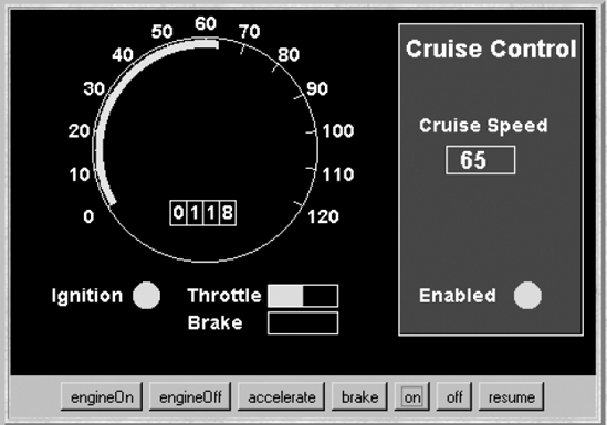
The program described in this section provides a simulation for the environment in which the cruise control implementation executes. Our simulation is a Java applet that provides buttons to simulate the actions of accelerating, braking and turning on and off both the engine and the cruise control system. Car speed is displayed on a simulated speedometer, which includes an odometer that registers the distance the car has progressed. A screen shot of the cruise control applet is depicted in Figure 8.12. The display shows the situation in which cruise control has been enabled to maintain the car at a steady speed of 65 miles per hour. The car has moved 1.18 miles since it was started.
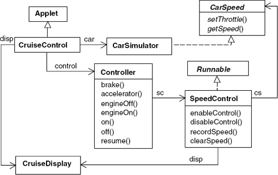
The class diagram for the cruise control program is shown in Figure 8.13. The classes Controller and SpeedControl implement the model processes CRUISECONTROLLER and SPEEDCONTROL. SpeedControl interacts with the car simulation provided by the class CarSimulator via the interface CarSpeed. This interface provides methods to set the throttle and to get the current speed at which the car is traveling. We have introduced this interface so that the classes implementing control are insulated from all the details of the simulation. The interface is listed in Program 8.1.
Example 8.1. CarSpeed interface.
public interfaceCarSpeed {publicint getSpeed();publicvoid setThrottle(double val); }
When a button is pressed, this event is passed by the Applet class to both the car simulator and the cruise controller using a method call. Thus, the Controller class provides a method corresponding to each button.
The implementation of Controller follows directly from the model process CRUISECONTROLLER. Each method modifies the control state and invokes speed control actions. The implementation is listed in Program 8.2. Controller is a passive entity; it always reacts to events and does not instigate them. It is implemented as a monitor with each model action becoming a synchronized method.
In contrast, SpeedControl, listed in Program 8.3, is an active entity. When it is enabled, a thread is created which periodically obtains the current car speed from the car simulator and sets the throttle so that the target cruising speed is maintained. The thread terminates when speed control is disabled. The run() method is also synchronized to prevent interference with the other methods of the class, and uses a wait with timeout to provide periodic execution. The wait(long) method of Java can be used to put the current thread to sleep until it is notified or the specified timeout period (in milliseconds) elapses.
Example 8.2. Controller class.
classController {final staticint INACTIVE = 0;// cruise controller statesfinal staticint ACTIVE = 1;final staticint CRUISING = 2;final staticint STANDBY = 3;privateint controlState = INACTIVE;// initial stateprivateSpeedControl sc; Controller(CarSpeed cs, CruiseDisplay disp) {sc=newSpeedControl(cs,disp);}synchronizedvoid brake(){if(controlState==CRUISING ) {sc.disableControl(); controlState=STANDBY; } }synchronizedvoid accelerator(){if(controlState==CRUISING ) {sc.disableControl(); controlState=STANDBY; } }synchronizedvoid engineOff(){if(controlState!=INACTIVE) { if (controlState==CRUISING) sc.disableControl(); controlState=INACTIVE; } }
synchronizedvoid engineOn(){if(controlState==INACTIVE) {sc.clearSpeed(); controlState=ACTIVE;} }synchronizedvoid on(){if(controlState!=INACTIVE){ sc.recordSpeed(); sc.enableControl(); controlState=CRUISING; } }synchronizedvoid off(){if(controlState==CRUISING ) {sc.disableControl(); controlState=STANDBY;} }synchronizedvoid resume(){if(controlState==STANDBY) {sc.enableControl(); controlState=CRUISING;} } }
SpeedControl is the first example we have met of a class that combines both synchronized access methods and a thread. We could have implemented it as two classes, a purely passive entity which encapsulated the state and setSpeed variables and an active entity with only a run() method. However, this would have been unnecessarily complex and would lead to additional methods to set and get the variables. As implemented, the class satisfactorily encapsulates the thread and the methods that control its execution.
This chapter has consolidated the model-based approach used in previous chapters. It has described the process of progressing from system requirements through modeling to programming. The main activities were identified, including system decomposition into a model structure and model elaboration, analysis and revision, if necessary. The stage at which properties are checked was also discussed. Safety properties can be checked on system or subsystem models as appropriate. Progress checks need to be performed on the overall system model. The mapping of a model structure into an implementation was also described. No particular design method is imposed. We advocate modeling in association with every design method. Modeling complements program design and is particularly useful when constructing concurrent programs.
Example 8.3. SpeedControl class.
classSpeedControlimplementsRunnable {final staticint DISABLED = 0;//speed control statesfinal staticint ENABLED = 1;privateint state = DISABLED;//initial stateprivateint setSpeed = 0;//target cruise control speedprivateThread speedController;privateCarSpeed cs;//interface to control speed of engineprivateCruiseDisplay disp; SpeedControl(CarSpeed cs, CruiseDisplay disp){this.cs=cs;this.disp=disp; disp.disable(); disp.record(0); }synchronizedvoid recordSpeed(){ setSpeed=cs.getSpeed(); disp.record(setSpeed); }synchronizedvoid clearSpeed(){if(state==DISABLED) {setSpeed=0;disp.record(setSpeed);} }synchronizedvoid enableControl(){if(state==DISABLED) { disp.enable(); speedController=newThread(this); speedController.start(); state=ENABLED; } }synchronizedvoid disableControl(){if(state==ENABLED) {disp.disable(); state=DISABLED;} }synchronizedpublicvoid run() {//the speed controller threadtry{while(state==ENABLED) { double error = (float)(setSpeed-cs.getSpeed())/6.0; double steady = (double)setSpeed/12.0; cs.setThrottle(steady+error);//simplified feed back controlwait(500); } }catch(InterruptedException e) {} speedController=null; }
A cruise control system for a car was used to illustrate the model-based design approach. This system was briefly introduced in Chapter 1 to motivate model-based design; it was dealt with in detail in this chapter, giving both the model details and an implementation in Java.
There are numerous books that describe software design methods and techniques, most of which include some form of informal modeling and reasoning to help in the design process. However, few use modeling in a rigorous fashion. One of the exceptions is Giorgio Bruno's book, Model-Based Software Engineering (1995), which uses Petri Net models. Another technique of interest is ROOM (Real-Time Object-Oriented Modeling) which combines a language for system structure with state machine models and is supported by the ObjecTime toolset for model execution (Selic, Gullekson and Ward, 1994). Statecharts (Harel, 1987) are supported by the STATEMATE (Harel, Lachover, Naamad, et al., 1990) software tool and are used for the design of reactive systems. A form of statecharts is also incorporated in the UML approach (Fowler and Scott, 1997; Booch, Rumbaugh and Jacobson, 1998), which recognizes the importance of modeling and provides a basketful of modeling notations and techniques. See http://www.uml.org/.
The car cruise control system used in this chapter is a simplified version of a real system. Actual systems do not disengage when the accelerator is pressed, but retain the speed setting and return the car to that speed when the accelerator is released.
The example of the car cruise control system is originally due to Grady Booch (1986) who adapted it from an exercise provided by P. Ward at the Rocky Mountain Institute for Software Engineering. Since then, it has been widely used as an example for the design of concurrent and real-time systems. For instance, Hassan Gomaa uses it as a case study in his book, Software Design Methods for Concurrent and Real-Time Systems (1993). Mary Shaw uses it as a common example for Comparing architectural design styles (1995).
The process of moving from requirements to models is recognized as far from easy. One approach to facilitate early model construction is to synthesize the behavior model using scenarios, such as Message Sequence Charts (MSCs; ITU, 1996). Each scenario is a partial story, describing how system components, the environment and users work concurrently and interact in order to provide system-level functionality. Synthesis is required to combine these so as to provide meaningful behavior. There are a number of approaches that generate statechart models from MSCs such as that of Koskimies, Männistö, Systä, et al. (1998) and Whittle and Schumann (2000). Harel and Kugler (2000) generate state-based behavior models using Live Sequence Charts, an extension to MSCs. Uchitel, Kramer and Magee (2003) have provided an approach to synthesize FSP models from MSCs and an approach to help perform model elaboration (Uchitel, Kramer and Magee, 2004). Extensions to the LTSA support this work.
The constructed models (whether by design or by synthesis) are intended to provide behavior that represents reality and the user requirements. In much the same way as the simulations are used to demonstrate the behavior of the Java implementations, so graphic animation of model behavior can be useful to help users understand and check model behavior before implementation. Magee, Pryce, Giannakopoulou, et al. (2000) have provided a technique in which LTS behavior models can drive graphical animations. An XML document maps between the model and the animation, implemented as a set of JavaBeans. An extension to LTSA supports this work. Another interesting approach is proposed by Harel and Marelly who propose the use of a mock user as a means for playing in scenarios into an LSC interpreter called the Play-Engine (Harel and Marelly, 2003).
8.1 Each of the rooms in a building has a control station for monitoring and controlling the environment. Each control station measures and displays the current temperature and humidity. For each room, the desired temperature and humidity is set by a pair of dials. If the current readings are outside the desired setting by more than 1%, then the station can control the heating or ventilation accordingly. A central operator station is able to request the current readings from any control station.
Outline the design structure of a room control station given that it is decomposed into the following processes: sensors, dials, heater – ventilator, display and controller. Provide a model for each process and check that the control station satisfies appropriate safety and progress properties.
Provide an implementation for the room control station.
8.2 A self-service gas station has a number of pumps for delivering gas to customers for their vehicles. Customers are expected to prepay a cashier for their gas. The cashier activates the pump to deliver gas.
Provide a model for a simple system with two customers and a gas station with one pump and a cashier. Include in the model a range for the different amounts of payment and that a customer is not satisfied (
ERROR) if the incorrect amount of gas is delivered:rangeA = 1..3 CUSTOMER = (prepay[a:A]->gas[x:A]-> if (x==a)thenCUSTOMERelseERROR ).Check the safety and progress properties for this system. Provide a simple Java implementation for the gas station system.
8.3 Extend the gas station model in exercise 8.2 to cater for N customers and M pumps. Specify and check a safety property, FIFO, which ensures that customers are served in the order in which they pay.