
A simulation scenario is an environment and one or more robot models that is used to prototype a control algorithm. The extent to which the environment reflects real-world conditions and limitations depends on the desired results from the simulation. If it is important that the exact code you use in the simulator can run on a real robot, then the simulated world and services must carefully model every important aspect of the real world. If the simulator is to be used only to prototype or demonstrate an algorithm, then real-world fidelity is less important.
In this chapter, you'll use the new Corobot robot entity from the last chapter in a simulation scenario that mimics the Seattle Robotics Society's Robo-Magellan competition. A description of the competition and the rules can be found at www.robothon.org/robothon/robo-magellan.php. Before the competition begins, a referee places cones on the course and then provides GPS coordinates to the contestants for their location. Robots start at a predetermined place and navigate to each cone, avoiding obstacles along the way. The challenges that the robots face are navigating over outdoor terrain, avoiding obstacles, and dealing with GPS signal problems.
In this simulation, you'll mainly focus on navigation and obstacle avoidance. You haven't built a GPS service yet so you'll use the robot position reported by the SimulatedQuadDifferentialDrive to mimic this capability.
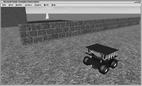
In the last chapter, you used the Corobot manifest to test the Corobot entity and its associated services. For this scenario, you'll define a new manifest that runs the Corobot services along with a referee service and the Robo-Magellan orchestration service. Figure 7-1 shows the completed Robo-Magellan scenario.
The first thing you'll need is a referee to set up the course and place the cones. In a scenario like this one, it is a good idea to separate the player functionality from the referee functionality. That way, the interface between the two is well defined and it is eventually easier to move the player service to an actual robot.
The referee service will be responsible for setting up all of the entities in the simulation environment, including the sky, sun, and ground entities as well as the obstacles in the world.
Instead of using DssNewService to create the referee service, you're going to copy Simulation Tutorial 1 from the SDK and modify it. Simulation Tutorial 1 is already set up to interact with the simulation environment and create environment entities, so it is already very close to what you want your referee to be. You can create a referee service using the following commands from the MRDS command prompt. The text that you type is shown in bold.
C:Microsoft Robotics Studio (1.5)ProMRDS>mkdirMyChapter7C:Microsoft Robotics Studio (1.5)ProMRDS>cd MyChapter7C:Microsoft Robotics Studio (1.5)ProMRDSMyChapter7>mkdir Referee C:Microsoft Robotics Studio (1.5)ProMRDSMyChapter7> copy ....samplessimulationtutorials utorial1*.* Referee ....samplessimulationtutorials utorial1AssemblyInfo.cs ....samplessimulationtutorials utorial1SimulationTutorial1.cs ....samplessimulationtutorials utorial1SimulationTutorial1.csproj ....samplessimulationtutorials utorial1SimulationTutorial1.csproj.user ....samplessimulationtutorials utorial1SimulationTutorial1.sln 5 file(s) copied.
Now you'll rename the files and change the namespace and contract identifier to make this service your own. Start by renaming the solution file and opening it from the command line as follows. Again, text that you type is shown in bold:
C:Microsoft Robotics Studio (1.5)ProMRDSMyChapter7Referee>renSimulationTutorial1.sln Referee.slnC:Microsoft Robotics Studio (1.5)ProMRDSMyChapter7Referee>Referee.sln
Use the following steps to make the Referee project:
Rename the SimulationTutorial1 project to Referee and rename
SimulationTutorial1.cstoReferee.csinside Visual Studio.Open
Referee.cs. Change the namespace fromRobotics.SimulationTutorial1toProMRDS.Simulation.MagellanReferee.Rename the
SimulationTutorial1class toMagellanRefereeand update theDisplayNameandDescriptionattributes.Change the contract identifier at the bottom of the file to
http://schemas.tempuri.org/2007/08/MagellanReferee.htm.Do a global replace of SimulationTutorial1 with MagellanReferee.
Open the solution properties and change the assembly name to
SimMagellanReferee.Y2007.M08, and change the default namespace toProMRDS.Simulation.MagellanReferee.The solution should now compile with no errors.
You don't have a manifest to run this service yet, so you'll use a different method to run it. Start a Dss Node at port 50000 without specifying a manifest:
C:Microsoft Robotics Studio (1.5)ProMRDSMyChapter7Referee>cd ......C:Microsoft Robotics Studio (1.5)>dsshost -p:50000 -t:50001* Service uri: [09/10/2007 08:12:33][http://msrs1:50000/directory] * Service uri: [09/10/2007 08:12:33][http://msrs1:50000/constructor/ef2ee88f- cf29-4052-9168-a6714fb53ae1] * No initial manifest supplied. [09/10/2007 08:12:34][http://msrs1:50000/ manifestloaderclient]
Open a browser window and navigate to http://localhost:50000. Select Control Panel from the left column and type referee in the Search box. You should see the new Magellan Referee service displayed with the DisplayName and Description you specified in the service. Click the Create button on the right and you should soon see the simulation window appear with the scene from Simulation Tutorial 1.
Now you'll modify the referee service to build a world for our scenario. Replace the contents of the PopulateWorld method with the following:
// Set up initial view
CameraView view = new CameraView();
view.EyePosition = new Vector3(-0.91f, 0.67f, −1f);
view.LookAtPoint = new Vector3(1.02f, 0.09f, 0.19f);
SimulationEngine.GlobalInstancePort.Update(view);
This sets the initial camera viewpoint to something convenient:
// Add another camera to view the scene from above
CameraEntity fromAbove = new CameraEntity(640, 480);
fromAbove.State.Name = "FromAbove";
fromAbove.Location = new xna.Vector3(4.3f, 20.59f, 0.86f);
fromAbove.LookAt = new xna.Vector3(4.29f, 18.26f, 0.68f);
fromAbove.IsRealTimeCamera = false;
SimulationEngine.GlobalInstancePort.Insert(fromAbove);
You also need to add a using statement, as shown in the following snippet, and a reference to Microsoft.Xna.Framework.DLL, as described in the previous chapter:
using xna = Microsoft.Xna.Framework;
Now add a second camera that looks at the whole scene from above. It is quick to switch to this camera using F8:
// Add a SkyDome.
SkyDomeEntity sky = new SkyDomeEntity("skydome.dds", "sky_diff.dds");
SimulationEngine.GlobalInstancePort.Insert(sky);

// Add a directional light to simulate the sun.
LightSourceEntity sun = new LightSourceEntity();
sun.State.Name = "Sun";
sun.Type = LightSourceEntityType.Directional;
sun.Color = new Vector4(1, 1, 1, 1);
sun.Direction = new Vector3(-0.47f, −0.8f, −0.36f);
SimulationEngine.GlobalInstancePort.Insert(sun);You use a typical sky and sun:
HeightFieldShapeProperties hf = new HeightFieldShapeProperties("height field",
    64, // number of rows
    10, // distance in meters, between rows
    64, // number of columns
    10, // distance in meters, between columns
    1, // scale factor to multiple height values
−1000); // vertical extent of the height field.
// create array with height samples
hf.HeightSamples = new HeightFieldSample[hf.RowCount * hf.ColumnCount];
for (int i = 0; i < hf.RowCount * hf.ColumnCount; i++)
{
hf.HeightSamples[i] = new HeightFieldSample();
hf.HeightSamples[i].Height = (short)(Math.Sin(i * 0.01));
}
// create a material for the entire field.
hf.Material = new MaterialProperties("ground", 0.8f, 0.5f, 0.8f);
// insert ground entity in simulation and specify a texture
SimulationEngine.GlobalInstancePort.Insert(
new HeightFieldEntity(hf, "FieldGrass.dds"));You use a ground plane substantially smaller than the standard flat ground used in the samples. This one is only 640 meters by 640 meters. Add the FieldGrass.dds texture to give the appearance of an open grassy field.
Now that you have the basics in place, you need to add a few barriers to make life interesting for your Corobot. The following code adds several walls and a cement tower. By grouping the barrier parameters in an array, it is easier to add additional barriers or define several different scene configurations. If you are trying to create a general-purpose navigation algorithm, you probably want to test it against several different barrier configurations.
Add the following code to create and insert the barriers just after the ground definition in PopulateWorld:
// create barriers
foreach (Barrier bar in Barriers)
{
    SingleShapeEntity wall =
        new SingleShapeEntity(
            new BoxShape(
                new BoxShapeProperties(
                    0,  // no mass makes a static shape
                    new Pose(),
                    bar.Dimensions)), // dimensions
                bar.Position);
    wall.State.Pose.Orientation = bar.Orientation;
    wall.State.Name = bar.Name;
    wall.State.Assets.DefaultTexture = bar.Texture;
    SimulationEngine.GlobalInstancePort.Insert(wall);
}
Add this class definition as a peer to the MagellanReferee class:
public struct Barrier
{
    public string Name;
    public Vector3 Position;
    public Vector3 Dimensions;
    public string Texture;
    public Quaternion Orientation;
    public Barrier(string name, Vector3 position, Vector3 dimensions,
        string texture, Quaternion orientation)
    {
        Name = name;
        Position = position;
        Dimensions = dimensions;
        Texture = texture;
        Orientation = orientation;
    }
}
Finally, add the following barrier definitions as a member variable at the top of the MagellanReferee class:
public Barrier[] Barriers = new Barrier[]
{
    // Name, Position, Dimensions, Texture, Orientation
    new Barrier("Wall0", new Vector3(0, 0, −4), new Vector3(4f, 0.8f, 0.1f),
        "BrickWall.dds", new Quaternion(0,0,0,1)),
    new Barrier("Wall1", new Vector3(-2.05f, 0, −3.05f),
        new Vector3(2f, 0.8f, 0.1f),
        "BrickWall.dds", Quaternion.FromAxisAngle(0, 1, 0, (float)(Math.PI / 2))),
    new Barrier("Wall2", new Vector3(1.41f, 0, 2.46f), new Vector3(6f, 0.8f, 0.1f),
        "BrickWall.dds", Quaternion.FromAxisAngle(0, 1, 0, (float)(Math.PI / 2))),
    new Barrier("Tower", new Vector3(5.58f, 2f, −0.59f), new Vector3(2f, 4f, 2f),
        "MayangConcrP.dds", new Quaternion(0,0,0,1)),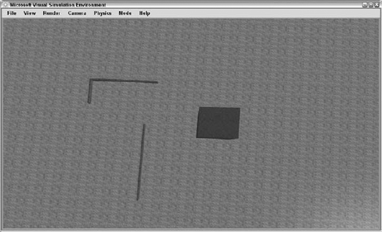
};It's a good time to run the service again to ensure that everything looks right. Run the service using the instructions in the previous section and switch to the FromAbove camera using F8. You should see a layout something like what is shown in Figure 7-2, which shows the Sim-Magellan world with a few walls and a tower.
The next step is to add some goals for your little robot to achieve. In the next section, you're going to define some special entities that know when they've been touched.
The SRS Robo-Magellan rules state that waypoints are marked by cones. The robot must approach and touch the cone without knocking it over. To help the referee service detect when a cone has been touched, you define a special kind of entity that uses a trigger shape. A trigger shape is a special physics shape that does not collide with other shapes. However, when another shape is inside its volume, it sends a notification. This type of shape is used to detect goals in the soccer simulation and to detect when the Sumo robots leave the sumo ring in the sumo simulation. Here, you'll use them to detect when the Corobot gets close enough to the traffic cone to touch it. The following method builds traffic cones with embedded trigger shapes:
private VisualEntity CreateTriggerCone(
    string name,
    Vector3 position)
{
    Vector3 dimensions = new Vector3(0.35f, 0.7f, 0.35f);
    position.Y += dimensions.Y / 2f;
    SingleShapeEntity triggerShape = new SingleShapeEntity(
        new BoxShape(
            new BoxShapeProperties(
                0,
                new Pose(),
                dimensions)),
        position);

    // used to receive a single trigger notification from this cone
Port<Shape> conePort = new Port<Shape>();
triggerShape.State.Name = name;
triggerShape.State.Assets.Mesh = "street_cone.obj";
triggerShape.BoxShape.State.Name = name;
triggerShape.BoxShape.State.Advanced =
new ShapeAdvancedProperties();
// make the box a trigger shape by adding a notification port
triggerShape.BoxShape.State.Advanced.IsTrigger = true;
triggerShape.BoxShape.State.Advanced.TriggerNotificationPort =
conePort;
triggerShape.State.MassDensity.Mass = 0;
triggerShape.State.MassDensity.Density = 0;
Activate(Arbiter.Receive<Shape>(false, conePort,
delegate(Shape sh)
{
Console.WriteLine("Cone " + name + " was triggered.");
}
));
return triggerShape;
}You use a SingleShapeEntity as your trigger entity. The dimensions are specified to match the size of the traffic cone model included with the SDK. The Y position is adjusted so that the cone isn't halfway embedded in the ground. A port that receives Shape objects is also defined to receive notifications from the trigger shape. The entity is given a name and the street_cone.obj mesh is specified for it to use. Now it gets interesting. You allocate a ShapeAdvancedProperties class and then set the IsTrigger flag to true. You specify the port you just created as the TriggerNotificationPort. You also give the entity a mass of 0, which makes it a static entity. The physics engine will not move the entity and it expects the entity to have the same position and orientation for the duration of the simulation.
Finally, you activate a one-time receiver to listen on the conePort for any shape that intersects the trigger shape. It is a one-time receiver because the trigger shape sends a notification to the port once each frame for as long as a shape intersects. You're really only interested in being notified the first time this happens. When the port receives a Shape message, a message prints to the console indicating that the referee has ruled that the cone has been successfully touched. The entity is returned so that it can be inserted in the simulator.
Now you have a way to define goals for the robot. You also need a way to transfer the coordinates of the cones to the robot. You'll take advantage of the service architecture and the ease with which state can be passed between services by defining the state of the referee service to hold the list of cones in the environment. Add the following state class definition as a peer to the MagellanReferee service:
#region State
/// <summary>
/// Magellan Referee State
/// </summary>
[DataContract()]
public class MagellanRefereeState
{
    [DataMember]
    public Vector3[] Cones;
}
#endregion
Just to keep things simple, the state will consist of an array of positions that identify the location of each cone. Add a member variable to hold the service state just after the _engineStub port definition in the MagellanReferee service:
[InitialStatePartner(Optional = true, ServiceUri = "Magellan.Referee.config.xml")]
private MagellanRefereeState _state = new MagellanRefereeState();
By defining an InitialStatePartner, it is possible to change the configuration of the cones simply by changing the optional config file Magellan.Referee.config.xml. If no configuration file is specified, the state needs to be initialized with default values. Add a call to ValidateState at the beginning of the Start method to initialize the state if necessary. The ValidateState method generates a default state as follows:
private void ValidateState()
{
    if (_state == null)
        _state = new MagellanRefereeState();

    if ((_state.Cones == null) || (_state.Cones.Length == 0))
    {
        // default state
        _state.Cones = new Vector3[]
        {
            new Vector3(0, 0, −5),
            new Vector3(10, 0, 4),
            new Vector3(-3, 0, 2)
        };
    }
}
Here, three traffic cone positions are specified. You may change this to add more as you improve your navigation algorithm.
Now you can add code to the PopulateWorld method to add these cones to your environment. It is important to add these objects and the barrier objects after the ground has been added to the simulation environment. Otherwise, it is possible that the timing will be just right for the cones to be inserted and start falling before the ground is inserted:
for (int coneCount = 0; coneCount < _state.Cones.Length; coneCount++)
    SimulationEngine.GlobalInstancePort.Insert(
        CreateTriggerCone(
          "Cone" + coneCount.ToString(),
          _state.Cones[coneCount]));
Give each cone a unique name and create one cone for each position in the state. Now that the service has state, you have a reason to implement the GetHandler as a method on the MagellanReferee class:
[ServiceHandler(ServiceHandlerBehavior.Concurrent)]
public virtual IEnumerator<ITask> GetHandler(Get get)
{
    get.ResponsePort.Post(_state);
    yield break;
}
Change the MagellanRefereeOperations port definition to add the Get operation:
[ServicePort]
public class MagellanRefereeOperations: PortSet<DsspDefaultLookup, DsspDefaultDrop, Get>
{
}

public class Get: Get<GetRequestType, PortSet<MagellanRefereeState, Fault>>
{
}
Other services can now query for the location of the cones simply by sending a Get request to the referee service. You'll need to add an additional using statement at the top of the SimMagellan.cs file to resolve the Fault type:
using W3C.Soap;
The only remaining task for the referee is to create the star of the show, the CorobotEntity. Add the following code at the end of the PopulateWorld method:
// create a Corobot
SimulationEngine.GlobalInstancePort.Insert(
    new corobot.CorobotEntity("Corobot", new Vector3(0, 0, 0)));
To tell the service what a CorobotEntity is, add the following using statement at the top of the file, and add a reference to the Corobot service. Remember to set Copy Local and Specific Version to false in the properties of the Corobot service reference:
using corobot = ProMRDS.Simulation.Corobot;
Compile and run the referee service again to verify that you have sky, grass, walls, tower, cones, and a nice-looking Corobot. Your opening scene should look something like Figure 7-1 at the beginning of this chapter. If there are some differences in the colors, it may be because your graphics card is only able to use version 1.1 shaders. If so, try changing the quality setting in the Graphics Settings dialog box (from the Rendering menu) to see if your card will support higher-quality rendering.
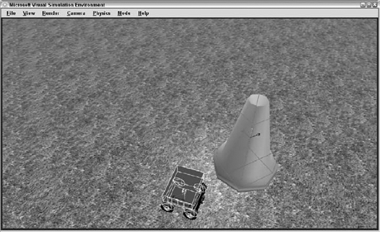
Switch to the combined physics and visual view by pressing F2 several times or by selecting it from the Render menu. You will notice that trigger shapes are drawn in violet on the screen. In Figure 7-3, they are the gray lines surrounding the cone.
At last, you get to the service that implements the robot behavior. In this section, you'll generate a service that does not communicate directly with the simulator but instead gets its information about the simulated world from other services. You'll use the Manifest Editor to generate a manifest to run all of the services, and add a small Windows Forms user interface to enable user control and debugging of the service. You'll also use a very simple image processing method to enable the robot to see the cones in the environment.
Use the following steps to generate the SimMagellan service and to specify its references and ports:
Use
DssNewServiceto generate the service. The command line is simpler because you are not implementing an alternate contract. The followingdssnewservicecommand is a single line but is shown on two lines due to formatting limitations. The text you type is shown in bold:C:Microsoft Robotics Studio (1.5)ProMRDS>
cd myChapter7C:Microsoft Robotics Studio (1.5)ProMRDSMyChapter7>dssnewservice /s:"SimMagellan" /n:"ProMRDS.Simulation.Magellan" /year:"07" /month:"08"C:Microsoft Robotics Studio (1.5)ProMRDSMyChapter7>cd SimMagellanC:Microsoft Robotics Studio (1.5)ProMRDSMyChapter7>SimMagellan.csprojEdit the
DisplayNameandDescriptionattributes inSimMagellan.csto better describe the SimMagellan service.Add the following
usingstatements at the top of theSimMagellan.csfile:using Microsoft.Robotics.PhysicalModel.Proxy; using drive = Microsoft.Robotics.Services.Drive.Proxy; using quadDrive = ProMRDS.Simulation.QuadDifferentialDrive.Proxy; using webcam = Microsoft.Robotics.Services.WebCam.Proxy; using referee = ProMRDS.Simulation.MagellanReferee.Proxy; using irsensor = Microsoft.Robotics.Services.AnalogSensor.Proxy;
Add references to the following DLLs to the project. Notice that we are using the Proxy versions of each service DLL.
RoboticsCommonand its Proxy are referenced because you make use of proxy and non-proxy types in theMicrosoft.Robotics.PhysicalModelnamespace. You reference proxy versions of the referee, the IR service, and the drive service.SimulationCommon.dllis referenced to pick up the types inMicrosoft.Robotics.Simulation. Finally, you referenceSystem.Drawing.dllbecause you will be using some bitmap types. Don't forget to set theCopy LocalandSpecific Versionproperties tofalseon each DLL reference.RoboticsCommon RoboticsCommon.proxy SimMagellanReferee.Y2007.M08.Proxy.dll SimulatedIR.Y2007.M08.Proxy.dll SimulatedQuadDifferentialDrive.Y2007.M08.Proxy.dll SimulationCommon.dll System.Drawing.dll
Now add the following ports to the
SimMagellanclass. The service uses these ports to communicate with the other services:// used to communicate with the QuadDifferentialDrive [Partner( "QuadDrive", Contract = quadDrive.Contract.Identifier, CreationPolicy = PartnerCreationPolicy.UseExisting, Optional = false)] quadDrive.QuadDriveOperations _quadDrivePort = new quadDrive.QuadDriveOperations(); // used to communicate with the DifferentialDrive alternate [Partner( "Drive", Contract = drive.Contract.Identifier, CreationPolicy = PartnerCreationPolicy.UseExisting, Optional = false)] drive.DriveOperations _drivePort = new drive.DriveOperations(); // used to communicate with the webcam on the Corobot [Partner( "robotcam", Contract = webcam.Contract.Identifier, CreationPolicy = PartnerCreationPolicy.UseExisting, Optional = false)] webcam.WebCamOperations _cameraPort = new webcam.WebCamOperations();// used to communicate with the referee service [Partner( "referee", Contract = referee.Contract.Identifier, CreationPolicy = PartnerCreationPolicy.UseExisting, Optional = false)] referee.MagellanRefereeOperations _refereePort = new referee.MagellanRefereeOperations(); // used to communicate with the IR sensor service [Partner( "irsensor", Contract = irsensor.Contract.Identifier, CreationPolicy = PartnerCreationPolicy.UseExisting, Optional = false)] irsensor.AnalogSensorOperations _irSensorPort = new irsensor.AnalogSensorOperations(); irsensor.AnalogSensorOperations _irNotifyPort = new irsensor.AnalogSensorOperations();
Verify that the service will compile. You can run it but it doesn't do much yet. The next step is to define a manifest that will run all the services you need and link them together properly.
The Manifest Editor is a new tool provided with the 1.5 release of Microsoft Robotics Developer Studio. It is an easy alternative to hand-editing confusing XML manifests. Any tool that enables you to avoid hand-editing .xml files is a good thing.
You'll use it here to set up the manifest for your scenario because it consists of several services.
Run the Manifest Editor by clicking Start
Click the SimMagellan service in the left column and drag it to the center column. Release the mouse button. The SimMagellan service is now listed as part of the manifest and its five partners are listed below it. You'll resolve those in just a minute.
Add the following services by dragging them into an empty area of the center column:
SimulatedQuadDifferentialDriveService
Simulated Webcam
Simulated Magellan Referee
Simulated IR Distance Sensor
Resolve the SimMagellan service's
QuadDrivepartner by selecting the SimulatedQuadDifferentialDriveService listed in the center column and then dragging it to theQuadDrivepartner box under the SimMagellan service. This sets up the manifest so that the SimulatedQuadDifferentialDrive service is paired with the_quadDrivePortin the SimMagellan service.Drag the SimulatedQuadDifferentialDrive service from the center column to the Drive partner under the SimMagellan service to associate this service with the
_drivePortin the SimMagellan service.Resolve the other three partners under the SimMagellan service by dragging the appropriate service in the center column to the partner box.
Now you need to specify a simulation entity partner for the services that need one. Select
SimulatedQuadDifferentialDriveServiceby clicking it. Now right-click it to bring up a context menu and select Add a Partnership. In the dialog box that appears, enter Entity (without quotes) in the Name box. Enter the SimulationEngine service contract in the Namespace box:http://schemas.microsoft.com/robotics/2006/04/simulation.htmland press OK. A new Partner box labeled Entity appears under theSimulatedQuadDifferentialDriveServicebox. Select this partner by clicking it, and a Simulation Entity box appears in the Properties column on the right side of the screen. Type the name of the simulation entity that partners with the QuadDrive service in the form of a URI:http://localhost/Corobot. That entity name appears in the Partner box under theSimulatedQuadDifferentialDriveServicein the manifest.Add an entity partner to the Simulated IR Distance Sensor service with the name
http://localhost/Corobot_frontIR, just as in step 6.Add an entity partner to the SimulatedWebcam service with the name
http://localhost/Corobot_cam, just as you did in steps 6 and 7.Save the manifest with the name MySimMagellan. The Manifest Editor will create a directory called
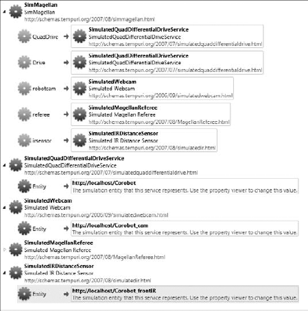
MySimMagellancontaining the manifestMySimMagellan.manifest.xml. Your manifest should look similar to the one shown in Figure 7-4.Run the manifest by clicking Run

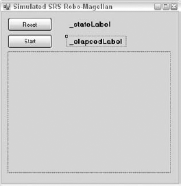
It is very helpful to retrieve the state of any running service using a web browser, but sometimes you need a real user interface to debug or control a service. In this section, you'll add a Windows Forms user interface to display information about the SimMagellan service and to reset and start it. Robotics Tutorial 4, provided with the MRDS SDK, explains how to add a simple Windows Form to your service. This example shows more aspects of using a Windows Form in your service.
For this part of the project, you can either create the form yourself or copy the SimMagellanUI.* files from the Chapter7SimMagellan directory into the MyChapter7SimMagellan project. To create your user interface, follow these steps:
Add a new Windows Form file to your SimMagellan project called
SimMagellanUI.cs.Add a Reset button called
_resetButton. Figure 7-5 shows the controls on the SimMagellan UI Form that you're creating.Add a Start button called
_startButtonto the form.Add a
PictureBoxcontrol called_cameraImageto the form. Give it a size of 320 × 240.Add a
labelcontrol called _stateLabel.Add a
labelcontrol called_elapsedLabel.Change the title of the main window to SRS Robo-Magellan and add an icon if you like.
With the form created and the controls placed, you're ready to hook up the communication between the service and the form. Windows Forms controls may only be accessed by the thread that created them. This is a problem in the MRDS environment because there are no guarantees regarding which thread is running a particular piece of code.
Fortunately, MRDS provides a set of code that makes it easy for services to interact with Windows Forms. Add the following using statement to your SimMagellan.cs file along with a reference to the Ccr.Adapters.WinForms DLL:
using Microsoft.Ccr.Adapters.WinForms;
The first thing you'll do is establish a way for the form to pass events back to the service. This is easily done by defining a port that can receive messages from the form. The FromWinformEvents class defined in the following snippet defines a port that can receive a single message type, a FromWinformMsg. This message contains a command, an array of string parameters, and an arbitrary object reference. The meaning of the string parameters and the object depends on the command in the message.
#region WinForms communication

public class FromWinformEvents: Port<FromWinformMsg>
{
}

public class FromWinformMsg
{
    public enum MsgEnum
    {
        Loaded,
        Reset,
        Test,
        Start,
    }

    private string[] _parameters;
    public string[] Parameters
    {
        get { return _parameters; }
        set { _parameters = value; }
    }

    private MsgEnum _command;
    public MsgEnum Command
    {
        get { return _command; }
        set { _command = value; }
    }

    private object _object;
    public object Object
    {
        get { return _object; }
        set { _object = value; }
}
public FromWinformMsg(MsgEnum command, string[] parameters)
{
_command = command;
_parameters = parameters;
}
public FromWinformMsg(
MsgEnum command, string[] parameters, object objectParam)
{
_command = command;
_parameters = parameters;
_object = objectParam;
}
}
#endregionAdd the definitions of the FromWinformEvents class and the FromWinformMsg class to SimMagellanTypes.cs. Add a member variable to the SimMagellanUI class in SimMagellan.cs to receive messages from the Windows Form:
// This port receives events from the user interface
FromWinformEvents _fromWinformPort = new FromWinformEvents();
Now add a handler to the interleave to listen for messages from this new port in the Start method, just after the call to base.Start:
// Add the winform message handler to the interleave
MainPortInterleave.CombineWith(new Interleave(
    new TeardownReceiverGroup(),
    new ExclusiveReceiverGroup
    (
        Arbiter.Receive<FromWinformMsg>(
            true, _fromWinformPort, OnWinformMessageHandler)
    ),
    new ConcurrentReceiverGroup()
));
Instantiating a Windows Form is as simple as posting a message to the WinFormsServicePort defined by the CCR Winforms Adapter immediately after the interleave is set:
// Create the user interface form
WinFormsServicePort.Post(new RunForm(CreateForm));
RunForm is a class defined by the Winforms Adapter that takes a delegate as a parameter. The delegate is responsible for instantiating the form. The adapter code starts a thread that is dedicated to the form and then uses that thread to call the passed delegate. In this case, the delegate is a method on the SimMagellan class called CreateForm:
// Create the UI form
System.Windows.Forms.Form CreateForm()
{
    return new SimMagellanUI(_fromWinformPort);
}
You pass a reference to _fromWinformPort so that the form can use this port to pass back messages.
In the SimMagellanUI.cs file, you need to modify the SimMagellanUI class constructor to accept this parameter:
FromWinformEvents _fromWinformPort;

public SimMagellanUI(FromWinformEvents EventsPort)
{
    _fromWinformPort = EventsPort;
    InitializeComponent();
    _fromWinformPort.Post(
        new FromWinformMsg(FromWinformMsg.MsgEnum.Loaded, null, this));
}
The constructor keeps a reference to this port in _fromWinformPort and then initializes itself and sends a message back to the SimMagellan service to indicate that the form is now loaded.
Back in the SimMagellanUI class, add a handler for this message as follows:
SimMagellanUI _magellanUI = null;

// process messages from the UI Form
void OnWinformMessageHandler(FromWinformMsg msg)
{
    switch (msg.Command)
    {
        case FromWinformMsg.MsgEnum.Loaded:
            // the windows form is ready to go
            _magellanUI = (SimMagellanUI)msg.Object;
            break;

    }
}
When the Loaded message is received from the form, the service stores a reference to the form. This reference sends commands to the form.
Now you have established a way for the service to send commands and information to the form, and a way for the form to notify the service when user interface events occur.
You should take this opportunity to compile your SimMagellan service. Run it using the Manifest Editor as described in the section "Creating a Manifest with the Manifest Editor." The form associated with the SimMagellan service should appear when the service runs.
The next task is to give the robot an objective and a way to accomplish that objective. In this case, the objective is fairly clear. Your robot needs to ask the referee service where the cones are, and then it needs to navigate to each one and touch it.
An common method for defining a behavior like this is to set up a state machine. A state machine defines several states that represent a current situation for the robot. Certain events from the outside world can change the state. For example, the robot could have a Wander state whereby it is moving about the environment trying to get closer to a cone. When the IR sensor detects an obstacle nearby, the state may change from Wander to AvoidCollision, and the SimMagellan service will issue commands to the Drive service to move the robot away from the obstacle. When the obstacle has been avoided, the robot state will change back to Wander.
In this section, you'll set up the state machine for the robot and define the actions it takes in each of these states. It should be stated again that this behavior algorithm is by no means optimal. You've done a lot of work in this chapter to set up the scenario and you'll have a basic behavior implemented to demonstrate it, but the whole purpose of the exercise is to provide a way to refine the behavioral algorithm and to prototype new ideas.
You will be defining the following states. Each state listed here includes a brief description of the associated robot behavior:
NotSpecified: This is the initial state of the state machine. The robot does nothing at all in this state. It moves to the
Resetstate when the Reset button is pressed.Reset: In this state, the robot begins processing camera frames, displaying the elapsed time on the user interface. It retrieves a list of the cone positions from the Referee service and subscribes to the IR Sensor service for notifications. It enables the robot drive and moves the robot to its initial position. After all this is done, the state is changed to
Ready.Ready: The
Readystate is much like theNotSpecifiedstate. The robot does nothing at all. It changes to theWanderstate when the Start button is pressed.Wander: This is the main state of the robot while it navigates in the environment. In this state, the robot checks the last image received from the camera. If it detects a cone, then the state changes to
Approach. Otherwise, the robot uses a method calledGetHappinessto determine its next move. This method returns a "happiness" value that is calculated according to the robot's proximity to a cone that has not yet been touched. The idea is that the robot seeks higher and higher levels of happiness by navigating closer to a cone until it is close enough to see it and move directly toward it. There is some degree of randomness associated with the movement in this state because set patterns of movement can sometimes result in endless cycles. If the happiness level in the current position is greater than the happiness level in the previous position, the robot continues on its current course. Otherwise, it backs up to its previous position, adjusts its heading randomly, and then proceeds forward in the next direction. This behavior is repeated until the robot moves into theApproachstate or theAvoidCollisionstate.AvoidCollision: This state is entered when the IR Sensor service notifies the SimMagellan service that the distance measurement has changed and is less than one meter. In this state, the robot backs away a quarter meter, turns 90 degrees to the left, and then moves forward one meter. The robot then returns to the
Wanderstate.Approach: When the robot sees a cone, it enters the
Approachstate. In this state, the robot checks the distance from the IR sensor. If it is less than a meter, it goes to theFinalApproachstate. Otherwise, it checks the position of the cone in the camera frame, adjusts its heading to head straight for the cone, and then moves forward a quarter meter and repeats the process.FinalApproach: By the time the robot reaches this state, it is closer than one meter to the cone and pointed more or less straight at the cone. In this mode, the robot no longer relies on the camera image but only on the IR distance data. It waits for another IR distance reading and then slowly moves that distance toward the cone. Then it marks the cone as having been touched, after which that cone is no longer considered in the
GetHappinessmethod. After this is done, the robot enters theBackAwaystate.BackAway: The purpose of this state is to allow the robot to back away from the cone it just touched. It moves backward one meter and then turns 45 degrees to the left and resumes wandering. If all of the cones are touched, then the robot enters the
Finishedstate.Finished: At this point, the robot has accomplished its objective. The elapsed time is no longer incremented on the user interface, and the robot spins in circles to show that it is victorious. It doesn't leave this state unless the Reset button is pushed to restart the scenario.
Now that you understand the states and behaviors defined in the last section, you are ready to write the code to implement this state machine. The current robot state will be stored in the SimMagellan service state. Replace the definition of the SimMagellanState class in SimMagellanTypes.cs as follows:
[DataContract]
public enum ModeType
{
    NotSpecified = 0,
    Reset,
    Ready,
    Wander,
    AvoidCollision,
    Approach,
    FinalApproach,
    BackAway,
    Finished
}

/// <summary>
/// The SimMagellan State
/// </summary>
[DataContract()]
public class SimMagellanState
{
    [DataMember]
    public ModeType CurrentMode;
}
Add a BehaviorLoop method to the SimMagellan class:
// keep track of the time to finish
DateTime _startTime;
DateTime _endTime;

const float _rotateSpeed = 0.3f;
const float _driveSpeed = 0.5f;
bool _iteratorsStarted = false;

IEnumerator<ITask> BehaviorLoop()
{
    bool driveCommandFailed = false;
    ModeType previousMode = ModeType.NotSpecified;
    while (true)
    {
        driveCommandFailed = false;

        if (previousMode != _state.CurrentMode)
        {
            // update the UI
            WinFormsServicePort.FormInvoke(
                delegate()
                {
                    _magellanUI.SetCurrentState(
                        _state.CurrentMode.ToString());
                }
            );
        }
        previousMode = _state.CurrentMode;
        switch (_state.CurrentMode)
        {
            case ModeType.NotSpecified:
            case ModeType.Ready:
                yield return Arbiter.Receive(
                    false,
                    TimeoutPort(100),
                    delegate(DateTime timeout) { });
                break;
        }
    }
}
For the previous block of code, the _driveSpeed and _rotateSpeed constants are used to set the default speed for the robot to drive and turn. _startTime and _endTime are used to keep track of how much time has elapsed since the Start button was pressed. The first thing the BehaviorLoop method does is to initialize the state to NotSpecified. It then enters an endless loop to continually process the robot's behavior. Each time through the loop, it checks whether the mode has changed. If it has, you call the SetCurrentState API on the SimMagellanUI class to display the current state on the user interface. Notice that you do this by posting a FormInvoke message on the WinFormsServicePort with a delegate containing the code you want to run. This code is always executed on the Windows Forms thread.
A switch statement is used to take a specific action based on the current state. You've already implemented a behavior for two states: NotSpecified and Ready. The behavior for these states is to wait 100 ms and then break out of the switch statement to go through the loop again. The only way to break out of one of these states is to click the Reset or Start buttons.
Add a SpawnIterator call at the end of the Start method so that the BehaviorLoop begins after the service has initialized:
SpawnIterator(BehaviorLoop);
The next step is to add methods in the SimMagellanUI class that will process these button clicks and send a notification to the SimMagellan service. Add the following two event handlers to the _resetButton and _startButton controls in the SimMagellanUI class:
private void _startButton_Click(object sender, EventArgs e)
{
    _fromWinformPort.Post(
        new FromWinformMsg(FromWinformMsg.MsgEnum.Start, null));
}

private void _resetButton_Click(object sender, EventArgs e)
{
    _fromWinformPort.Post(
        new FromWinformMsg(FromWinformMsg.MsgEnum.Reset, null));
    _startButton.Enabled = true;
}
You also need to hook the Click event for each of the buttons in SimMagellanUI.designer.cs as shown here. If you double-click on the buttons in the designer, this is done for you:
this._resetButton.Click += new System.EventHandler(this._resetButton_Click);
this._startButton.Click +=new System.EventHandler(this._startButton_Click);
Each of these handlers posts a message to the _fromWinformPort to tell the SimMagellan service that a button was clicked. While you're modifying the SimMagellanUI class, you may as well add the methods that update the current state and the elapsed time labels on the form:
public void SetCurrentState(string state)
{
    _stateLabel.Text = "State: " + state;
}

public void SetElapsedTime(string time)
{
    _elapsedLabel.Text = time;
}
Back in the SimMagellan class, add the following two case statements to the OnWinformMessageHandler to process these messages from the user interface:
case FromWinformMsg.MsgEnum.Reset:
    _state.CurrentMode = ModeType.Reset;
    break;

case FromWinformMsg.MsgEnum.Start:
    if(_state.CurrentMode == ModeType.Ready)
    {
        _startTime = DateTime.Now;
        _state.CurrentMode = ModeType.Wander;
    }
    break;
At this point, you should be able to compile the SimMagellan service and run it. When you click the Reset button, the State label should change to Reset.
Now you're ready to implement the behavior for the Reset state. Add the following case statement to the BehaviorLoop method:
case ModeType.Reset:
    {
        if (!_iteratorsStarted)
        {
            // start processing camera frames
            SpawnIterator<DateTime>(DateTime.Now, ProcessFrame);

            // start displaying elapsed time
            SpawnIterator<DateTime>(DateTime.Now, UpdateElapsedTime);

            _irSensorPort.Subscribe(_irNotifyPort);

            MainPortInterleave.CombineWith(new Interleave(
                new TeardownReceiverGroup(),
                new ExclusiveReceiverGroup(),
                new ConcurrentReceiverGroup
                (
                    Arbiter.Receive<irsensor.Replace>(
                        true,
                        _irNotifyPort,
                        IRNotifyReplaceHandler)
                )
            ));

            // we don't want to start additional iterators if the reset
            // button is pushed to restart the scenario
            _iteratorsStarted = true;
        }

        yield return Arbiter.Choice(_refereePort.Get(),
            delegate(referee.MagellanRefereeState state)
                { SetWaypoints(state); },
            delegate(Fault f) { }
            );

        _drivePort.EnableDrive(true);
        _drivePort.SetDriveSpeed(0, 0);
        _quadDrivePort.SetPose(
            new quadDrive.SetPoseRequestType(
                new Microsoft.Robotics.PhysicalModel.Proxy.Pose()));
        _state.CurrentMode = ModeType.Ready;

        break;
    }
Several things are going on here to get our little robot ready to start. First, you start the iterator methods that process the camera frames and update the elapsed time. You'll look at those in just a bit.
Next, you subscribe to notifications from the IR Sensor service. This means that each time the value of the front IR sensor changes, the _irNotifyPort receives a message with the new IR sensor service state. You add a handler to the interleave to handle this message.
Next, you post a Get message to the Referee service to get a list of cone positions. You keep track of these positions in a list of waypoints. A waypoint holds the position of a cone and a Boolean indicating whether the cone has been visited.
Finally, the drive is enabled and a SetPose message is sent to the _quadDrivePort to move the robot back to the starting position. The default Pose that is sent has a position of (0,0,0) and an orientation with no rotations.
Let's look at the SetWaypoints method first because it is the simplest:
private void SetWaypoints(referee.MagellanRefereeState state)
{
    foreach (Vector3 location in state.Cones)
        _waypoints.Add(new Waypoint(location));
}
The _waypoints member is just a list of Waypoint objects, which are defined as follows:
class Waypoint
{
    public Vector3 Location;
    public bool Visited;

    public Waypoint(Vector3 location)
    {
        Location = location;
        Visited = false;
    }
}
Declare _waypoints in the SimMagellan class as follows:
List<Waypoint> _waypoints = new List<Waypoint>();
Now you need to add the UpdateElapsedTime method. This method runs in an endless loop to determine the elapsed time depending on the current state. If the string representing the time has changed since the last time it has been displayed, it is sent to the UI with a call to _magellanUI.SetElapsedTime:
private IEnumerator<ITask> UpdateElapsedTime(DateTime timeout)
{
    string previous = string.Empty;
    while (true)
    {
        string newString = string.Empty;

        switch (_state.CurrentMode)
{
case ModeType.NotSpecified:
case ModeType.Ready:
case ModeType.Reset:
newString = string.Format("Elapsed: {0}:{1:D2}", 0, 0);
break;
case ModeType.Wander:
case ModeType.Approach:
case ModeType.FinalApproach:
case ModeType.BackAway:
{
TimeSpan elapsed = DateTime.Now—_startTime;
newString = string.Format("Elapsed: {0}:{1:D2}",
elapsed.Minutes, elapsed.Seconds);
break;
}
case ModeType.Finished:
{
TimeSpan elapsed = _endTime—_startTime;
newString = string.Format("Elapsed: {0}:{1:D2}",
elapsed.Minutes, elapsed.Seconds);
break;
}
}
if (newString != previous)
{
previous = newString;
// update the UI
WinFormsServicePort.FormInvoke(
delegate()
{
_magellanUI.SetElapsedTime(newString);
}
);
}
yield return Arbiter.Receive(
false, TimeoutPort(100), delegate { });
}
}The handler for the IR Distance Sensor aborts any current drive requests by posting an AllStop message to the _drivePort if the distance reading is less than one meter. Any DriveDistance or RotateDegrees operations in progress will return a Fault response, which aborts the current operation and causes the state machine to begin processing the AvoidCollision state:
void IRNotifyReplaceHandler(irsensor.Replace replace)
{
    if (replace.Body.RawMeasurement < 1f)    // closer than 1 meter
    {
        if (_state.CurrentMode == ModeType.Wander)
{
// stop dead in our tracks, abort DriveDistance and
// RotateDegrees in progress
_drivePort.AllStop();
_state.CurrentMode = ModeType.AvoidCollision;
}
}
}The last method to implement to make the Reset state complete is ProcessFrame. Because this method is a little more complicated, we'll take a closer look at it.
The topic of robot vision and navigating using vision could fill many books, and it is still a largely unsolved problem. Fortunately, your requirements are simple, so the vision algorithm doesn't need to be very complicated.
Vision algorithms can be very difficult to debug, so it is useful to have the SimMagellan service provide some feedback about what it is doing. The ProcessFrame method is quite simple by itself. It sends a request to the SimulatedWebCam service each 200 milliseconds:
private IEnumerator<ITask> ProcessFrame(DateTime timeout)
{
    while (true)
    {

        yield return Arbiter.Choice(
            _cameraPort.QueryFrame(),
            ValidateFrameHandler,
            DefaultFaultHandler);

        yield return Arbiter.Receive(
            false, TimeoutPort(200), delegate { });
    }
}
The DefaultFaultHandler simply logs the fault in case the camera was unable to return a frame:
void DefaultFaultHandler(Fault fault)
{
    LogError(fault);
}
The camera frame response is handled by the ValidateFrameHandler. This handler checks the timestamp on the camera frame and discards the image if it is older than one second. This prevents the robot from making decisions based on stale data in case something delays the camera from sending frames. The frame is analyzed with the ProcessImage method and is then sent to the user interface form along with the analysis results. The analysis results are used to draw a rectangle around recognized objects:
private void ValidateFrameHandler(webcam.QueryFrameResponse cameraFrame)
{
    try
    {
        if (cameraFrame.Frame != null)
        {
            DateTime begin = DateTime.Now;
            double msFrame =
                begin.Subtract(cameraFrame.TimeStamp).TotalMilliseconds;

            // Ignore old images!
            if (msFrame < 1000.0)
            {
                _imageProcessResult = ProcessImage(
                    cameraFrame.Size.Width,
                    cameraFrame.Size.Height,
                    cameraFrame.Frame);

                WinFormsServicePort.FormInvoke(
                    delegate()
                    {
                        _magellanUI.SetCameraImage(
                            cameraFrame.Frame, _imageProcessResult);
                    }
                );
            }
        }
    }
    catch (Exception ex)
    {
        LogError(ex);
    }
}
Add an ImageProcessResult member variable to the SimMagellan service and add the definition for the ImageProcessResult class:
// latest image processing result
ImageProcessResult _imageProcessResult = null;
 [DataContract]
public class ImageProcessResult
{
    [DataMember]
    public int XMean;

    [DataMember]
    public float RightFromCenter;

    [DataMember]
    public int YMean;
[DataMember]
public float DownFromCenter;
[DataMember]
public int Area;
[DataMember]
public DateTime TimeStamp;
[DataMember]
public int AreaThreshold = 50*50;
}The definition of the SetCameraImage method on the SimMagellanUI class is fairly simple. It creates an empty bitmap and attaches it to the PictureBox control on the form if one doesn't already exist. It locks the bitmap and then copies the bits from the camera frame. After unlocking the bitmap, it draws a rectangle around the area identified by the ImageProcessResult if the area of the result is large enough. It also draws a small crosshair in the center of the area. The presence or absence of the white rectangle is a good way to know when the vision algorithm detects an object:
public void SetCameraImage(byte[] frame, ImageProcessResult result)
{
    if (_cameraImage.Image == null)
        _cameraImage.Image = new Bitmap(
            320, 240,
            System.Drawing.Imaging.PixelFormat.Format24bppRgb);

    Bitmap bmp = (Bitmap)_cameraImage.Image;
    System.Drawing.Imaging.BitmapData bmd = bmp.LockBits(
        new Rectangle(0, 0, bmp.Width, bmp.Height),
        System.Drawing.Imaging.ImageLockMode.ReadWrite,
        bmp.PixelFormat);

    System.Runtime.InteropServices.Marshal.Copy(
        frame, 0, bmd.Scan0, frame.Length);

    bmp.UnlockBits(bmd);

    if (result.Area > result.AreaThreshold)
    {
        int size = (int)Math.Sqrt(result.Area);
        int offset = size / 2;
        Graphics grfx = Graphics.FromImage(bmp);
        grfx.DrawRectangle(
            Pens.White,
            result.XMean—offset,
            result.YMean—offset, size, size);
        grfx.DrawLine(
            Pens.White,
            result.XMean—5,
            result.YMean, result.XMean + 5, result.YMean);
        grfx.DrawLine(
            Pens.White,
            result.XMean,
result.YMean—5, result.XMean, result.YMean + 5);
}
_cameraImage.Invalidate();
}The last method that should be explained is the ProcessImage function. Many vision algorithms do sophisticated edge detection or gradient processing. This simple algorithm is actually adapted from the vision algorithm shipped as part of the MRDS Sumo Competition package. It simply scans through the pixels and keeps track of how many pixels meet some criteria. It also keeps track of the average position of those pixels in the image:
private ImageProcessResult ProcessImage(
int width, int height, byte[] pixels)
{
    if (pixels == null || width < 1 || height < 1 || pixels.Length < 1)
        return null;

    int offset = 0;
    float threshold = 2.5f;
    int xMean = 0;
    int yMean = 0;
    int area = 0;

    // only process every fourth pixel
    for (int y = 0; y < height; y += 2)
    {
        offset = y * width * 3;
        for (int x = 0; x < width; x += 2)
        {
            int r, g, b;

            b = pixels[offset++];
            g = pixels[offset++];
            r = pixels[offset++];

            float compare = b * threshold;
            if((g > compare) && (r > compare))
            {
                // color is yellowish
                xMean += x;
                yMean += y;
                area++;

                // debug coloring
                pixels[offset—3] = 255;
                pixels[offset—2] = 0;
                pixels[offset—1] = 255;
            }
            offset += 3;    // skip a pixel
        }
    }

    if (area > 0)
{
xMean = xMean / area;
yMean = yMean / area;
area *= 4;
}
ImageProcessResult result = new ImageProcessResult();
result.XMean = xMean;
result.YMean = yMean;
result.Area = area;
result.RightFromCenter =
(float)(xMean—(width / 2)) / (float)width;
result.DownFromCenter =
(float)(yMean—(height / 2)) / (float)height;
return result;
}In this case, you know that the cones are yellow and that there are few, if any, other yellow objects in the scene. Therefore, you look for pixels that have a red and green component much larger than their blue component. As an additional debug aid, the code colors the identified pixels magenta. This is a great debugging aid because it enables you to see exactly which pixels are being considered in the result.
To aid in performance, you need only analyze every other pixel in the image in width and height. The area is incremented by four for every pixel that is identified because each pixel represents four pixels in the image.
This is a good time to compile your service again and observe the behavior of the vision algorithm. Run your mySimMagellan manifest. When all the services have started, click the Reset button on the SimMagellan user interface form. The form should begin displaying the image from the Corobot camera updated five times per second. You can start the Simulation Editor by pressing F5 in the simulation window. Select the Corobot entity in the upper-left pane and select its position property in the lower-left pane. Drag the Corobot with the left mouse button while holding down the Ctrl key. Move the Corobot so that it is facing one of the street cones and verify that the image processing algorithm correctly identifies the object, and colors every other yellow pixel magenta, as in Figure 7-6.
Most of the time, the robot navigates and discovers the environment using the Wander state. The behavior in this state is intentionally left a little "fuzzy" and random. In part, this acknowledges that in the real world, positional data from GPS sensors has varying and limited accuracy. It is also an intentional way to deal with cyclical behavior. It is common to see a robot with a very specific objective get into a cycle in which it heads straight for its objective only to hit an obstacle, take a quick detour, and then head again straight for its objective and hit the same obstacle again. Without some random behavior and the ability to switch objectives, the robot may never complete the course. Once again, though, be aware that none of these behaviors is optimal and there is a lot of room for improvement and experimentation.
This is the code for the Wander case in the BehaviorLoop switch statement:
case ModeType.Wander:
    {
        // check to see if we have identified a cone
        if (_imageProcessResult != null)
        {
            if (_imageProcessResult.Area >
                _imageProcessResult.AreaThreshold)
            {
                // we have a cone in the crosshairs
                _state.CurrentMode = ModeType.Approach;
                continue;
            }
        }

        quadDrive.DriveDifferentialFourWheelState quadDriveState = null;
        yield return Arbiter.Choice(_quadDrivePort.Get(),
            delegate(quadDrive.DriveDifferentialFourWheelState state)
            {
                quadDriveState = state;
            },
            delegate(Fault f) { }
        );

        if (quadDriveState == null)
            continue;

        double distance;
        double degrees;
        float currentHappiness = GetHappiness(quadDriveState.Position);
        if (currentHappiness > _previousHappiness)
        {
            // keep going in the same direction
            distance = 0.25;
            degrees = 0;
        }
        else
        {
            // back up and try again
            if(!driveCommandFailed)
yield return Arbiter.Choice(
_drivePort.DriveDistance(-0.25, _driveSpeed),
delegate(DefaultUpdateResponseType response) { },
delegate(Fault f) { driveCommandFailed = true; }
);
distance = 0.25;
// choose an angle between −45 and −90.
degrees = (float)_random.NextDouble() * −45f—45f;
// restore happiness level of previous position
_previousHappiness = _previousPreviousHappiness;
}
if (degrees != 0)
{
if (!driveCommandFailed)
yield return Arbiter.Choice(
_drivePort.RotateDegrees(degrees, _rotateSpeed),
delegate(DefaultUpdateResponseType response) { },
delegate(Fault f) { driveCommandFailed = true; }
);
}
if (!driveCommandFailed)
yield return Arbiter.Choice(
_drivePort.DriveDistance(distance, _driveSpeed),
delegate(DefaultUpdateResponseType response) { },
delegate(Fault f) { driveCommandFailed = true; }
);
_previousPreviousHappiness = _previousHappiness;
_previousHappiness = currentHappiness;
break;
}The first thing the robot does is check whether the image processing method has found a cone. If it has, it changes to the Approach state. If not, it continues wandering for another step.
Next, find out where the robot is by asking the SimulatedQuadDifferentialDrive for the current position. In the real world, this would be a GPS service and the coordinates returned would be latitude and longitude. Then, you call GetHappiness to find out how happy the robot is in this position. Being near a cone makes the robot very happy.
If the robot's happiness in this location is greater than the happiness in its previous location, it decides to continue moving in this direction for another quarter meter. Otherwise, it backs up to the previous position and picks a new direction. The new direction is a random angle between 245 and 290 degrees.
Notice that the code checks whether any previous drive command failed while processing this state. If it did, that could mean that the IR Distance Sensor service sent a notification that the robot is closer than one meter to an obstacle, terminating the current command by sending an AllStop message. In this case, you want to abort the current state processing and get back to the top of the switch statement because the state has probably changed to AvoidCollision.
As mentioned earlier, the GetHappiness method is a way for the robot to be motivated to move in the right direction. When it is moving toward a cone, happiness increases. Moving away from a cone decreases its happiness and causes it to rethink its life decisions. This is a fuzzy way of encouraging the robot to go in the right direction. The code is fairly simple:
float _previousHappiness = 0;
float _previousPreviousHappiness = 0;
Random _random = new Random();

float GetHappiness(Vector3 pos)
{
    float happiness = 0;
    for(int i=0; i<_waypoints.Count; i++)
    {
        if (_waypoints[i].Visited)
            continue;

        float dx = (pos.X—_waypoints[i].Location.X);
        float dz = (pos.Z—_waypoints[i].Location.Z);
        float distance = (float)Math.Sqrt(dx * dx + dz * dz);

        float proximity = 50f—Math.Min(distance, 50f);
        if(proximity > 40f)
            proximity = proximity * proximity;

        happiness += proximity;
    }
    return happiness;
}
The code only considers waypoints that have not been visited yet. As soon as a waypoint is visited, it no longer makes the robot happy and it moves on to other pursuits, not unlike some people. The happiness function is simply the sum of the proximity to each nonvisited cone, squared. If a cone is more than 50 meters away, then it doesn't contribute to the happiness function.
When the vision processing algorithm detects that the robot is close enough to a cone to exceed the area threshold, the robot enters the Approach state, which has the following implementation:
case ModeType.Approach:
    {
        float IRDistance = −1f;

        // get the IR sensor reading
        irsensor.Get tmp = new irsensor.Get();
        _irSensorPort.Post(tmp);
        yield return Arbiter.Choice(tmp.ResponsePort,
            delegate(irsensor.AnalogSensorState state)
            {
                if (state.NormalizedMeasurement < 1f)
IRDistance = (float)state.RawMeasurement;
},
delegate(Fault f) { }
);
if (IRDistance >= 0)
{
// rely on the IR sensor for the final approach
_state.CurrentMode = ModeType.FinalApproach;
break;
}
if ((_imageProcessResult == null) ||
(_imageProcessResult.Area <
_imageProcessResult.AreaThreshold))
{
// lost it, go back to wander mode
_state.CurrentMode = ModeType.Wander;
continue;
}
float angle = _imageProcessResult.RightFromCenter * −2f * 5f;
float distance = 0.25f;
if (!driveCommandFailed)
yield return Arbiter.Choice(
_drivePort.RotateDegrees(angle, _rotateSpeed),
delegate(DefaultUpdateResponseType response) { },
delegate(Fault f) { driveCommandFailed = true; }
);
if (!driveCommandFailed)
yield return Arbiter.Choice(
_drivePort.DriveDistance(distance, _driveSpeed),
delegate(DefaultUpdateResponseType response) { },
delegate(Fault f) { driveCommandFailed = true; }
);
break;
}In the Approach state, the code first checks whether the robot is within one meter of an obstacle, assuming that the obstacle is a cone. If so, the robot moves to the FinalApproach state. If the robot no longer has the cone in its sights, it goes back to Wander mode. Otherwise, it needs to get closer.
You use the _imageProcessResult.RightFromCenter value to determine how far right or left the robot needs to turn in order to center the cone in the camera frame. The numbers used here were arrived at through experimentation. The code then adjusts the angle and moves forward a quarter meter. Eventually, the robot gets close enough to the cone to enter FinalApproach mode or it loses sight of the cone and goes back into Wander mode until the cone is sighted again.
The FinalApproach state has the following implementation:
case ModeType.FinalApproach:
    {
        // rely on the IR sensor for the remainder of the cone approach
        float IRDistance = −1f;

        // get the IR sensor reading
        irsensor.Get tmp = new irsensor.Get();
        _irSensorPort.Post(tmp);
        yield return Arbiter.Choice(tmp.ResponsePort,
            delegate(irsensor.AnalogSensorState state)
            {
                if (state.NormalizedMeasurement < 1f)
                    IRDistance = (float)state.RawMeasurement;
            },
            delegate(Fault f) { }
        );

        if (IRDistance < 0)
        {
            // go back to the visual approach
            _state.CurrentMode = ModeType.Approach;
            break;
        }
        if (!driveCommandFailed)
            yield return Arbiter.Choice(
                _drivePort.DriveDistance(IRDistance, 0.2),
                delegate(DefaultUpdateResponseType response) { },
                delegate(Fault f) { driveCommandFailed = true; }
            );

        // mark the cone as touched
        quadDrive.DriveDifferentialFourWheelState quadDriveState = null;
        yield return Arbiter.Choice(_quadDrivePort.Get(),
            delegate(quadDrive.DriveDifferentialFourWheelState state)
            {
                quadDriveState = state;
            },
            delegate(Fault f) { }
        );

        if (quadDriveState != null)
        {
            for (int i = 0; i < _waypoints.Count; i++)
            {
                float dx = (quadDriveState.Position.X -
                            _waypoints[i].Location.X);
                float dz = (quadDriveState.Position.Z -
                            _waypoints[i].Location.Z);
                float distance = (float)Math.Sqrt(dx * dx + dz * dz);
                if (distance < 1f)
_waypoints[i].Visited = true;
}
}
_state.CurrentMode = ModeType.BackAway;
break;
}In the FinalApproach state, you rely only on the IR Distance Sensor. The robot makes a reading of the distance to the cone and then moves exactly that far forward. In the real world, where IR distance readings are not always exact, it would probably be necessary to make smaller steps toward the cone. When the robot moves close enough to the cone to touch it, you ask the drive for the robot's position and then determine which cone it was that the robot touched, marking it as touched. Then the robot goes into the BackAway state that moves it away from the cone.
The BackAway state simply moves the robot away from the cone it just touched and points it in a different direction:
case ModeType.BackAway:
    {
        // back away and turn around
        if (!driveCommandFailed)
            yield return Arbiter.Choice(
                _drivePort.DriveDistance(-1, _driveSpeed),
                delegate(DefaultUpdateResponseType response) { },
                delegate(Fault f) { driveCommandFailed = true; }
            );

        if (!driveCommandFailed)
            yield return Arbiter.Choice(
                _drivePort.RotateDegrees(45, _rotateSpeed),
                delegate(DefaultUpdateResponseType response) { },
                delegate(Fault f) { driveCommandFailed = true; }
            );

        _state.CurrentMode = ModeType.Finished;
        for (int i = 0; i < _waypoints.Count; i++)
        {
            if (!_waypoints[i].Visited)
            {
                _state.CurrentMode = ModeType.Wander;
                _previousHappiness = 0;
                _previousPreviousHappiness = 0;
                break;
            }
        }

            if (_state.CurrentMode == ModeType.Finished)
{
// all the cones have been visited
_endTime = DateTime.Now;
}
break;
}After that, it checks whether all the cones have been touched. If so, the robot enters the Finished state. Otherwise, it returns to the Wander state to find more cones.
The Finished state simply causes the robot to spin around in wild celebration until you click the Reset button to try the scenario again:
case ModeType.Finished:
    if (!driveCommandFailed)
        yield return Arbiter.Choice(
            _drivePort.RotateDegrees(180, _rotateSpeed),
            delegate(DefaultUpdateResponseType response) { },
            delegate(Fault f) { driveCommandFailed = true; }
        );
    break;
The only state that hasn't been described yet is the AvoidCollision state. Right now, this state does the same thing regardless of where the obstacle lies. It would be a great improvement if the robot did more discovery to determine the direction to drive to actually avoid the obstacle, rather than blunder around:
case ModeType.AvoidCollision:
    {
        // back away
        if (!driveCommandFailed)
            yield return Arbiter.Choice(
                _drivePort.DriveDistance(-0.25, _driveSpeed),
                delegate(DefaultUpdateResponseType response) { },
                delegate(Fault f) { driveCommandFailed = true; }
            );

        // turn left
        if (!driveCommandFailed)
            yield return Arbiter.Choice(
                _drivePort.RotateDegrees(90, _rotateSpeed),
                delegate(DefaultUpdateResponseType response) { },
                delegate(Fault f) { driveCommandFailed = true; }
            );

        _state.CurrentMode = ModeType.Wander;
// move forward
if (!driveCommandFailed)
yield return Arbiter.Choice(
_drivePort.DriveDistance(1, _driveSpeed),
delegate(DefaultUpdateResponseType response) { },
delegate(Fault f) { driveCommandFailed = true; }
);
break;
}As you can see from the implementation, when the robot detects an impending collision, it backs up a quarter meter, turns 90 degrees to the left, changes to Wander mode, and then drives forward one meter.
Add the state implementations just discussed to your code, along with the GetHappiness method and its associated variables, and your SimMagellan service is complete.
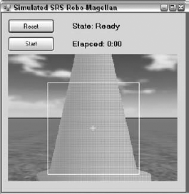
Once you click Reset and Start, the service runs itself. You will probably have to move the MainCamera around a bit to keep the Corobot in view, and you'll definitely want to be watching the SimMagellan user interface form to see the results of the image processing and the current state of the robot. The elapsed time gives you a good measure of your algorithm's efficiency, although the same algorithm can have radically different execution times as a result of very small variations in the robot's behavior. Each time you enhance the robot behavior, measure the elapsed time of a few runs to determine the amount of improvement you have achieved.
Don't forget that you can use the Simulation Editor to select the Corobot entity and move it around in the environment. This can come in handy if it happens to hit a wall on the edge and flip over or if you just want to see how it handles a particular approach to a cone.
There are several things you can do with this simulation scenario to make it more like the actual SRS Robo-Magellan competition. For one thing, very few robot drives can report back on their actual position in the world. You should implement a simulated GPS entity and associated service that returns the position of the robot in latitude and longitude. Such a simulated service should probably also provide a way to model areas of poor reception in the world so that the navigation algorithm can handle these properly.
Another improvement to this simulation would be to change the happiness function to make the robot traverse the cones in a particular order. In the current simulation, the order in which the robot visits the cones is unimportant. One simple way to make the obstacle avoidance more efficient is to add waypoints with a negative happiness to the list each time an obstacle is encountered. This would keep the robot from moving toward an area where there is a known obstacle.
Finally, the obstacles in the environment are currently fairly simple. It is fairly easy to reconfigure the environment in the Referee service or to even have several canned environments that can be easily selected. A good navigation algorithm should be able to handle a variety of environments.
Congratulations! Between this chapter and the last one, you have covered quite a bit of territory, not to mention nearly 3500 lines of code.
In this chapter, you built on the entities and services defined in the last chapter to create a complete scenario. A Referee service initialized the environment with trigger cones, barriers, and a single Corobot. Finally, you defined the Robo-Magellan orchestration service, complete with a Windows Forms user interface and a robot behavior model sufficient to navigate the course.
Having conquered the world of wheeled robots for the time being, you'll now move on to robotic arms and articulated robots in the next chapter.