
The Microsoft Visual Programming Language (VPL) can be used to implement general-purpose programs that have nothing to do with robotics, but because it is part of the Microsoft Robotics Developer Studio SDK, this chapter focuses on robotic applications.
First, the relationship between VPL activities and DSS services is explained, and you'll learn how to compile a diagram into a C# service implementation. Next you'll learn how to associate an activity with a specific service. Simple examples are provided that demonstrate how to control actuators and read data from sensors.
More complicated examples are presented in Chapter 12.
A VPL activity can represent a DSS service. As explained in Chapter 3, a service implements a specific contract by supporting a number of operations on its main port. A service may also implement an alternate contract and its associated operations on a separate port. The VPL activity that represents the service has inputs for all of the operations on the main port and any alternate ports.
You know from the previous chapter that an activity may have more than one action associated with it. Each action has its own set of inputs and outputs. Each action associated with an activity corresponds to an operation supported by the service. For example, when you connect a wire to the input of the SimpleDialog service, three possible actions are supported: AlertDialog, PromptDialog, and ConfirmDialog. If you look at the implementation of the simple dialog in samplesMiscUtilityDialogDialogTypes.cs, the DialogOperations class has operations defined for DsspDefaultLookup, DsspDefaultDrop, Alert, Prompt, and Confirm. The DisplayName attribute for the Alert class is "AlertDialog," and this Alert operation corresponds to the Alert action in the SimpleDialog activity. The inputs and outputs for this action are also defined by the Alert class. The input message for this operation is an AlertRequest class that contains a single DataMember string with the DisplayName attribute of "AlertText." The output or response message is a DefaultSubmitResponseType or a Fault.
When you define an activity in a VPL diagram, you are really defining a DSS port. Each action in the activity corresponds to an operation on that port. The inputs and outputs of each action correspond to the input and response messages of that operation. The logic implemented in the diagram for a particular action defines what happens in the handler for that particular input message. VPL is really just a graphical way of describing the DSS model of service ports and messages.
As you might imagine, the notification outputs of an action correspond to notifications from a service, and a connection from a notification output to an input pin on a service corresponds to that service subscribing to the notifications. Not only do activities within a diagram correspond to ports within services, the top-level diagram itself represents a single service.
Note that VPL doesn't enable any service functionality that is not already achievable using C# or some other .NET language and programming directly to the DSS model. However, nearly anyone who has written code to define services and pass messages between them will agree that VPL is a much simpler and more concise way of specifying the same functionality.
Now that you know that VPL diagrams represent the DSS model of services, ports, and messages, you might wonder if it is possible to convert services to diagrams and whether it is also possible to convert a diagram to a service. Of course, the answer is yes; otherwise, this would be a very short section.
In the case of converting services to diagrams, you have already seen how this works in Chapter 10. All of the activities in the Services toolbox represent services that are present on the current machine. Each time one of these services is dragged onto the diagram, an activity icon is displayed that represents the service. All of the information about the service is available on the input and output pins showing the various actions (operations) supported by the service port and the data passed in the input and response messages of each operation.
The more interesting case is converting a diagram to a service. When you press F5 or F10 to run a service, VPL has an interpreter, which executes the diagram. Another way to execute the diagram is to compile it into a service and then run that service.
You can compile a diagram into a service by clicking Build
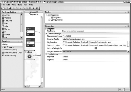
A number of other properties affect how the service will be compiled. You can display these properties by clicking the Diagrams item in the Project toolbox. The properties are displayed in the Properties toolbox under the CompileSetting heading. The compile properties for the 8-CustomActivity (in order) VPL diagram are shown in Figure 11-1.
The following properties are supported:
NamespacePrefix: This prefix is prepended to every namespace in the project. It enables you to use namespaces in the generated service that correspond to your particular organization or group.
ContractPrefix: This prefix is used as the first part of the contract identifier for the service. For example, the contract identifier constructed for this service is derived from the ContractPrefix, the current date, and the name of the main diagram:
http://schemas.tempuri.org/2007/12/customactivityorder/customactivityinorder.html.KeyLocation: This is the location of the key file used for signing the service code.
SourceLocation: This is the directory where the source code for the service will reside.
IncludeDebugInfo: This determines whether the service is compiled with debug information present.
TargetFramework: This specifies whether the service targets .NET v2.0 or the .NET Compact Framework v2.0.
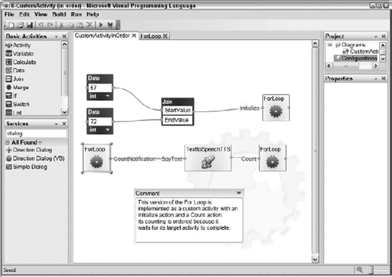
Open the 8-CustomActivity (in order) project in the chapter10 directory and compile it by selecting the item on the Build menu. A compiled version of this diagram is in ProMRDSchapter11CompiledCustomActivity. The source diagram is shown in Figure 11-2.
The files generated by the VPL compilation are as follows:
CustomActivityInOrderService.cs
CustomActivityInOrderTypes.cs
CustomActivityorder.csproj
CustomActivityorder.csproj.user
CustomActivityorder.manifest.xml
ForLoopService.cs
ForLoopTypes.cs
VPL has taken the .mvpl filename and converted it to a valid project name: CustomActivityorder.csproj. The associated .user file specifies a reference path and debug actions that cause the manifest to be executed when F5 is pressed. This project contains everything needed to build the target service.
VPL has also generated a manifest that can be used to run the target service. The source code for the manifest shows all of the services that are executed:
<?xml version="1.0"?>
<Manifest xmlns:customactivityinorder=
"http://schemas.tempuri.org/2007/12/customactivityorder/customactivityinorder.html" xmlns:texttospeech="http://schemas.microsoft.com/2006/05/texttospeech.html"
xmlns:this="urn:uuid:996d98f0-d63b-40a1-bb40-312c8cb2fac3"
xmlns:dssp="http://schemas.microsoft.com/xw/2004/10/dssp.html"
xmlns:forloop="http://schemas.tempuri.org/2007/12/customactivityorder/forloop.html" xmlns="http://schemas.microsoft.com/xw/2004/10/manifest.html">
<CreateServiceList>
    <ServiceRecordType>
      <dssp:Contract>
  http://schemas.tempuri.org/2007/12/customactivityorder/customactivityinorder.html
      </dssp:Contract>
      <dssp:PartnerList>
        <dssp:Partner>
          <dssp:Contract>
            http://schemas.microsoft.com/2006/05/texttospeech.html
          </dssp:Contract>
          <dssp:PartnerList />
          <dssp:Name>customactivityinorder:TexttoSpeechTTS</dssp:Name>
          <dssp:ServiceName>this:TexttoSpeechTTS</dssp:ServiceName>
        </dssp:Partner>
        <dssp:Partner>
          <dssp:Contract>
            http://schemas.tempuri.org/2007/12/customactivityorder/forloop.html
          </dssp:Contract>
          <dssp:PartnerList />
          <dssp:Name>customactivityinorder:ForLoop</dssp:Name>
          <dssp:ServiceName>this:ForLoop</dssp:ServiceName>
        </dssp:Partner>
      </dssp:PartnerList>
      <Name>this:CustomActivityInOrder</Name>
    </ServiceRecordType>
    <ServiceRecordType>
      <dssp:Contract>
        http://schemas.microsoft.com/2006/05/texttospeech.html
      </dssp:Contract>
      <dssp:PartnerList />
      <Name>this:TexttoSpeechTTS</Name>
    </ServiceRecordType>
    <ServiceRecordType>
      <dssp:Contract>
        http://schemas.tempuri.org/2007/12/customactivityorder/forloop.html
      </dssp:Contract>
      <dssp:PartnerList />
      <Name>this:ForLoop</Name>
    </ServiceRecordType>
  </CreateServiceList>
</Manifest>
Three services are started in this manifest that are identified by their contract identifiers:
http://schemas.tempuri.org/2007/12/customactivityorder/customactivityinorder.html
http://schemas.microsoft.com/2006/05/texttospeech.html
http://schemas.tempuri.org/2007/12/customactivityorder/forloop.html
The texttospeech service corresponds to the TexttoSpeechTTS activity in the top-level diagram. The forloop service corresponds to the ForLoop custom activity, and the customactivityinorder service corresponds to the top-level diagram. Both the texttospeech and forloop services are specified as partners to the customactivityinorder service.
Open the CustomActivityorder.csproj project. There are four source files. The CustomActivityInOrderService.cs and CustomActivityInOrderTypes.cs files implement the customactivityinorder service, while the ForLoopService.cs and ForLoopTypes.cs files implement the forloop service. Both of these services are contained in the target assembly called CustomActivityorder.Y2007.M12.dll.
It is worthwhile to take some time to look at the generated code to better understand how the VPL diagram maps to actual service code. The first few lines of code in CustomActivityInOrderService.cs look very familiar because they are nearly identical to many of the other services you have looked at in previous chapters:
namespace ProMRDS.Vpltest.CustomActivityInOrder
{
    [DisplayName("Vpltest")]
    [Description("A diagram that illustrates a custom activity.")]
    [dssa.Contract(Contract.Identifier)]
    public class CustomActivityInOrderService: dssm.DsspServiceBase
    {
        // Service state
        [dssa.InitialStatePartner(Optional = true)]
        private CustomActivityInOrderState _state;

        // Service operations port
        [dssa.ServicePort("/Vpltest", AllowMultipleInstances = false)]
        private CustomActivityInOrderOperations _mainPort =
            new CustomActivityInOrderOperations();
The state for the service is declared with the type CustomActivityInOrderState, which has the following definition. This class has no members because the top-level diagram has no state variables.
namespace ProMRDS.Vpltest.CustomActivityInOrder
{
    static class Contract
    {
        public const string Identifier =
           "http://schemas.tempuri.org/2007/12/vpltest/customactivityinorder.html";
    }

    [dssa.DataContract]
    public class CustomActivityInOrderState
    {
    }
The CustomActivityInOrderOperations class contains fairly standard operations, including HttpGet, Get, Replace, Subscribe, and a generic operation called Action. The handler for this operation does nothing but return an empty response message.
In the Start method, the state is initialized and the DoStart iterator is started to begin the diagram execution. In this iterator, subscriptions to service notifications are set up. Because there is only one case where a notification output is used in this diagram (CountNotification), only a single subscription is initialized.
Now the RunHandler is executed to take care of the initial message propagation in the diagram due to top-level data blocks. The relevant code is shown here:
public IEnumerator<ccr.ITask> RunHandler()
{
    Increment();

    JoinAlpha a = new JoinAlpha();
    a.EndValue = 72;
    a.StartValue = 57;
    ForLoop.InitializeRequest request = new ForLoop.InitializeRequest();
    request.EndValue = a.EndValue;
    request.StartValue = a.StartValue;

    Increment();
    Activate(
        ccr.Arbiter.Choice(
            ForLoopPort.Initialize(request),
            OnInitializeSuccess,
            delegate(soap.Fault fault)
            {
                base.FaultHandler(fault, @"ForLoopPort.Initialize(request)");
                Decrement();
            }
        )
    );

    Decrement();

    yield return WaitUntilComplete();
}
The JoinAlpha class represents the Join activity in the top-level diagram. Its two input values are initialized with the values from the Data activities and then a ForLoop.InitializeRequest object is created and initialized with the values and posted to the ForLoopPort. If the response from the ForLoop is success, nothing is done and the RunHandler waits until it receives a drop request.
This behavior fully implements the functionality specified on the top line of the main diagram that initializes the ForLoop activity and then waits for a notification from that activity with the first count value.
The second line of activities in the main diagram begins executing when the ForLoop service sends a CountNotification. This is handled in the _joinAlphaHandler method, shown here:
void _joinAlphaHandler(object[] args)
{
    JoinAlpha message = new JoinAlpha(args);

    Increment();
    Activate(
        ccr.Arbiter.Choice(
            TexttoSpeechTTSPort.SayText((texttospeech.SayTextRequest)message),
OnSayTextSuccess,
delegate(soap.Fault fault)
{
base.FaultHandler(fault,
@"TexttoSpeechTTSPort.SayText((texttospeech.SayTextRequest)message)");
Decrement();
}
)
);
Decrement(args.Length);
}
void OnSayTextSuccess(dssp.DefaultUpdateResponseType response)
{
ForLoopPort.Count(new ForLoop.CountRequest());
Decrement();
}The message received in the notification is posted to the TexttoSpeechTTSPort in a SayText message. On success, the OnSayTextSuccess handler executes and posts a new CountRequest message to the ForLoopPort to start the next count.
The RunLoopService code is similar. The implementation of the CountAction is in the RunHandler method of the CountMessageHandler class, and the implementation of the Initialize Action is in the RunHandler method of the InitializeMessageHandler class.
Occasionally, errors may be generated when a diagram is compiled that don't show up when it is executed with the interpreter. The interpreter tends to be more forgiving than the C# compiler. Check the errors reported by the compiler to determine what action needs to be taken to fix the service. Sometimes it requires defining the data members of input and output messages that weren't previously defined.
Diagram compilation is a relatively new feature in version 1.5 of MRDS, so it is possible that a bug in the code generator may prevent the diagram from compiling correctly. In this case, it may be possible to manually modify the generated code to fix the compilation errors. (Be sure to report errors in diagram compilation on the MRDS forum so that they can be fixed.)
Now that this diagram has been compiled, it is possible to use the custom activities in the diagram in other diagrams. The next time you run VPL, the CustomActivityorderForLoop service will appear in the Services toolbox and it can be used as a standalone activity in any other diagram. Although the CustomActivityorder service, which represents the top-level diagram, also appears in the list, it doesn't provide any useful inputs or outputs to make it useful in another diagram.
Now that you know that a VPL activity can represent a service, all you need to do to make VPL work with the many robotics services available is to associate a particular activity with a particular service. In many cases, the association is implicit. For example, when you used the TexttoSpeechTTS activity in the previous chapter, VPL automatically started the TexttoSpeech service. In some cases, the service in the Services toolbox represents a generic contract containing the definition of a port but no implementation. In this case, you need to explicitly associate the activity with a service that implements that generic contract.
Another reason to configure a diagram is that sometimes a number of services need to run together and not all of them are specified in the diagram. In this case, you associate a manifest with the diagram, and all of the services in the manifest are started together.
Let's try an example to see how this works. Start up a fresh copy of VPL:
Drag the
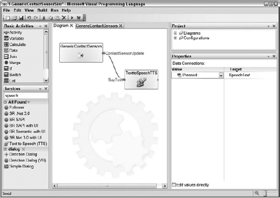
GenericContactSensorsactivity onto the diagram and connect itsContactSensorUpdatenotification to theSayTextinput of aTexttoSpeechTTSactivity. In the DataConnections dialog, connect the Pressed Value to theSpeechTextinput as shown in Figure 11-3.Press F5 to run the diagram. VPL is unable to start the service associated with the
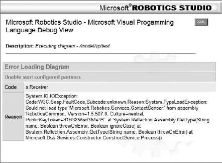
GenericContactSensorsactivity because it refers to a generic contract that has not been implemented. The error shown in Figure 11-4 is displayed in the browser.To make this work properly, you must tell VPL the service to run that implements the
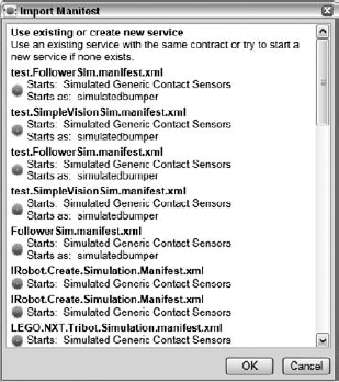
GenericContactSensorcontract. The simplest way to do this is to associate an existing manifest with the diagram. You will use a simulation manifest to keep things simple for now. Right-click the GenericContactSensors activity and select Set Configuration. In the configuration screen, select Use a Manifest and then click the Import Manifest button. A list of all the manifests underMicrosoft Robotics Studio (1.5), which contains a service that implements the GenericContactSensors contract, is shown in Figure 11-5.Select the
LEGO.NXT.Tribot.Simulation.manifest.xmlmanifest and click OK. VPL now copies this manifest into the VPL project folder along with any associated configuration files. It associates theGenericContactSensorsactivity with the SimulatedGenericContactSensors service started in the manifest.Now press F5 and the results are quite different, as shown in Figure 11-6.
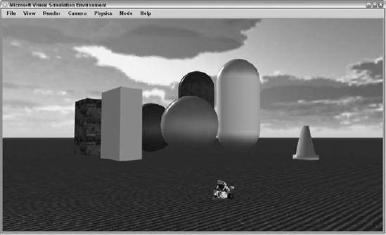
This manifest starts a number of services, including SimulationEngine. The configuration file for the SimulationEngine service contains a definition for the scene shown in Figure 11-6. Now you just need to find a way to press the simulated LEGO touch sensor to test the diagram. The easiest way to do this is to drive the LEGO Tribot into one of the obstacles in the scene, but you don't have any way to drive it because the manifest didn't start the SimpleDashboard service.
You could easily start the SimpleDashboard service at this point by opening a browser window, typing http://localhost:50000 in the address window, selecting ControlPanel and then starting the SimpleDashboard service. However, it is much nicer to configure the diagram so that the SimpleDashboard service is always launched when this diagram is executed. This is as simple as dragging the SimpleDashboard activity from the Services toolbox onto the diagram. This adds the SimpleDashboard service as a partner to the main diagram, which causes it to start when the diagram is executed.
You can load the completed diagram from 1-GenericContactSensorSim in the chapter11 directory:
Run the diagram by pressing F5.
When the SimpleDashboard window appears, type localhost in the Machine: textbox and then double-click the (LEGONXTMotorBase) service in the Service Directory list and verify that the Motor is on in the Differential Drive group box.
Press the Drive button and then drag the directional control to drive the LEGO NXT around the scene. The touch sensor is on the front of the Tribot, so try crashing it into one of the obstacles in the scene. You should hear the TexttoSpeechTTS service announce the state of the touch sensor each time it changes.
Congratulations! You have successfully used VPL to read a sensor from a simulated robot. Next you will see how easy it is to modify the diagram to use a real robot.
This example requires a LEGO NXT robot. If you don't have one, you may be able to use a different manifest that supports another robot. Even if you don't have the hardware, it is a good idea to follow along with the example to learn how you can switch a VPL diagram from working with a simulated robot to a real one.
To modify the diagram, follow these steps:
Expand the Configurations heading in the Project toolbox.
Delete the manifest that is listed there by right-clicking on it and selecting Delete.
Right-click the
GenericContactSensoractivity and select Set Configuration.In the Set Configuration screen, select Use a Manifest and click the Import Manifest button.
Select the
LEGO.NXT.Tribot.Manifest.xmlmanifest. This is similar to the simulated Tribot manifest but intended for the real LEGO hardware. Actually, at this point, you can select any manifest that is listed that works with the hardware you have.
Note
You can load a diagram that has these changes from the 2-GenericContactSensorNXT project in the chapter11 directory.
Make sure that you have set up your hardware according to the instructions in the MRDS documentation under the "Setting Up Your Hardware" topic of the Robotics Tutorials section. Press F5 to run the diagram. This time, instead of seeing the simulation environment, you should be presented with a web page that enables you to configure your LEGO NXT connection. After you have done so and clicked Connect at the bottom, the web page should indicate that the LEGO is connected. Press the touch sensor on the Tribot and you should hear the TexttoSpeechTTS service say the state of the touch sensor.
Notice that all you needed to change was the manifest associated with the diagram. In many cases, it is possible to define an algorithm using a VPL diagram that can run equally well in simulation and on a real robot simply by changing the manifest associated with the diagram.
You may have noticed that there is a GenericDifferentialDrive service in the Services toolbox. This is the generic contract to control two motors together to implement a differential drive. This activity can be used to control the motion of a differential drive robot. Consider the diagram shown in Figure 11-7, which you can find in the 3-DriveInCirclesSim project in the chapter11 directory.
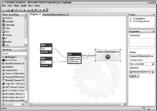
A differential drive allows a different power or speed to be specified for both the left and right drive motors. In this very simple example, the right wheel is given a drive speed of 0.5, and the left wheel drives at 0.3. Because the right wheel moves faster, the robot turns to the left at a constant rate and therefore travels in a circle, as shown in the overlay image in Figure 11-8.
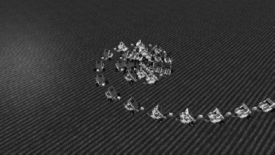
You can also specify a nice spiral with a Tribot, as shown in the 4-Spiral project in Figure 11-9.
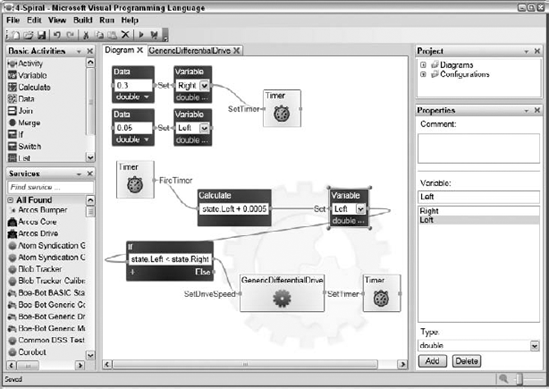
This is the first time the Timer activity has been used. A timer interval in milliseconds is passed to the SetTimer input, and after that length of time the FireTimer notification sends a message. The Right and Left variables start out at 0.3 and 0.05, respectively, which causes the Tribot to start in a tight turn. The radius of the turn is gradually increased as 0.0005 is added to the Left speed 10 times per second.
The manifest used for this example is the Lego.NXT.Tribot.Simulation.Manifest.xml manifest. Because a copy is made of the manifest and its associated configuration files when it is imported, the main camera Location and LookAt values were changed in the VPL project to change the initial viewpoint of the camera by editing the XML configuration file: lego.nxt.tribot.simulationenginestate (LEGO.NXT.Tribot.Simulation.Manifest).xml. The drive path is shown in Figure 11-10.
It is possible to control the movement of a robot more precisely by using the DriveDistance and RotateDegrees inputs of the differential drive, as illustrated in the 5-DriveDistance diagram shown in Figure 11-11.
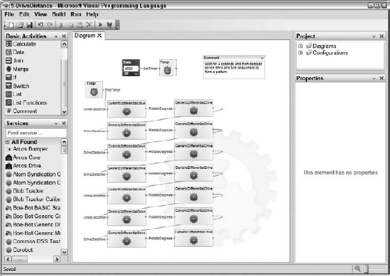
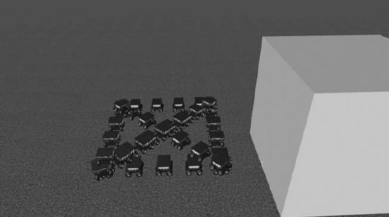
In this diagram, you use the DriveDistance and RotateDegrees inputs of the GenericDifferentialDrive to move forward a precise distance at a specified speed and then to turn a precise number of degrees at a specified speed. The Corobot manifest developed in Chapter 6 has been used for the configuration. The GenericDifferentialDrive does not send an output message until the requested motion has been completed, so the output of one motion can be fed directly to the input of another motion. The DriveDistance and RotateDegrees inputs can be used to drive a robot in a search pattern or to navigate to a specific location, as shown in Figure 11-12.
Any real robot control algorithm needs to be able to read values from multiple sensors and then control actuators such as drive motors or joint servos to move the robot. The next two examples show how this can be done together.
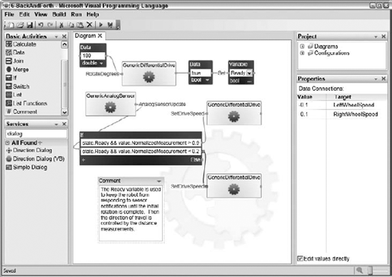
The diagram in the 6-BackAndForth project shows how to use a sensor reading to control the differential drive. You use the Corobot manifest again because it has an IR distance sensor mounted on its front and back. The IR distance sensor implements the GenericAnalogSensor contract so that is the activity used in the diagram.
The first thing the diagram does is rotate the robot by 180 degrees so that its front is facing the large box. The Ready variable is used to discard the sensor notifications until this move has been completed. After the Ready variable is set to true, the notifications from the distance sensor are used to set the motor speed. The Normalized distance value is used, which varies between 0 and 1. If the distance is larger than 0.9, then the robot is driven forward to get closer to the obstacle. If it is less than 0.2, then the motors are reversed to back away from the obstacle. The robot approaches the obstacle and then reverses before hitting it, backs away to a sufficient distance, and then approaches again. The diagram is shown in Figure 11-13.
This diagram uses two generic contract activities, and both of them must be properly configured or VPL will report an error as it is initializing.
It can be difficult to debug diagrams that have a high frequency of notifications. The debugger tends to be unresponsive due to the notification processing that is going on. In this case, it is sometimes easier to debug a diagram by inserting SimpleDialog activities at strategic points to print the values on the wire or the values of state variables. It's just like inserting printfs in the old days.
The Laser Range Finder sensor presents more of a challenge than the GenericAnalogSensor because it returns so much data. It casts 360 rays and reports the distance to intersection of each of them. It is up to the VPL diagram to interpret all of that data and determine the distance to an important object.
The 7-LaserRangeFinder project in the chapter11 directory shows one way to do this. The top-level diagram is shown in Figure 11-14; the implementation of the Evaluate action in the EvaluateRanges activity is shown in Figure 11-15.
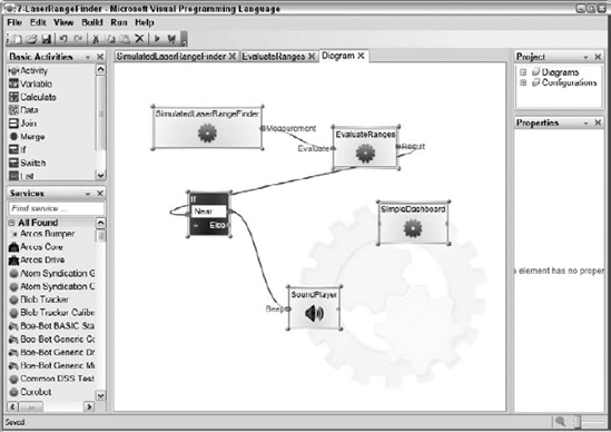
The SimulatedRangeFinder activity is configured to use the MobileRobots.P3DX.Simulation.Manifest.xml manifest. At periodic intervals, this activity sends a Measurement notification, which consists of 360 distance measurements in a list of integers along with some other data. In the main diagram shown in Figure 11-14, the data is passed to the EvaluateRanges activity along with a distance threshold. This activity then sends a response message containing a Boolean called Near, which is true if any of the distance measurements are less than the threshold. When the value is true, the SoundPlayer activity sounds a single beep. When you drive the robot so that an obstacle is nearer to the robot than the threshold distance, the diagram beeps. You can try this by running the diagram and maneuvering the robot close to one of the obstacles in the scene When you turn the robot so that the laser no longer intersects any obstacles, the beeping stops.
Let's take a closer look at how the laser range finder data is processed in the EvaluateRanges activity. The implementation of this activity is shown in Figure 11-15.
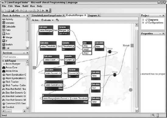
Three values are extracted from the input message and stored in state variables. The list of integers is stored in the Ranges variable, the Threshold value is stored in the Threshold variable, and the count of data values −1 is stored in the Current variable. This variable is used to count backwards through the list of data.
When all of the state variables have been initialized, the diagram enters a loop in which it steps down from the value of the Current variable to 0. If any of the ranges are less than the Threshold value, the loop takes an early exit and passes true to the output. If all of the ranges are traversed without a single one falling below the threshold, then a value of false is passed to the output.
Sometimes it is possible to implement a diagram without using any state variables at all. For example, the diagram in Figure 11-15 can be simplified by removing the Threshold, Current, and Ranges variables. Instead of being stored in variables, these values are passed around on the wires between the activities. Optimization of this diagram is left as an exercise for you.
All of the examples you have seen in this chapter so far have dealt with only a single robot or a single sensor. It has been fairly easy to configure each activity because there has been only one service to choose from in each manifest that implements the port represented by the activity. It is fairly common to have multiple sensors on a single robot that each have an associated service of the same type. In addition, it is desirable to be able to control multiple robots at the same time with a single diagram.
When there are multiple services of the same type in a manifest, you must give each service in the manifest a unique name, and then you must assign each activity to the appropriate service in the manifest.
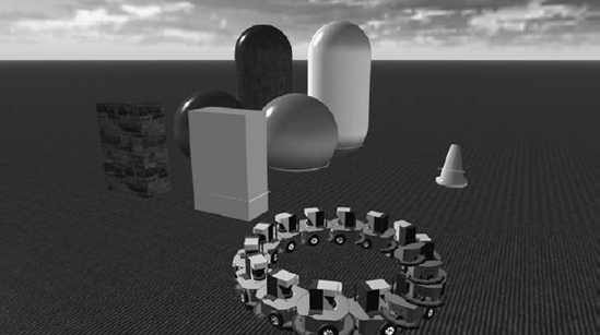
Consider the 8-TwoRobots project in the chapter11 directory. This is a very simple diagram consisting of two different GenericDifferentialDrive activities and the data to initialize the motors to unique values. The diagram is shown in Figure 11-16.
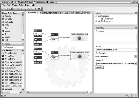
Notice that the two GenericDifferentialDrive activities have different names. This is because when the second one was dragged from the Services toolbox, VPL asked whether to create a new activity or make it refer to the existing GenericDifferentialDrive activity. A new activity was created and so it has a different name. Each of these GenericDifferentialDrive activities must be configured.
The manifest for this project was created by running the iRobot.Create.Simulation.Manifest.xml manifest and then using the Simulation Editor to duplicate the iRobot Create entity and give it a unique name. Refer to Chapter 5 for more examples of the Simulation Editor.
The manifest that runs the services assigns a different name to each of the SimulatedDifferentialDrive services, as is shown in the excerpt below. (The contracts should appear on a single line. They are shown on two lines here due to formatting constraints).
<ServiceRecordType>
      <dssp:Contract>
http://schemas.microsoft.com/robotics/simulation/services/2006/05/simulateddifferentialdrive.html
      </dssp:Contract>
      <dssp:PartnerList>
        <dssp:Partner>
          <dssp:Service>http://localhost/IRobotCreateMotorBase</dssp:Service>
          <dssp:PartnerList />
          <dssp:Name>simulation:Entity</dssp:Name>
        </dssp:Partner>
      </dssp:PartnerList>
      <Name>this:simulateddifferentialdrive</Name>
    </ServiceRecordType>
    <ServiceRecordType>
     <dssp:Contract>
http://schemas.microsoft.com/robotics/simulation/services/2006/05/simulateddifferentialdrive.html
      </dssp:Contract>
      <dssp:PartnerList>
        <dssp:Partner>
          <dssp:Service>http://localhost/IRobotCreateMotorBase0</dssp:Service>
          <dssp:PartnerList />
          <dssp:Name>simulation:Entity</dssp:Name>
        </dssp:Partner>
      </dssp:PartnerList>
      <Name>this:simulateddifferentialdrive0</Name>
    </ServiceRecordType>
The first ServiceRecord runs the SimulatedDifferentialDrive service and associates it with the IRobotCreateMotorBase entity. This service is given the name this:simulateddifferentialdrive. The second ServiceRecord runs the SimulatedDifferentialDrive service and associates it with the IRobotCreateMotorBase0 entity. This service is given the name this:simulateddifferentialdrive0.
Now, back in VPL, right-click the GenericDifferentialDrive activity and select Set Configuration. Select Use a Manifest and select the TwoCreates manifest. In the Manifest drop-down menu in the Properties toolbox, two entries appear that correspond to the names of the differentialdrive services in the manifest. Associate the simulateddifferentialdrive service with this activity. Configure the GenericDifferentialDrive0 activity in the same way, but select the simulateddifferentialdrive0 service with this activity.
Press F5 to run the diagram. Unfortunately, a bug in the 1.5 release of MRDS prevents the VPL model interpreter from running the diagram correctly; only one of the robots moves. Fortunately, you have another way to execute the diagram: compile it. A compiled version of the diagram has already been provided in the chapter11CompiledTwoRobots directory. You can also compile the diagram to another directory of your choosing. Now click Run

Use this same strategy anytime you must deal with two services of exactly the same type in a single manifest. Make sure that the services are uniquely named and then verify that each activity is paired with the proper service.
In this chapter, you've seen several simple examples of VPL diagrams that read sensor data from simulated and actual robots. In addition, you've seen several different ways to control a differential drive. The last example showed how to control multiple robots or multiple sensors of the same type from a single diagram.
The next chapter provides several more examples of VPL diagrams.