
What does a graveyard have in common with animated characters? The answer is bones. Bones are used as an underlying structure attached to a character that is to be animated. By using a bones structure, you can produce complex character motions by simply animating the bones and not having to move all the vertices associated with a high-resolution character.
Although Max includes a prebuilt skeleton with its Biped system, at times you may want to build a custom bones system because not all characters stand on two feet. Have you ever seen a sci-fi movie in which the alien was less than human-like? If your character can't be created by modifying a biped, then you need to use the traditional manual methods of rigging.
This chapter focuses on the process of manually rigging a character, which, depending on the complexity of your character, could end up being even easier than working with bipeds. It also gives you a clear idea of concepts of rigging.
A rigged character starts with a linked hierarchy. A linked hierarchy attaches, or links, one object to another and makes it possible to transform the attached object by moving the one to which it is linked. The arm is a classic example of a linked hierarchy: When the shoulder rotates, so do the elbow, wrist, and fingers. Establishing linked hierarchies can make moving, positioning, and animating many objects easy.
A bones system is a unique case of a linked hierarchy that has a specific structure. You can create a structure of bones from an existing hierarchy, or you can create a bones system and attach objects to it. A key advantage of a bones system is that you can use IK (inverse kinematics) Solvers to manipulate and animate the structure. These IK Solvers enable the parents to rotate when the children are moved. In this way, the IK Solver maintains the chain integrity. Another advantage of a bones structure is that you can constrain the motion of bones so the motion is forced to be realistic, just like a real character.
Note
IK Solvers are covered in Chapter 41, "Working with Inverse Kinematics."
After the bone structure is created, it needs to be edited to fit the skin mesh that it will control. You also need to define the limits of each bone and joint. This helps prevent the skeleton from moving in unrealistic ways. Applying IK systems is another way to control the motion of the bones and joints. This process of creating a skeleton structure and defining its limits is called rigging.
After you've edited a system of bones, you can cover the bones with objects that have the Skin modifier applied. This modifier lets the covering object move and bend with the bones structure underneath. The process of attaching a model to a bones system is called skinning.
Note
The Skin modifier is covered, along with other aspects of skinning a character, in Chapter 43, "Skinning Characters."
After a character is rigged and skinned, the character is ready to be animated.
In some instances, establishing a hierarchy of objects before linking objects is easier. By building the hierarchy first, you can be sure of the links between objects. One way to build this hierarchy is to use a bones system. A bones system consists of many bone objects that are linked together. These bone objects are normally not rendered, but you can set them to be renderable, like splines. You can also assign an IK Solver to the bones system for controlling their motion.
To create a bones system, select Create
These bones are actually linked joints. Moving one bone pulls its neighbors in the chain along with it. Bones can also be rotated, scaled, and stretched. Scaling a bones system affects the distance between the bones.
Warning
Bones should never be scaled without the XForm modifier applied or all animation keys will behave erratically.
To branch the hierarchy of bones, simply click the bone where you want the branch to start while still in bone creation mode. A new branching bone is created automatically. Click the Bones button again to create a new bone. Then continue to click to add new bones to the branch.
Figure 40.1 shows the rollouts that are available for creating bones.
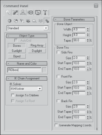
In the IK Chain Assignment rollout (found in the Modify panel when a bone is selected), you can select from four IK Solvers: History Dependent, IKHISolver, IKLimb, and SplineIK Solver. You can assign each of these solver types to children and to the root bone using the available options. You need to select both the Assign to Children and the Assign to Root options to assign the IK Controller to all bones in the system. If the Assign to Children option is deselected, then the Assign to Root option is disabled.
Note
Chapter 41, "Working with Inverse Kinematics," presents details on each of these IK Solvers.
The Bone Parameters rollout (also in the Modify panel) includes parameters for setting the size of each individual bone, including its Width and Height. You can also set the percentage of Taper applied to the bone.
Tip
Because bones are simple geometry objects, you can apply an Edit Poly modifier to it and edit the bone shape to be whatever you'd like. Custom bone geometry doesn't always work with the Bone Tools.
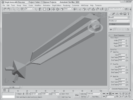
Fins can be displayed on the front, back, and/or sides of each bone. For each fin, you can specify its size and start and end taper values. Including fins on your bones makes correctly positioning and rotating the bone objects easier. Figure 40.2 shows a simple bones system containing two bones. The first bone has fins.
At the bottom of the Bone Parameters rollout is an option to Generate Mapping Coordinates. Bones are renderable objects, so this option lets you apply texture maps to them.
To practice creating a bones system, you'll take a trip to the Deep South to gator country. The main movement for this gator is going to be in its tail so you need the most bones there. The front legs are smaller and can be controlled with only two simple bones. You also won't worry about fingers.
To create a bones system for an alligator, follow these steps:
Open the Alligator bones.max file from the Chap 40 directory on the DVD.
This file includes an alligator model created by Viewpoint Datalabs.
Select Create

In the Top viewport, click once at the pelvis and then again at the mid-abdomen, the base of the neck, and the end of the nose. Then right-click to end the bones chain.
While still in Bones mode, click below the pelvis and create an additional five bones to define the tail. Then right-click to end the chain. Select the first bone in the tail chain and link it to the first joint with the Select and Link tool that moves from the pelvis to the nose, which is the root joint.
Tip
If you can't see the bones to make the link, then hide the body so the bones are clearly visible.
Click on the Bones button in the Create panel and select the bone just in front of the legs in the Top viewport (the cursor changes to a crosshair when it is over a bone) and drag to the top to form the left shoulder, left upper-arm and left lower-arm bones. Right-click to end the chain. Repeat to create bones for the left leg.
Select the Animation
Click the Select Objects button on the main toolbar to exit Bones mode, and select and name each bone object so it can be easily identified later.
Tip
The Schematic View window is a good interface for quickly labeling bones.
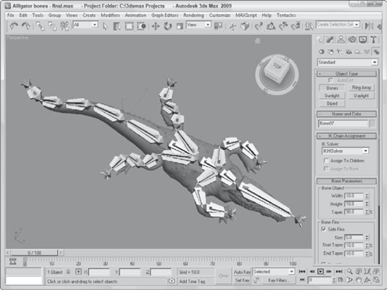
Figure 40.3 shows the completed bones system for the alligator.
After you've created a bones system, you can use the Bone Tools to edit and work with the bones system. You access these tools from a panel that is opened using the Animation
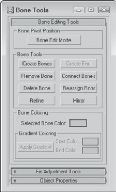
You can use the transform buttons on the main toolbar to move, rotate, and scale a bone along with all its children, but if you want to transform the parent without affecting any of the children, you need to open the Bone Tools panel using the Animation
Clicking the Remove Bone button removes the selected bone and reconnects the bone chain by stretching the child bone. If you hold down the Shift key while removing a bone, the parent is stretched. Clicking the Delete Bone button deletes the selected bone and adds an End bone to the last child.
Warning
Using the Delete key to delete a bone does not add an End bone, and the bone chain does not work correctly with an IK Solver.
If a bone exists that isn't connected to another bone, you can add an End bone to the bone using the Create End button. The bone chain must end with an End bone in order to be used by an IK Solver.
The Connect Bones button lets you connect the selected bone with another bone. After clicking this button, you can drag a line from the selected bone to another bone to connect the two bones.
Use the Reassign Root button to reverse the chain and move the End bone from the parent to the last child.
As you start to work with a bones system that you've created, you may discover that the one long bone for the backbone of your monster is too long to allow the monster to move like you want. If this happens, you can refine individual bones using the Refine button. This button appears at the bottom of the Bone Tools section of the Bone Editing Tools rollout.
Clicking the Refine button enables you to select bones in the viewport. Every bone that you select is divided into two bones at the location where you click. Click on the Refine button again to exit Refine mode.
The Mirror button lets you create a mirror copy of the selected bones. This button makes the Bone Mirror dialog box appear, where you can select the Mirror Axis and the Bone Axis to Flip. You also can specify an Offset value. In the previous example, you created arms and legs manually, but you could have created one of them and used the Mirror button to create its opposite.
Bones, like any other objects, are assigned a default object color and materials can be applied from the Material Editor. For each separate bone, its object color can be changed in the Modify panel or in the Bone Tools panel.
You can also apply a gradient to a bone chain using the Bone Tools palette. This option is available only if two or more bones are selected. The Start Color is applied to the chain's head and the End Color is applied to the last selected child. The colors are applied or updated when the Apply Gradient button is clicked. Figure 40.5 shows a long spiral bone chain with a white-to-black gradient applied.

The Fin Adjustment Tools rollout includes the same parameters as those found in the Bone Parameters rollout. You can specify the dimensions and taper of a bone and its fins. But you can also specify that the parameters are applied using Absolute or Relative values. Relative values are based on the parameters of the bone that is above the current bone in the chain.
This rollout also includes Copy and Paste buttons that you can use to copy the bone parameters from one bone to another.
You can make any object act like a bone. To make an object into a bone, you need to open the Object Properties rollout in the Bone Tools panel. The Object Properties rollout includes a setting for Bone On. If enabled, the object acts like a bone. When the Bone On/Off option is enabled, the remaining Bone controls become available. The Auto-Align option causes the pivot points of adjacent bones to be aligned automatically. The Freeze Length option causes a bone to keep its length as the bones system is moved. If the Freeze Length is disabled, you can specify a Stretch type. None prevents any stretching from occurring, and Scale changes the size along one axis, but Squash causes the bone to get wider as its length is decreased and thinner as it is elongated. You can also select to stretch an axis and choose whether to Flip the axis.
You can use the Realign button to realign a bone; click the Reset Stretch button to normalize the stretch value to its current value.
The benefits of a bones system become more apparent in the next chapter when I cover inverse kinematics. In this chapter, you learned how to create and work with bones systems and the Bone Tools. This chapter covered the following topics:
Creating bones systems
Setting bone parameters and the IK Solver
Using the Bone Tools
Making objects into bones systems
If you're feeling pretty good about the skeleton you've created, the next part of rigging is applying the IK Solver that is used to tell the bones how to move relative to one another. This also gives you the chance to constrain the bone's movement. The second part of rigging characters is covered in the next chapter along with Inverse Kinematics.