
Kinematics is a branch of mechanics that deals with the motions of a system of objects, so inverse kinematics would be its evil twin brother that deals with the non-motion of a system of objects. Well, not exactly.
In Max, a system of objects is a bunch of objects that are linked together. After a system is built and the parameters of the links are defined, the motions of all the pieces below the parent object can be determined as the parent moves using kinematics formulas.
Inverse kinematics (IK) is similar, except that it determines all the motions of objects in a system when the last object in the hierarchy chain is moved. The position of the last object, such as a finger or a foot, is typically the one you're concerned with. Using IK, you can then use these solutions to animate the system of objects by moving the last object in the system.
Before you can understand IK, you need to realize that another type of kinematics exists—forward kinematics. Kinematics solutions work only on a kinematics chain, which you can create by linking children objects to their parents.
Note
Chapter 9, "Grouping, Linking, and Parenting Objects," covers linking objects and creating kinematics chains.
Forward kinematics causes objects at the bottom of a linked structure to move along with their parents. For example, consider the linked structure of an arm, where the upper arm is connected to a forearm, which is connected to a hand, and finally to some fingers. Using forward kinematics, the lower arm, hand, and fingers all move when the upper arm is moved.
Having the linked children move with their parent is what you would expect and want, but suppose the actual object that you wanted to place is the hand. IK enables child objects to control their parent objects. So, using IK, you can drag the hand to the exact position you want, and all other parts in the system follow.
Forward kinematics in Max involves simply transforming linked hierarchies. Any time you move, rotate, or scale a linked hierarchy, the children move with the parent, but the child object can also be transformed independent of its parent.
Before you can animate an IK system, you need to build and link the system, define joints by positioning pivot points, and define any joint constraints you want.
The first step in creating an IK system is to create and link several objects together. You can create links using the Link button on the main toolbar.
With the linked system created, position the child object's pivot point at the center of the joint between it and its parent. For example, the joint between an upper and lower arm would be at the elbow, so this is where the pivot point for the lower arm should be located.
Note
Chapter 9, "Grouping, Linking, and Parenting Objects," covers creating linked systems, and Chapter 7, "Transforming Objects, Pivoting, Aligning, and Snapping," covers moving pivot points.
After you create the linked system and correctly position your pivot points, open the Hierarchy panel and click the IK button. Several rollouts open that let you control the IK system, including the Object Parameters rollout shown in Figure 41.1.
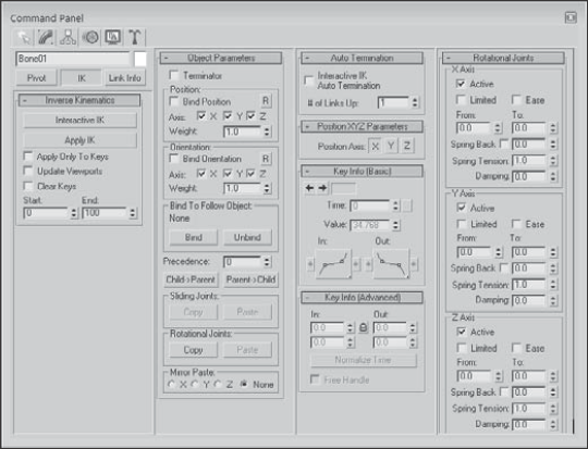
Because child objects in an IK system can cause their parents to move, moving a child could cause unwanted movements all the way up the system to the root object. For example, pulling on the little finger of a human model could actually move the head. To prevent this, you can select an object in the system to be a terminator.
A terminator is the last object in the IK system that is affected by the child's movement. Making the upper arm a terminator would prevent the finger's movement from affecting any objects above the arm.
To set a terminator, select an object and then enable the Terminator option in the Object Parameters rollout.
For Interactive IK mode, you can also enable the Auto Termination option included in the Auto Termination rollout. The Number (#) of Links Up value sets the terminator a specified number of links above the current selection.
The next step is to define the joint constraints, which you specify in the Sliding Joints and Rotational Joints rollouts. By default, each joint has six degrees of freedom, meaning that the two objects that make up the joint can each move or rotate along the X-, Y-, or Z-axes. The axis settings for all other sliding and rotational joints are identical. Defining joint constraints enables you to constrain these motions in order to prevent unnatural motions, such as an elbow bending backward. To constrain an axis, select the object that includes the pivot point for the joint, locate in the appropriate rollout the section for the axis that you want to restrict, and deselect the Active option. If an axis's Active option is deselected, the axis is constrained. You can also limit the motion of joints by selecting the Limited option.
When the Limited option is selected, the object can move only within the bounds set by the From and To values. The Ease option causes the motion of the object to slow as it approaches either limit. The Spring Back option lets you set a rest position for the object; the object returns to this position when pulled away. The Spring Tension sets the amount of force that the object uses to resist being moved from its rest position. The Damping value sets the friction in the joint, which is the value with which the object resists any motion.
Note
As you enter values in the From and To fields, the object moves to that value to show visually the location specified. You can also hold down the mouse on the From and To values to cause the object to move temporally to its limits. These settings are based on the current Reference Coordinate system.
Defining joint constraints can be lots of work—work that you wouldn't want to have to duplicate if you didn't have to. The Copy and Paste buttons in the Object Parameters rollout enable you to copy Sliding Joints or Rotational Joints constraints from one IK joint to another.
To use these buttons, select an IK system and click the Copy button; then select each of the joints to be constrained in a similar manner, and click the Paste button. You also have an option to mirror the joints about an axis. It is useful for duplicating an IK system for opposite arms or legs of a human or animal model.
When using applied IK, you need to bind an object in the IK system to a follow object. The IK joint that is bound to the follow object then follows the follow object around the scene. The bind controls are located in the Hierarchy panel under the Object Parameters rollout. To bind an object to a follow object, click the Bind button in the Object Parameters rollout and select the follow object.
In addition to binding to a follow object, IK joints can also be bound to the world for each axis by position and orientation. This causes the object to be locked in its current position so it won't move or rotate along the axis that is selected. You can also assign a Weight value. When the IK computations determine that two objects need to move in opposite directions, the solution favors the object with the largest Weight value.
The Unbind button eliminates the binding.
When Max computes an IK solution, the order in which the joints are solved determines the end result. The Precedence value (located in the Object Parameters rollout) lets you set the order in which joints are solved. To set the precedence for an object, select the object and enter a value in the Precedence value setting. Max computes the object with a higher precedence value first.
The default joint precedence for all objects is 0. This assumes that the objects farthest down the linkage move the most. The Object Parameters rollout also includes two default precedence settings. The Child to Parent button sets the precedence value for the root object to 0 and increments the precedence of each level under the root by 10. The Parent to Child button sets the opposite precedence, with the root object having a value of 0 and the precedence value of each successive object decreasing by 10.
As an example of a kinematics system, you'll start with a backhoe, which is a simple linkage system with tracks that can move forward, a chair housing that can rotate independently, and an arm and bucket that can rotate about a pivot. When you're finished with this tutorial, you can take the backhoe out and dig a hole for a swimming pool. I think you deserve it.
To create an inverse kinematics system for a backhoe, follow these steps:
Open the Backhoe.max file from the Chap 41 directory on the DVD.
Open the Schematic View window with the Graph Editors

Note
You can learn more about the Schematic View window in Chapter 24, "Working with the Schematic View."
Next, you need to define the pivots for the objects that can rotate. Select the housing, and notice that its pivot is already located in the center of the base cylinder where it should be. Then select the arm, open the Hierarchy panel, and click the Pivot button. Click the Affect Pivot Only button, and move the pivot to the center of the cylinder that connects it to the housing. Then do the same for the bucket. Click the Affect Pivot Only button again to exit pivot-editing mode.
The next step is to define the joint constraints for the system. Open the Hierarchy panel, and click the IK button. In the Object Parameters rollout, select the base cylinder and enable the Terminator, Bind Position, and Bind Orientation options; doing so prevents the base cylinder from moving anywhere. In the Rotational Joint rollout, deactivate all the axes.
Select the housing object, and enable the Bind Position axes and the X and Y Orientation axes. Then disable the X and Y Rotation axes. Select the arm object and enable all the Bind Position axes and the X and Z Orientation axes. Then disable the X and Z Rotational axes. Then click the Copy button for the Rotational joint type in the Object Parameters rollout, select the bucket object, and click the Paste button. This copies the joint constraints from the arm object to the bucket object.
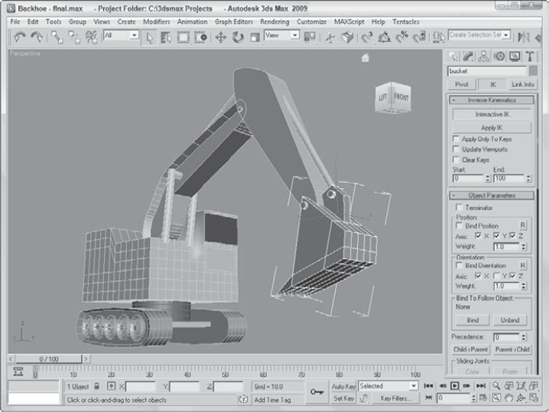
To test the system, select the Interactive IK button in the Inverse Kinematics rollout and select and move the bucket.
As the bucket is moved, the arm rotates and the housing spins about its axis just as you'd expect.

Figure 41.3 shows the bucket moving. With the Interactive IK mode disabled, any object can be moved and/or rotated, and only the links are enforced.
After you create a linked hierarchy chain, you need to apply an IK method to the chain before you can animate it. Max includes several different methods for animating using IK. The traditional methods of Interactive and Applied IK are now joined with IK solvers. The Interactive and Applied IK methods are applied using the Hierarchy panel; the IK solvers can be applied to a bones system, or you can use the Animation
An IK solver is a specialized controller that computes an IK solution. This solution is used to automatically set all the required keys needed for the animation. Max offers four different IK solvers: History Dependent (HD) IK, History Independent (HI) IK, IK Limb, and SplineIK solvers.
Interactive IK is the method that lets you position a linked hierarchy of objects at different frames. Max then interpolates all the keyframes between the various keys. This method isn't as precise, but it uses a minimum number of keys and is useful for an animation sequence involving many frames. Interactive IK interpolates positions between the two different keys, whereas Applied IK computes positions for every key. Because the motions are simple interpolations between two keys, the result may not be accurate, but the motion is smooth.
After your IK system is established, animating using the Interactive IK method is simple. First, you need to enable the Auto Key button and select the Interactive IK button in the IK rollout of the Hierarchy panel. Enabling this button places you in Interactive IK mode, causing the system to move together as a hierarchy. Then reposition the system in a different frame; Max automatically interpolates between the two positions and creates the animation keys. To exit Interactive IK mode, simply click the Interactive IK button again.
The IK rollout includes several options. The Apply Only to Keys option forces Max to solve IK positions for only those frames that currently have keys. The Update Viewports option shows the animation solutions in the viewports as it progresses, and the Clear Keys option removes any existing keys as the solution is calculated. The Start and End values mark the frames to include in the solution.
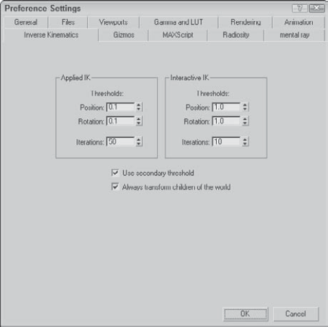
The required accuracy of the IK solution can be set using the Inverse Kinematics panel in the Preference Settings dialog box, shown in Figure 41.4. You can open this dialog box by choosing Customize
You can also set an Iterations limit for both methods. The Iterations value is the maximum number of times the calculations are performed. This value limits the time that Max spends looking for a valid solution. The Iterations settings control the speed and accuracy of each IK solution.
Note
If the Iterations value is reached without a valid solution, Max uses the last calculated iteration.
The Use Secondary Threshold option provides a backup method for determining whether Max should continue to look for a valid solution. This method should be used if you want Max to bail out of a particularly difficult situation rather than to continue to try to find a solution. If you are working with very small thresholds, you want to enable this option.
The Always Transform Children of the World option enables you to move the root object when it is selected by itself but constrains its movement when any of its children are moved.
Machines are good examples of a kinematics system. In this example, you animate a simple gear-and-propeller system using the Applied IK method.
To animate an inverse kinematics system with a propeller, follow these steps:
Open the Gear and prop.max file from the Chap 41 directory on the DVD.
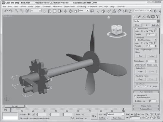
This file includes a simple handle and prop system.
The first task is to link the model. Click the Select and Link button on the main toolbar. Then drag from each child object to its parent. Connect the propeller to the shaft, the shaft to the gear, and the gear to the handle.
Open the Hierarchy panel, and click the IK button. Next constrain the motions of the parts by selecting the handle object. All Sliding Joints can be deactivated, and only the Z Axis Rotational Joint needs to be activated. To do this, make sure that a check mark is next to the Active option. When this is set for the handle object, click the Copy button for both joint types, select the gear object, and click Paste to copy these constraints. Then select the shaft object, click both Paste buttons again, and repeat this process for the propeller.
Finally, enable the Auto Key button (or press the N key), drag the Time Slider to frame 100 (or press the End key), and click the Interactive IK button in the Inverse Kinematics rollout of the Hierarchy panel. Then select the Select and Rotate button (E), and drag in the Left viewport to rotate the handle about its Z-axis.
Figure 41.5 shows the propeller system.
Applied IK applies a solution over a range of frames, computing the keys for every frame. This task is accomplished by binding the IK system to an object that it follows. This method is more precise than the interactive IK method, but it creates lots of keys. Because keys are set for every object and every transform, this solution sets lots of keys, which increases the size and complexity of the scene. Each frame has its own set of keys, which could result in jerky, non-smooth results.
Note
Because the Applied IK method is more accurate, you want to set its Threshold values lower than those of the Interactive IK method.
To animate using the Applied IK method, you need to bind one or more parts of the system to a follow object, which can be a dummy object or an object in the scene. You do so by clicking the Bind button in the Object Parameters rollout of the Hierarchy panel and selecting an object in one of the viewports. After the system has a bound follow object, select an object in the system. Open the Hierarchy panel; in the Inverse Kinematics rollout, click the Apply IK button. Max then computes the keys for every frame between the Start and End frames specified in the rollout. Click the Apply IK button to start the computation process that sets all the animation keys for the range of frames indicated.
Tip
If you plan on using the Applied IK method, set the Threshold values in the Inverse Kinematics panel of the Preference Settings dialog box to small values in order to ensure accurate results.
The History Independent (HI) IK solver looks at each keyframe independently when making its solution. You can animate linked chains with this IK solver applied by positioning the goal object; the solver then keyframes the position of the pivot point of the last object in the chain to match the goal object.
You can apply IK solvers to any hierarchy of objects. IK solvers are applied automatically to a bones system when you create the system. You can also choose Animation
When you choose Animation
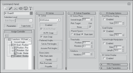
The first rollout is the IK Solver rollout, shown in Figure 41.6. Using this rollout, you can select to switch between the HI IK solver and the IK Limb solver. The Enabled button lets you disable the solver. By disabling the solver, you can use forward kinematics to move the objects. To return to the IK solution, simply click the Enabled button again. The IK for FK Pose option enables IK control even if the IK solver is disabled. This lets you manipulate the hierarchy of objects using forward kinematics while still working with the IK solution. If both the IK for FK Pose and the Enabled buttons are disabled, then the goal can move without affecting the hierarchy of objects.
If the goal ever gets moved away from the end link, clicking the IK/FK Snap button automatically moves the goal to match the end links position. Auto Snap automatically keeps the goal and the end link together. The Set as Preferred Angle button remembers the angles for the IK system. These angles can be recalled at any time using the Assume Preferred Angle button.
When you choose Animation
Tip
The best way to select an object using the Pick Start or End Joint buttons is to open the Select by Name dialog box by pressing the H key. Using this dialog box, you can select an exact object without having to miss selecting it in a complex viewport.
Warning
If you select a child as the start joint and an object above the child as the end joint, then moving the goal has no effect on the IK chain.
The IK Solver Properties rollout includes the Swivel Angle value. The swivel angle defines the plane that includes the joint objects and the line that connects the starting and ending joints. This plane is key because it defines the direction that the joint moves when bent.
The Swivel Angle value can change during an animation. Using the Pick Target button, you can also select a Target object to control the swivel angle. The Use button turns the target on and off. The Parent Space group defines whether the IK Goal's parent object or the Start Joint's parent object is used to define the plane. Having an option lets you select two different parent objects that control the swivel plane if two or more IK solvers are applied to a single IK chain.
You can also change the Swivel Angle value by using a manipulator. To view the manipulator, click the Select and Manipulate button on the main toolbar. This manipulator is a green line with a square on the end of it. Dragging this manipulator in the viewports causes the swivel angle to change.
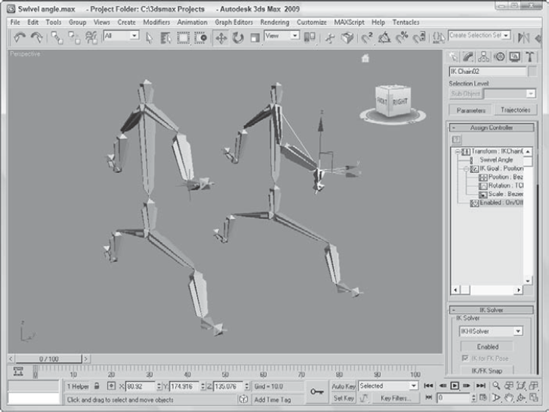
To understand the swivel angle, consider the two puppet bones systems displayed in Figure 41.7. The HI solver has been applied to the right arms of both puppets with the upper arm as the beginning joint and the hand as the end joint. The swivel angle for the left bones system is 90 degrees, and the swivel angle for the right bones system is 180. You can see the manipulators for both bones systems. The left one is pointing upward, and the right one is pointing straight out from the puppet's head. Notice that the swivel angle determines the direction the elbow joint is pointing. The left bones system's elbow is pointing up and away from the spine, and the right bones system's elbow is pointing painfully out in front of the puppet in the direction of the manipulator.
The IK Solver Properties rollout also includes Threshold values. These values determine how close the end joint and the goal must be before the solution is pronounced valid. You can set thresholds for Position and Rotation. The Iterations value sets the number of times the solution is tried.
Tip
Setting the Iterations value to a higher number produces smoother (less jerky) results, but it increases the time required to find a solution.
The IK Display Options rollouts can enable, disable, and set the size of the gizmos used when working with IK solvers. Using this rollout, you can Enable the End Effector, the Goal, the Swivel Angle Manipulator, and the IK solver (which is the line connecting the start and end joints).
The HI solver is probably the best solver to use for animating characters. This fine fellow made of bones makes a good candidate for trying out the HI solver.
To animate an alligator with the HI IK solver, follow these steps:
Open the Dancing puppet.max file from the Chap 41 directory on the DVD.
This file is the same file that was created using the bones system.
Apply the HI solver to the arm chains by selecting the left upper arm and choosing Animation
Repeat Step 2 for the right arm and both leg chains.
Click the Auto Key button, and drag the Time Slider to frame 20. Select the goal for the left leg IK chain, click the Select and Move button on the main toolbar (or press the W key), and move the left leg goal upward.
Repeat Step 4 for frames 40, 60, 80, and 100, moving the various IK chains in different directions.
Move the Time Slider to frame 50, and select all objects by choosing Edit
Click the Play Animation button (/) to see the resulting dance.
Figure 41.8 shows one frame of the dancing puppet.
The History Dependent (HD) IK solver takes into account the previous keyframes as it makes a solution. This solver makes having very smooth motion possible, but the cost of time to compute the solution is increased significantly. You can also assign this IK solver to bones systems by specifying the History Dependent solver in the IK Chain Assignment rollout or by choosing Animation
This IK solver shows up as a controller in the Motion panel when the IK chain is selected. The settings are contained in a rollout named IK Controller Parameters, which is visible in the Motion panel if you select one of the end effector gizmos. The end effector gizmo is the object that you move to control the IK chain. It is displayed as a set of crossing axes.

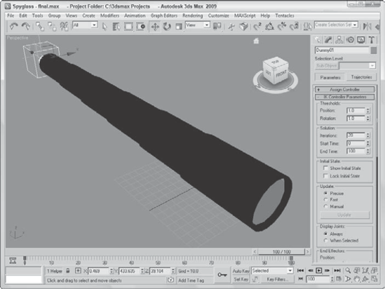
You can access the IK Controller Parameters rollout, shown in Figure 41.9, in the Motion panel. Any parameter changes affect all bones in the current structure. In the Thresholds section, the Position and Rotation values set how close the end effector must be to its destination before the solution is complete. In the Solution section, the Iterations value determines the maximum number of times the solution is attempted. These Thresholds and Iterations values are the same as those in the Preference Settings dialog box, except that they affect only the current linkage. The Start Time and End Time values set the frame range for the IK solution.

The Show Initial State option displays the initial state of the linkage and enables you to move it by dragging the end effector object. The Lock Initial State option prevents any linkage other than the end effector from moving.
The Update section enables you to set how the IK solution is updated with Precise, Fast, and Manual options. The Precise option solves for every frame, Fast solves for only the current frame, and Manual solves only when the Update button is clicked. The Display Joints options determine whether joints are Always displayed or only When Selected.
When you first create a bones system, an end effector is set to the last joint automatically. In the End Effectors section, at the bottom of the IK Controller Parameters rollout, you can set any joint to be a Positional or Rotational end effector. To make a bone an end effector, select the bone and click the Create button. If the bone already is an end effector, then the Delete button is active. You can also link the bone to another parent object outside of the linkage with the Link button. The linked object then inherits the transformations of this new parent.
Click the Delete Joint button in the Remove IK section to delete a joint. If a bone is set to be an end effector, the Position or Rotation button displays the Key Info parameters for the selected bone.
A telescoping spyglass is a good example of a kinematics system that you can use to show off the HD solver. The modeling of this example is also easy because it consists of a bunch of cylinders that gradually get smaller.
To animate a spyglass with the HD IK solver, follow these steps:
Open the Spyglass.max file from the Chap 41 directory on the DVD.
This file includes a simple spyglass made from primitive objects. The pieces of the spyglass are linked from the smallest section to the largest section. At the end of the spyglass is a dummy object linked to the last tube object.
First, you need to define the joint properties. Select the largest tube object, open the Hierarchy panel, and click the IK button. In the Object Properties rollout, select the Terminator, Bind Position, and Bind Orientation options to keep this joint from moving.
With the largest tube section selected, make the Z Axis option active in the Sliding Joints rollout, and disable all the axes in the Rotational Joints rollout. Then click the Copy button for both Sliding Joints and Rotational Joints in the Object Properties rollout.
Select each remaining tube object individually, and click the Paste buttons for both the Sliding Joints and Rotational Joints.
This enables the local Z-axis sliding motion for all tube objects.
Select the largest tube section again, and choose Animation
Select the second tube object, and for the Sliding Z Axis, select the Limited option with values from 0.0 to −80. Then click on the Copy button for the Sliding Joints in the Object Parameters rollout. Then select tubes 3 through 6 individually, and click the Paste button for the Sliding Joints to apply these same limits to the other tube objects.
Click the Auto Key button (N), drag the Time Slider to frame 100 (End), select the Select and Move button on the main toolbar (W), and drag the dummy object away from the largest tube object.
Figure 41.10 shows the end tube segment collapsing within the spyglass.
The IK Limb solver was specifically created to work with limbs. It is used on chains of three bones such as a hip, upper leg, and lower leg. Only two of the bones in the chain actually move. The goal for these three joints is located at the pivot point for the third bone. This solver is ideal for game character rigging.
The way this solver works is that it considers the first joint as being a spherical joint that can rotate along three different axes, like a hip or shoulder joint. The second joint can bend only in one direction, such as an elbow or knee joint.
The rollouts and controls for the IK Limb solver are exactly the same as those used for the HI solver covered earlier in this chapter.
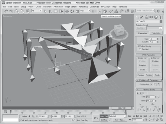
As an example of the IK Limb solver, you should probably animate a limb, so I've created a simple spider skeleton with not two limbs, but eight. I created this skeleton fairly quickly using four bones for the abdomen; then I created one limb and cloned it three times. Then I used the Bone Tools to connect the leg bones to the abdomen bones, and finally I selected and mirrored the bones on all four legs to get the opposite legs. The hardest part was naming all the bones.
To animate a spider skeleton's leg using the IK Limb solver, follow these steps:
Open the Spider skeleton.max file from the Chap 41 directory on the DVD.
Click the Select by Name button on the main toolbar (or press the H key) to open the Select Objects dialog box. Double-click the "RUpperlegBone0l" object to select the upper leg bone object.
With the upper leg bone selected, choose Animation
This bone corresponds to the foot bone, which is the end of the limb hierarchy.
With the IK Chain01 object selected, click the Auto Key button (or press the N key) and drag the Time Slider to frame 100 (End). With the Select and Move button (W), move the IK chain in the viewport.
The leg chain bends as you move the end effector.
Figure 41.11 shows the spider's leg being moved via the IK Limb solver. The IK Limb Solver provides a simple and quick way to add an effector to the end of a limb, giving you a good control for animating the spider's walk cycles.
The Limb IK solver works well for arms and legs that have a joint in their middle, but it doesn't work well for tails. Tails are unique because they require multiple bones to deform correctly. The Spline IK solver works well for tails, but it also works well for rigging tentacles, chains, and rope.
To use the Spline IK solver, you need to create a chain of bones and a spline path. By selecting the first and last bone and then selecting the spline, the bone chain moves to the spline. Each control point on the spline has a dummy object associated with it. By moving these dummy objects, you can control the position of the bones. At either end of the spline are manipulators that you can use to twist and rotate the bones.
The easiest way to use this IK solver is to select SplineIKSolver from the drop-down list in the IK Chain Assignment rollout while you're creating the bone structure. After the bone structure is complete, the Spline IK Solver dialog box appears. With this dialog box, you can select a name for the IK chain, specify the curve type, and set the number of spline knots. The curve type options include Bézier, NURBS Point, and NURBS CV. You can also select to Create Helpers and to display several different options.
Another way to use this IK solver is with an existing bone structure. To do this, you need a spline curve in the scene that matches how you want the bone chain to look. Then select the first bone where you want the solver to be applied, and choose Animation
The bone structure then assumes the shape of the spline curve. A helper object is positioned at the location of each curve vertex. These helper objects let you refine the shape of the curve.
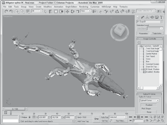
The IK Spline solver is perfect for creating long, winding objects like snakes or an alligator's tail. For this example, you'll take an existing bone structure and, using the Spline IK solver, make it match a spline.
To create a bone structure for an alligator that follows a spline using the IK Spline solver, follow these steps:
Open the Alligator spline IK.max file from the Chap 41 directory on the DVD.
This file includes an alligator model created by Viewpoint Datalabs, a simple bone chain, the Skin modifier, and a spline.
Tip
If you're having trouble seeing the bones located inside the alligator, you can enable the See Through option in the Object Properties dialog box or press the Alt+X keyboard shortcut.
With the first bone in the tail chain selected, choose Animation
A dragging line appears in the viewport extending from the first bone.
Drag and click the cursor on the last bone in the bone tail chain.
Another dragging line appears; drag and click on the spline, and the bone structure moves to match the spline's curve.
Figure 41.12 shows the bone structure for the gator's tail. You can now control the gator's tail by moving the dummy objects along the spline.
Inverse kinematics (IK) provides a unique way to control and animate hierarchical structures by transforming the child node. In this chapter, you accomplished the following:
Learned the basic concepts behind IK
Explored the difference between interactive and applied IK methods
Created and animated an IK system
Used the IK settings in the Preference Settings dialog box
Learned how to use IK solvers
Now that you've learned the process for rigging a character and using IK, we'll take a look at using Biped next and discover the benefits of using a pre-rigged skeleton.