
Max has always had a great way to create and animate characters, but in early versions of Max, it was available only as a separate plug-in known as Character Studio. Happily, Character Studio has been integrated into Max to the point that it isn't distinguishable as a separate package. In fact, some of Max's original features have overgrown Character Studio, but much of Character Studio's original, innovative features still exist and are extremely useful, including Biped.
Using Biped, you can create a fully linked and constrained human-form skeleton by simply dragging in the viewport. Biped objects can be altered in many ways while retaining their benefit. The major benefit of bipeds is that you can realistically animate them by simply positioning their footprints or setting freeform keys.
Although Max includes other features for rigging characters, if you plan on animating a character that walks on two legs and has two arms, then biped is definitely the way to go. It's an incredible timesaver.
Nobody likes crowds (except for certain types of bugs), but with the Character Studio's Crowd Animation tools, controlling crowds can be lots of fun. The fun comes when you realize that you would spend weeks animating by hand all the actions that are possible with the Crowd animation tools.
Characters included in a crowd simulation are called delegates, and these delegates can have assigned behaviors that tell them to follow a certain object or a certain path and to avoid designated objects. As you begin to simulate crowds, you'll delight in how much it is like taking the whole family shopping together, except the delegates actually do what you say.
A typical workflow for creating characters in Max involves first creating a skin mesh object. After the skin mesh is complete, you can create a biped object to drive its animation. The biped consists of a pre-rigged skeleton of bones that provide an underlying structure to the character. Animating these bones provides an easy way to give life to the character.
With a biped created, position the biped within the skin mesh and match the bone links to the relative size and position inside the skin mesh. The bones do not need to be completely within the skin mesh given you can set the biped objects to not be rendered, but the closer they are to the skin mesh, the more accurate the movements of the character are.
After the biped is sized and matched to the skin mesh, use the Skin modifier to attach the skin mesh to the biped. This automatically sets all the envelopes that govern which skin parts move with which bones. You can also use the Skin modifier settings to deform the skin at certain bone angles, such as bulging a muscle when the arm is raised.
Note
The original Character Studio package used the Physique modifier to bind the mesh skin to the biped. Although this modifier still exists and can be used, the Skin modifier includes many new features and is the preferred method for binding a mesh skin to the biped.
The next step is to animate the biped using its animation tools, which can include walk, run, and jump cycles by placing footsteps or freeform animation using keys. Along the way, you can save, load, and reuse animation sequences including motion capture files. Animated sequences can be combined and mixed together to form a smooth-flowing animation using the Motion Mixer.
Creating a hierarchical skeleton that is used to control the animation of the mesh skin that is draped over it is quite easy when you create a biped. The skeleton can be set to be invisible in the final render and exists only to make the process of animating easier. Although Max includes a robust set of tools that can be used to create a skeleton of bones, the Biped feature automates this entire process using prebuilt skeletons.
Note
For some characters, manipulating a biped is more work than building a custom skeleton. For these occasions, you can manually create a skeleton structure. Building a skeleton system by hand is covered in Chapter 40, "Understanding Rigging and Working with Bones."
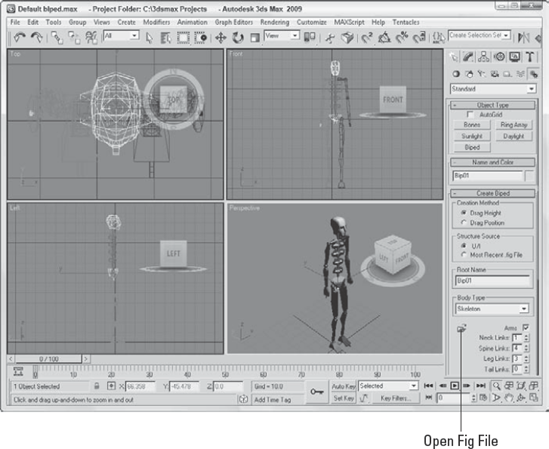
To create a biped, simply select the Create
The Create Biped rollout includes two creation methods: Drag Height and Drag Position. The Drag Height creation method lets you set the height of the biped by dragging in the viewport, and the Drag Position creation method creates a standard-sized biped and lets you position it by dragging about the viewport.
Note
To precisely position a biped on the surface of any existing object, enable the AutoGrid option at the top of the Object Type rollout.
In the Root Name field, you can name the biped. Every biped bone is given a unique name, and this root name is attached to the front of the unique bone name. For example, if you specify Gloop as the root name, then the right calf bone is given the name Gloop R Calf.
Below the Biped Name field is the Body Type drop-down list. In this list, you can select from Skeleton, Female, Male, and Classic body types. The differences among these body types relate to the size and shape of the bones. The Classic body type was used in previous versions of Character Studio and exists for backward compatibility. Figure 42.2 shows each of these body types.
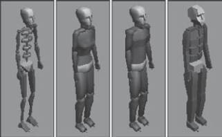
By default, all biped bones are color coded, with all bones on the right side colored green and all bones on the left side colored blue. The pelvis, which is the root bone, is colored yellow, and the head is light blue. These colors help keep the different bones straight, and the same colors are used for the footprints that define the biped's motion.
Although the standard biped resembles a human form, you can use the settings in the Create panel to radically change the biped to resemble whatever creature you've created.
Customized biped skeletons can be saved using the Save File button found in the Motion panel when Figure Mode is enabled. Biped files are saved with the .fig file extension. Saved biped files can then be recalled when a new biped is being created using the Open Fig File button in the Create Biped rollout. You can also select to create any new bipeds using the user interface settings or using the Most Recent .fig file.
Note
The Save File button saves the skeleton structure as a .fig file when Figure Mode is enabled and saves the animation sequence as a .bip file when Figure Mode is disabled.
The Create Biped rollout includes settings for toggling the arms on and off. Settings are available for controlling the number of links used to represent all the various body parts listed in Table 42.1. These same settings are available in the Structure rollout of the Motion panel, which is available when Figure Mode is enabled.
Table 42.1. Biped Parts
Body Part | Link Limits |
|---|---|
Arms | On or Off |
Neck Links | 1 to 25 |
Spine Links | 1 to 10 |
Leg Links | 3 to 4 |
Tail Links | 0 to 25 |
Ponytail1 Links | 0 to 25 |
Ponytail2 Links | 0 to 25 |
Fingers | 0 to 5 |
Finger Links | 1 to 3 |
Toes | 1 to 5 |
Toe Links | 1 to 3 |
Props | Up to 3 enabled |
Ankle Attach | 0.0 (back of foot) to 1.0 (front of foot) |
Height | unlimited |
Triangle Pelvis | On or Off |
Triangle Neck | On or Off |
Forefeet | On or Off |
Twist Links | On or Off |
Upper Arm Twist Links | 0 to 10 |
0 to 10 | |
Thigh Twist Links | 0 to 10 |
Calf Twist Links | 0 to 10 |
Horse Link Twist Links | 0 to 10 (Leg links must be set to 4 to use Horse Links) |
Ponytail links are located on the back of the head and, like the arms, will naturally hang down when the spine bones are rotated. Tail links extend as expected off the back of the pelvis bone. Enabled Props appear as tall rectangular boxes attached to the hands. Prop1 is attached to the right hand, Prop2 is attached to the left hand, and Prop3 floats on the left side of the body.
Figure 42.3 shows a biped with two ponytails, a tail, and a single prop.
Tip
Ponytail objects can be used to represent ears, horns, or a unique haircut that moves independently of the head.
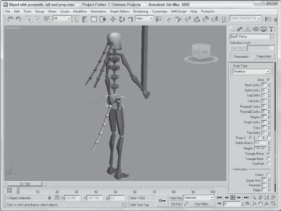
Figure 42.3. This biped includes two ponytails, a tail, and a prop object attached to its right hand.
The Triangle Pelvis option isn't initially visible when creating a biped, but if enabled, the pelvis consists of two links that extend from the spine to where the leg links are located. This helps keep the leg joints from intersecting directly under the spine. You can also select to use a Triangle Neck bone, which extends to connect to the clavicle bones, helping deform the skin better. The Forefeet option causes the biped hands to act like feet, which is helpful for creating quadruped characters.
Note
The Triangle Neck and Forefeet options are new to 3ds Max 2009.
The twist links feature allows body parts to twist during animation. The Twists option needs to be enabled before twist links can be used, and the twist links are frozen by default. For example, if you hold your arm out to the side with your palm facing forward, the ulna and radius bones that make up your forearm are actually rotated 90 degrees.
Note
The twist links feature, located at the bottom of the Structure rollouts, cannot be animated individually; it can be used only to deform the skin as the body part is animated.
If your character has some other specialized body parts that can't be covered using the typical Biped structure elements, you can use the Xtras section to add custom structures that are parented to any existing biped part, even to other Xtras. For example, if you're creating a flying monkey with a tail and wings sticking out from the monkey's shoulders, Xtras can be used to add the new wings.
Each new Xtra added to the biped can have up to 25 links, and you can select the biped object to link the Xtra part to. The Xtras controls, shown in Figure 42.4, also include buttons to automatically select and/or create a symmetrical part. New Xtras are highlighted red and yellow until an opposite is created. Then they become blue and green to match the biped's left and right sides. New Xtras can be renamed using the name field.

After a biped is created, you may look to the Modify panel to change the biped, but the Modify panel is empty. Don't be surprised: All the controls for modifying a biped are located in the Motion panel. This is because a biped deals with animation and not just with modifying structures.
In the Biped rollout of the Motion panel, you see several icons. These icons are described in Table 42.2.
Table 42.2. Biped Rollout Button
Toolbar Button | Name | Description |
|---|---|---|
Figure Mode | Enables Figure Mode, where you can edit the skeleton structure | |
Footstep Mode | Enables Footstep Mode, where you can animate the biped by placing footsteps to follow | |
Motion Flow Mode | Enables Motion Flow Mode, where you can create scripts of motions for a biped to follow | |
Mixer Mode | Enables Mixer Mode, where you can load and save Mixer files | |
Biped Playback | Plays the animated biped in the viewport in real time showing only the bones | |
Load File | Opens .fig, .bip, and .stp files | |
Save File | Saves .fig, .bip, and .stp files | |
Convert | Converts footstep animation sequences to freeform animation keys | |
Move All Mode | Enables a mode where the biped can be moved along with all its animation footsteps |
The first icon button of a little character is the Figure Mode button. When this button is selected, the button turns light blue, indicating that you are in Figure Mode, and a Structure rollout appears.
The Structure rollout includes all the same settings that were available in the Create panel when the biped was first created.
In Figure Mode, all bones can be moved, rotated, and scaled as needed to match the required skin mesh. You also need to set the initial position of the biped in Figure mode. If you look closely at the Biped rollout, you'll notice a title called Modes and Display with a plus sign to its left. If you click this title, several additional buttons appear. The Mode buttons are used to manipulate bones in certain ways and the Display buttons are used to set which biped objects are displayed. The Mode buttons are described in Table 42.3.
Table 42.3. Biped Mode Buttons
Toolbar Button | Name | Description |
|---|---|---|
Buffer Mode | Displays the latest footstep copied into the copy buffer. | |
Rubber Band Mode | Allows a parent object to be moved without altering its child hand or foot. Typically results in stretching. | |
Scale Stride Mode | Scales the biped's stride in proportion to the biped's height. | |
In Place Mode, In Place X Mode, In Place Y Mode | Makes the character go through the keyed actions without transforming its center of mass. |
The second button in the Modes section is used to enable Rubber Band Mode. In this mode, you can move a parent bone without moving its children along with it. For example, if you've positioned the left foot exactly where it needs to be, then in Rubber Band Mode, the upper leg can be moved without affecting the foot's position. This is accomplished by stretching the upper and lower leg bones like a rubber band.
Note
The Buffer Mode, Scale Stride Mode, and In Place Mode all work with animation sequences and are covered later in the chapter.
Although most body parts are attached to their adjacent body parts, the head can be moved in Figure mode independent of the rest of the body. This makes creating a headless character easy.
The Display buttons in the Biped rollout let you show or hide certain items in order to speed up the display in the viewports. These controls become critical when working with crowds of bipeds. The Display buttons are explained in Table 42.4.
Table 42.4. Biped Display Buttons
Toolbar Button | Name | Description |
|---|---|---|
Objects, Bones, Bones/Objects | Shows only the objects, only the bones (which appear as simple lines), or both | |
Show Footsteps, Show Footsteps and Numbers, Hide Footsteps | Shows the footsteps, the footsteps with numbers, or neither | |
Twist Links | Displays the forearm as a twisted bone | |
Leg States | Displays the foot motion type for each step as Move, Slide, or Plant | |
Trajectories | Shows the trajectory of the selected bone | |
Preferences |
Note
Biped body objects are rendered, but bone objects are not rendered. Enable the Bones display option to ensure that the biped body objects aren't rendered along with the skin mesh.
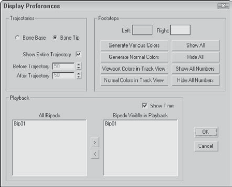
The Preferences option opens the Display Preferences dialog box, shown in Figure 42.5. Using this dialog box, you can set the options for how trajectories and footsteps are displayed, and you can set playback options.
Note
The Biped Display Preferences dialog box is different from the Preference Settings dialog box.
The Track Selection rollout is helpful as you begin to move bipeds and bones about. Its buttons select the biped's Center of Mass (COM) located at the pelvis root. With these buttons, you can key COM tracks for moving and rotating the biped. The buttons are detailed in Table 42.5.
Table 42.5. Biped Track Selection Buttons
Toolbar Button | Name | Description |
|---|---|---|
Body Horizontal | Selects the entire biped and constrains its movement to the horizontal plane | |
Body Vertical | Selects the entire biped and constrains its movement to the vertical plane | |
Body Rotation | Selects the entire biped and allows it to be rotated | |
Lock COM Keying | Allows the Body Horizontal, Body Vertical, and Body Rotation buttons to be used simultaneously | |
Symmetrical | Selects the symmetrical body part and allows both to be transformed together | |
Opposite | Selects the opposite body part and deselects the current one |
The Body Horizontal, Body Vertical, and Body Rotation buttons let you quickly select and move the entire biped in a horizontal or vertical direction or to rotate the entire biped using the common transform gizmos. Body Horizontal keys are displayed in red, Body Vertical keys are displayed in yellow, and Body Rotation keys are displayed in green. If the Lock COM Keying button is enabled, then multiple COM keying tracks can be selected at the same time.
If you select the Body Rotation button and enable the Use Transform Coordinate Center button from the main toolbar, then you can choose the Pick option in the Reference Coordinate System drop-down list on the main toolbar. Once this coordinate system is defined, you can then select a pivot to rotate about, which can be different than the COM. You can select a biped object like the foot or head, an external object like a rock that the biped is jumping over, or even use the Working Pivot.
Note
The ability to rotate the biped about a pivot point that isn't the Center of Mass is new to 3ds Max 2009.
The Symmetrical button instantly selects the symmetrical body part along with the current selection so that both can be transformed together. The Opposite button selects the symmetrical body part to the current selected bone and deselects the current bone. For example, if the right leg bone is selected, then clicking the Opposite button selects the left leg bone instead, and if the right arm bone is selected, then clicking the Symmetrical button also selects the left arm bone so both are selected together.
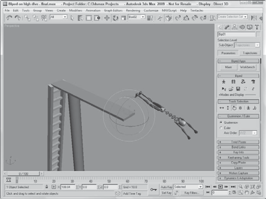
This example shows how you can rotate the entire biped about an external point, which makes moving the biped easy.
To make a biped dive off a diving board, follow these steps:
Open the Biped on high dive.max file from the Chap 42 directory on the DVD. This file includes a simple biped on a high dive. The pivot for the diving board has been repositioned to the end of the board.
Select the biped's upper arm and rotate it so it is pointing upward. Then click the Opposite button in the Track Selection rollout and rotate the other arm upward also.
Select the Body Rotation button in the Track Selection rollout. Then choose the Use Transform Coordinate Center option from the flyout on the main toolbar and choose the Pick option in the Reference Coordinate System drop-down list on the main toolbar. Then click on the diving board.
Then rotate the biped with the Select and Rotate tool. The biped rotates about the end of the diving board, as shown in Figure 42.6.
The Bend Links rollout includes buttons that let you control the rotation and twist of link sets. Table 42.6 lists each of these buttons.
Table 42.6. Biped Track Selection Buttons
Toolbar Button | Name | Description |
|---|---|---|
Bend Links Mode | Transfers rotation information onto children links to create a smooth rotation | |
Twist Links Mode | Allows constrained rotations about the link's local X-axis | |
Twist Individual Mode | Allows rotation of a single link without affecting the other links | |
Smooth Twist Mode | Propagates the rotation of the first and last links to all links to create a smooth twist | |
Zero Twist | Resets the rotation along the local X-axis to 0 | |
Zero All | Resets the rotation along all local axes to 0 |
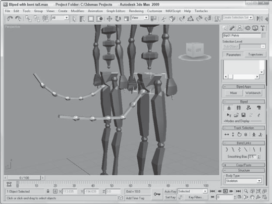
The Bend Links Mode button causes all adjacent bones in a series of links to be adjusted in a realistic manner when one of the bones in the series is moved. Figure 42.7 shows two identical bipeds, each with a rotated tail. The third link in the right biped's tail was rotated with the Bend Links Mode disabled; the left biped has the Bend Links Mode enabled. Notice how the entire tail linkage is affected.
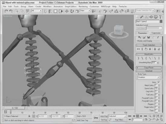
The Twist Links Mode button works in a similar manner to the Bend Links Mode, except it applies to twisting links. The Twist Links Mode button smoothly twists the entire link chain regardless of which link is rotated. The Twist Individual Mode allows only the selected bone to be twisted, and the Smooth Twist Mode bases the twisting of the entire link chain on the rotation of the first or last link. The Smoothing Bias moves the greater area of twisting toward the first link with a value of 0.0 and toward the last link with a value of 1.0.
Figure 42.8 shows how the Twist Links Mode works. The left biped has its fifth spine link rotated, and all other links have gradually been twisted, resulting in a smooth rotation over the whole spine. The right biped has had the same link rotated with the Twist Links Mode turned off. Notice how all the links above have been rotated and those below haven't.
The Copy/Paste rollout includes an interface for saving and reusing different postures, poses, and tracks. Sets of each can be saved into collections. This lets you break up all the poses for a certain character into logical collection sets such as standing poses, sitting poses, action poses, and so on. You can switch among these modes using the buttons at the top of the Copy/Paste rollout. Posture Mode records the position and orientation of a single bone object. Pose Mode records the position and orientation of the entire biped object, and Track Mode records the animation of a single bone object.
Note
The Track button in the Copy/Paste rollout is available only when Figure Mode is disabled.
New collections are created using the Create Collection button. You can rename the collection by typing a new name in the Copy Collections drop-down list at the top of the Copy/Paste rollout. Collections of postures, poses, and tracks can be saved as files using the Save Collection button and reloaded using the Load Collections button found in the Copy/Paste rollout. All saved postures, poses, and tracks are saved using the .cpy extension. Buttons are available for deleting the current collection or all collections. The Max Load Preferences button opens a simple dialog box with options to Keep Existing Collections and Load Collections when a Max file is loaded.
Postures, poses, and tracks can also be copied to the interface using the Copy button. Once copied, they appear in a preview window, as shown for the selected pose in Figure 42.9. All copied postures, poses, and tracks are saved with the Max file. Snapshots shown in the Preview window can be taken from the viewport, taken automatically, not taken at all, or hidden using the buttons located directly under the Preview window.
The selected posture, pose, or track may then be pasted to another bone or biped using the Paste button or using the Paste Opposite button to paste it to the opposite, symmetrical bone. When the Paste Opposite button is used in Pose Mode, the biped that receives a copied pose appears facing the opposite direction to the original. For each mode, there are also buttons to delete the current selection or delete all copies.
The Paste Horizontal, Paste Vertical, and Paste Rotate buttons at the bottom of the Copy/Paste rollout let you paste the COM track keys along with the posture, pose, or track. The By Velocity option pastes the biped's position based on the trajectory of its motion. You can also select to auto-key any TCB and IK values using the Default, Copied, or Interpolated methods.
Biped means a two-footed structure, so creating a four-footed biped is actually an oxymoron. This tutorial should really be called "Creating a biped that is hunched over so its hands are touching the ground," but that would be too long.
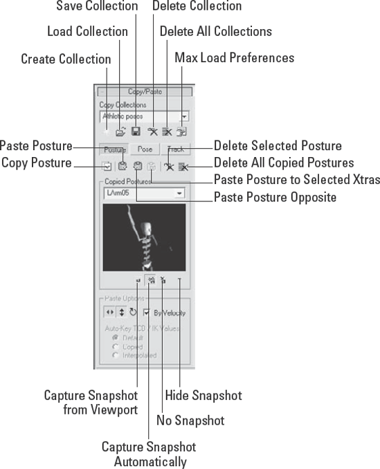
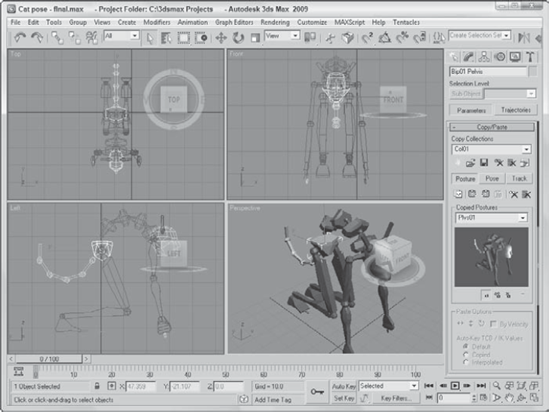
Figure 42.9. A Preview window in the Copy/Paste rollout lets you select the exact pose you want to use.
To create a four-footed biped, follow these steps:
Select the Create

In the Create Biped rollout, set the number of Neck Links to 2, the number of Tail Links to 5, and the Ponytail1 and Ponytail2 Links to 1. Enable the ForeFeet option.
Open the Motion panel, and click the Figure Mode button in the Biped rollout to enter Figure Mode.
In the Bend Links rollout, click the Bend Links Mode button.
Select and rotate the lowest spine bone so the upper torso leans forward.
Select one of the thigh bones, and click the Symmetrical button in the Track Selection rollout to select both thigh bones. Then rotate the thighs to come forward toward the head.
The lower legs will follow.
Select one of the lower leg bones, and click the Symmetrical button in the Track Selection rollout. Then rotate the lower leg bones backward until the feet are in the same vertical position as the hands.
Select one of the ponytail links, and move and rotate it to the position of an ear. Then repeat for the other ponytail link. Make sure that the green ponytail link is on the left side, and the blue one is on the right.
With the Bend Links Mode button selected in the Bend Links rollout, select and rotate the top tail link away from the body. Then click the button again to disable it.
Open the Copy/Paste rollout, click the Create Collection button and select the Pose button. Then click the Copy Pose button to add the pose to the list. Then click the Save Collection button, and save the file as Cat pose.cpy.
Figure 42.10 shows the resulting cat pose.
When it comes time to animate a biped, there are two modes that you can use: Footstep Mode and Freeform Mode. Both have advantages. Footstep Mode is useful for characters that need to walk, run, or jump. It ensures that the feet stay parallel to the ground at all times and can be used to walk over rough terrain. Freeform Mode doesn't constrain the biped and is used for all other actions. Most animation sequences use a combination of both modes.
In Footstep Mode, you animate the movement of the biped by placing footprints for the biped to follow. These footprints can be positioned anywhere within the scene, and the biped automatically creates the motion required to have the biped follow the footprints, including all the realistic secondary motion such as swinging arms. You can also select to have the biped motion be walking, running, or jumping using the buttons in the Footstep Creation rollout.
Note
When you create a Footstep animation sequence, the feet timing is controlled by the footstep icons. If you want to alter or customize the animation, you need to convert the footsteps into keys.
Using the Walk Footstep and Double Support values located under the Walk button, you can set how quickly the footstep animation happens. The Walk Footstep value is the number of frames for which the foot remains within the footstep, and the Double Support value is the number of frames during which both feet are touching the ground.
For the Run and Jump options, the Run Footstep and 2 Feet Down values define the number of frames in which the foot is (or feet are) within the footstep, and the Airborne values define the number of frames in which both feet are in the air.
Footstep Mode is enabled by clicking the Footstep Mode button in the Biped rollout of the Motion panel. This button turns light yellow when enabled and opens several additional rollouts.
Tip
If you look closely at the cursor, you can see which footstep will be created with the next click. If you press the Q key and then reselect the Create Footsteps button, the opposite foot is placed with the first click.
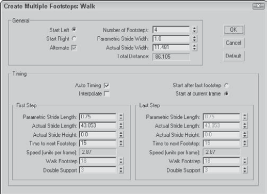
Figure 42.11. The Create Multiple Footsteps dialog box lets you specify details such as Stride Length.
If a footstep is selected, the Footstep Operations rollout includes buttons to deactivate, delete, or copy the selected footstep. If you copy a footstep and then forget what is in the copy buffer, you can enable the Buffer Mode button in the Biped rollout to see the motion of the footstep that is in the buffer.
The Dynamics & Adaptation rollout includes a GravAccel value. This value is used to determine how quickly the body returns to ground during a run or jump cycle. To simulate a character jumping on the moon, reduce the GravAccel value. There are also several Footstep Adapt Locks that can be set.
Although you could easily make your biped dance the two-step, this tutorial has the biped walk a few steps, transition to a run, and then jump on top of a stationary box.
To make biped jump on a box, follow these steps:
Select the Create
Select the Create
Open the Motion panel, and click the Footstep Mode button in the Biped rollout to enter Footstep Mode.
In the Footstep Creation rollout, select the Walk button and click the Create Footsteps button. Then click in the Top viewport to create four footsteps in front of the biped object starting with the right foot.
Choose the Run option in the Footstep Creation rollout, select the Create Footsteps (append) button, and add four more steps that are spread out slightly more than the first steps.
Choose the Jump option in the Footstep Creation rollout, and click the Create Multiple Footsteps button. In the Create Multiple Footsteps dialog box that opens, set the Number of Footsteps to 2, and click OK.
The two footsteps where the biped lands should be in the center of the box object.
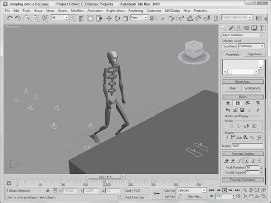
Select and move the final two footsteps upward in the Left viewport to be on top of the Box object.
Click the Create Keys for Inactive Footsteps button in the Footstep Operations rollout to create the keys for the available footsteps.
Click the Play Animation button to see the biped walk, run, and jump on the box.
Figure 42.12 shows the biped as he hops onto a box object.
Clicking the Convert button opens a simple dialog box with the option to generate a keyframe for every frame.
Freeform Mode is enabled by default when none of the other buttons in the Biped rollout are enabled. Using Freeform Mode, you can select and set keys for any of the biped bones, blend several animations into one using Layers, import Motion Capture data, and define Dynamic properties.
The easiest way to set biped keys is to drag the Time Slider to the frame where you want the key to be, select and transform the bone, and then click the Set Key button in the Key Info rollout, shown in Figure 42.13. The Key Info rollout also includes buttons for deleting keys; setting a planted, sliding, or free key; and viewing trajectories.
Warning
The Auto Key and Set Key tools don't work very well with bipeds because they use TCB controllers. Use the biped controls in the Motion panel to set keys instead.

The Key Info rollout also includes several expandable sets of controls, including TCB, IK, Head, Body, and Prop. The TCB controls let you configure the Ease To and Ease From curves of the selected key using a Tension, Continuity, and Bias curve.
The IK controls let you set IK Blend and Ankle Tension values and select a pivot about which to apply the IK solution. The Head section lets you select a Look At Target. The Body controls include a Balance Factor that is used to determine the amount of sway in the biped's motion. The Prop controls lets you select which bone the current prop is linked to for position and rotation.
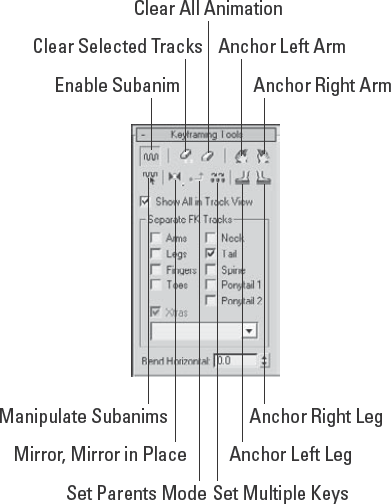
The Keyframing Tools rollout, shown in Figure 42.14, includes several useful buttons for enabling and manipulating subanimations. You can also delete a range of keys or all keys, mirror keys, set multiple keys, and anchor the right hand, left hand, right foot, or left foot. By default, the animation key for each bone is rolled up to its parent, but you can have the key for each individual bone appear as a separate track using the check boxes in the Keyframing Tools rollout.
The Layers rollout lets you layer sets of animations while maintaining existing animations. For example, if a character is animated walking about a scene, then adding a layer with the character's arms held straight up will have the character walk about the scene in the same manner with its arms held up.
After several layers are added onto a biped, you can use the Activate Only Me button to see the animation of a single layer or the Activate All button to view all layer animations.
The Motion Capture rollout lets you load, apply, and manipulate motion capture data. Motion capture data is saved using the .bip file extension.
In addition to creating an animation, you can simply load an existing animation using the Load File button in the Biped rollout. This button opens a file dialog box where you can select the BIP file to load. A preview of the selected biped animation sequence is displayed in the Open dialog box, and you can select to restructure the biped to match the file.
Animation sequences can also be saved using the Save File button. All biped animations are saved using the .bip file extension, and you can select to save any Max objects and List Controllers along with the file.
The Motion Flow Mode button in the Biped rollout opens a rollout of options that let you create a graphical flow of animation sequences that flow together to create a large animation sequence.
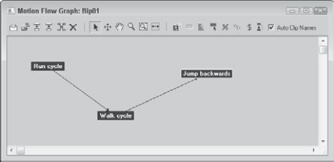
Using the Create Clips button, you can add a node to the graph window. Right-clicking the node lets you open a BIP file. The name of the clip file appears in the node. The Create Transition button can be used to define transitions between nodes, which are represented by arrowed lines. After a transition is defined between two nodes, clicking the Create All Transitions button causes transitions to be created for each defined transition that ensures smooth motion between the various motion clips.
After the nodes of the motion are established, you can use these same nodes to create a motion script that creates the keys needed to view the animation in the viewports. To create a script, click the Define Script button in the Motion Flow rollout and then select the nodes in the order that you want them to appear. Each selected node is added to the rollout list, and dragging the Time Slider displays the biped's motion in the viewports.
Scripts can be saved and loaded using the Load and Save buttons in the Motion Flow rollout. The Motion Flow Graph interface also includes buttons for optimizing, randomizing, and checking all motion clips and their transitions.
After a biped has been animated using footsteps of Freeform keys, you can preview the animation in the viewport using the Biped Playback button found in the Biped rollout. This animates the biped as a stick figure moving through the various keys and is useful for understanding the timing of the biped's motion.
Crowd systems are composed of two helper objects called Crowd and Delegate, but the system can also use other scene objects that act as objects to avoid or follow.
Crowd and Delegate helper objects are created using the Create
Several of the tools that you need to define the crowd system are accessed from the Setup rollout, shown in Figure 42.16.
Note
The various cloning methods are covered in Chapter 8, "Cloning Objects and Creating Object Arrays."
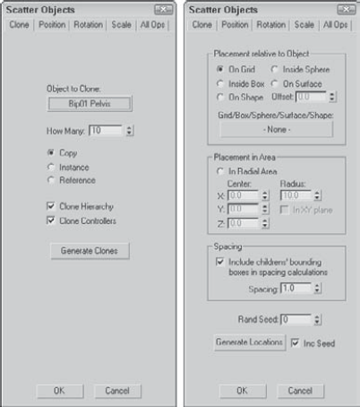
Clicking the Scatter button causes the Scatter Objects dialog box, shown in Figure 42.17, to open. This dialog box includes several panels used to randomize the Position, Rotation, and Scale of the cloned delegates. In the Clone panel, you can select the Object to Clone and How Many clones to create. After the settings are correct, click the Generate Clones button to create the duplicates.

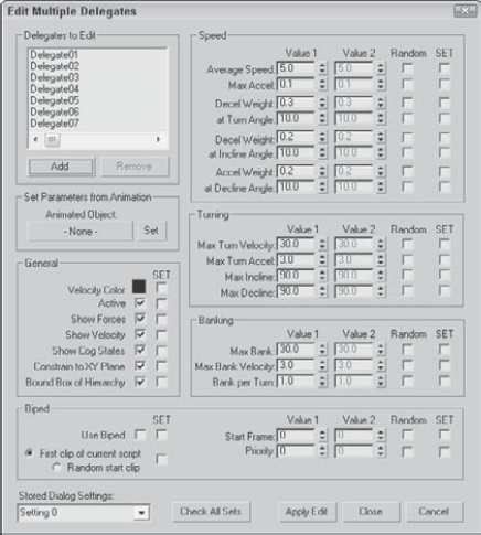
Figure 42.18. The Edit Multiple Delegates dialog box lets you quickly set the parameters of multiple delegates.
In the upper-left corner, you can select the delegate objects to change using the Add button. You can then specify two values for the parameters. If the Random option is specified, the parameter falls somewhere between the two values. You can also save sets of settings using the drop-down list in the lower-left corner of the interface.
Within the Setup rollout of the Crowd object is a New button that lets you add new behaviors that can be used with the crowd system. All behaviors that are added to the crowd system appear in a drop-down list. By typing a new name in the list, you can name each behavior. The available behaviors include the following:
Avoid: Prevents collisions between scene objects and other delegates
Orientation: Controls the direction in which the delegates face
Path Follow: Forces delegates to move only along a designated path
Repel: Forces delegates to move away from a target object
Scripted: Makes a delegate behave using a MAXScript
Seek: Moves delegates toward a target object
Speed Vary: Changes the speed of delegates as they move about the scene
Surface Arrive: Moves delegates toward a surface
Surface Follow: Moves delegates across a surface
Wall Repel: Uses a grid object to repel delegates
Wall Seek: Uses a grid object to attract delegates
Wander: Makes delegates move randomly
When a behavior is selected from the Setup rollout, a custom rollout of parameters for the selected behavior appears. Using these parameters, you can govern how the behavior acts and select which objects are targets.
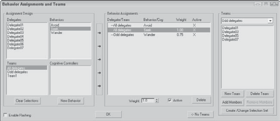
Figure 42.19. The Behavior Assignments and Teams dialog box lets you organize teams of delegates and assign them to behaviors.
All behavior assignments are listed in the center pane, and each assignment can be given a weight. If the delegate has two conflicting behaviors to follow, then it follows the one with the greatest weight value.
The final step in the process is to solve the simulation. This step creates keyframes for all the motion in the scene. To solve the simulation, click the Solve button in the Solve rollout or click the Step Solve button to solve for a single frame at a time. By default, the solution saves keyframes for every frame, but you can increase the Positions and Rotations values to compute the simulation faster.
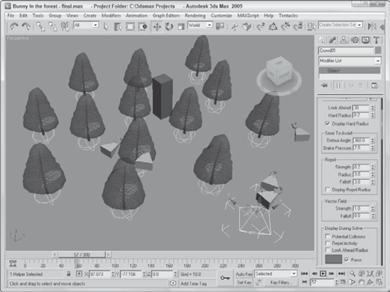
This example uses the delegate primitives linked to rabbit meshes to navigate through a forest. Moving several objects through an array of objects can be time consuming when done by hand, but the Crowd system makes it easy.
To move a group of rabbit delegates through an array of trees, follow these steps:
Open the Bunny in the forest.max file from the Chap 42 directory on the DVD. This file includes several pine trees and a bunch of bunnies.
Select the Create
Select the Create
Select the crowd object, click the New button in the Setup rollout of the Modify panel, select the Avoid behavior, and name it Avoid trees. In the Avoid Behavior rollout, click the Multiple Selection button. In the Select dialog box that appears, choose all tree objects and click the Select button. Enable the Display Hard Radius button, and then decrease the Hard Radius value to 0.2 so that bunnies can travel through the trees.
Click the New button again. This time, select the Seek behavior and name it Seek hole. In the Seek Behavior rollout, click the None button and choose the red box object that represents the hole.
In the Setup rollout, click the Behavior Assignment button to open the Behavior Assignment and Teams dialog box. Click the New Team button, select all delegate objects, and click OK. Then select the Team0 team and the Avoid cubes behavior, and click the center New Assignment button (the long, thin button with the right-pointing arrows). Select the Team0 team again with the Seek goal behavior, and click the New Assignment button again. Both assignments are listed in the center pane; click OK.
Set the Solve time equal to the animation length of 300 frames. In the Solve rollout, click the Solve button.
The crowd system solves the movement of all delegates as they move toward the goal.
Click the Play Animation button to see the resulting solution.
Figure 42.20 shows the position of the delegates after the simulation has ended. Notice the random position of the various delegates.
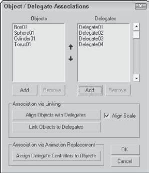
Working with delegates is simple enough, but you probably don't have much need for an animation of several pyramids moving about the scene. The real advantage of the crowd system comes when you're working with objects and bipeds.
Click the Add buttons to add Objects and Delegates to their respective lists. The arrow buttons between the columns can be used to reorder items in the list. After all objects are matched with their correct delegates, click the Align Objects button or the Link Objects button to complete the linking.
This chapter serves as an introduction to Character Studio and covers all aspects of working with bipeds. The Crowd features of Character Studio are useful for animating the motion of delegates following specified behaviors. The following topics were covered:
Learning the basic workflow for creating characters
Creating and editing biped skeletons
Animating bipeds using footsteps and freeform keys
Creating crowds with helper objects
Assigning behaviors
Using bipeds with crowds
Whether you're using a custom rig or a Biped, the next step is to begin the skinning process, which is covered next. Skinning surrounds the skeleton with a mesh skin and matches the way the skin aligns and moves with the underlying rig.