
The need to bring files created by other CAD applications into Inventor is common to many Inventor users. For instance, if you design components that others use in their designs, you might need to output files to a standard format so that others can use them with a different software package. Or, if you are a manufacturing "job shop," you may receive many different file formats from customers that you need to bring into Inventor. The ability to open and translate files into Inventor 2010 has been improved with the inclusion of even more native file format translators as well as the ability to open and save neutral file formats.
In this chapter, you'll learn to:
Import and export geometry
Use Inventor file translators
Work with imported data
Work with Design Review markups
Essentially, three data types make up a 3D model: curves or wires, surfaces, and solids. Wire frame models composed of only curves lack volume but have a size and shape. A surface model, on the other hand, is composed of curves that define the surfaces. A solid model is composed of curves, which define surfaces, which in turn define the solid. Understanding the hierarchy of geometry data will help you understand the translation issues that can occur when translating from one of these data types to another.
Within the category of curves and wires, there are different ways in which wires and curves are defined. If you are translating files that represent wires and curves as Non-Uniform Rational B-Splines (NURBS) to a format that represents wires and curves as simpler basis splines (B-splines), then there might be something lost in translation. Likewise, when you translate a surface model, if the surface normal were to get reversed (think positive vs. negative), then you will have translation issues. And so it is with translating solids; if a solid model is translated so that a gap is formed where two surfaces meet, then translation may not be complete.
Translation of curves, surfaces, and solids occur between different packages because software packages use different methods of geometric accuracy. Accuracy controls such things as how close two points in space are before being considered a single point or how close two edges can be before they are considered connected, and so on.
To help with translating from one software package that solves curves using method A to software that uses method B, you can create an intermediate or neutral file. Common neutral file formats include IGES (Initial Graphic Exchange Specification), STEP (Standard for the Exchange of Product), SAT (Standard ACIS Text), and others.
When an AutoCAD DWG file is imported into Inventor, the file is translated into an Autodesk Inventor part, assembly, and/or drawing file, based on the import settings. The original AutoCAD file is not changed. When exported from Inventor to a DWG, a file is translated into AutoCAD objects. The translated DWG is not linked to the Inventor file from which it was created. Instead, the DWG data is fully editable within AutoCAD.
To import a DWG file, follow these steps:
Click Open on the Get Started tab.
Set the Files Of Type drop-down to AutoCAD Drawings (*.dwg).
Select the DWG file you are going to import.
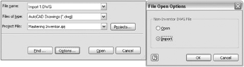
Click the Options button and choose Import. (If you are translating a number of DWG files, you can set Import to be the default by clicking the Tools tab, then selecting the Application Options button, and choosing the Drawing tab.)
Once you've selected Import, as shown in Figure 14.1, click OK.
This returns you to the Open dialog box, where you will click the Open button to start the DWG/DXF File Wizard. Note the Configuration drop-down box.
If you have an import configuration already saved, you can specify it now and click Finish. If you have not yet created a configuration template, click Next to go to the Import Destination Options dialog box.
You need to consider a number of options when importing DWG files, depending on the DWG data input and the intended translation output. The following sections discuss these considerations in relation to the import options.
If the AutoCAD DWG has 3D solids, you can check the 3D Solids check box to translate them into Inventor part files. Use the Solids To Single Part File check box if you want multibody solids to be translated into an Inventor part file. Leave this option unchecked if you want each solid body in the DWG to be created as an individual Inventor part file and automatically placed in an Inventor assembly. Figure 14.2 shows the import options for 3D solids.
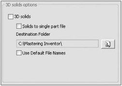
Set the destination folder to a path in which you want to have the part files created and choose Use Default File Names to allow Inventor to name the resulting part files automatically. If you choose this option, the new Inventor parts will be given a name based on the DWG name and be incremented by a value of 1. For instance, if the DWG is named Engine.dwg, then each solid in the DWG will be named Engine1.ipt, Engine2.ipt, Engine3.ipt, and so on. If left unchecked, each solid in the DWG will be named Part1.ipt, Part2.ipt, Part3.ipt, and so on.
If the DWG contains only 2D data, then you can leave the 3D Solids check box deselected and turn your attention to the Destination For 2D Data area of the dialog box, as shown in Figure 14.3. Selecting the New Drawing radio button translates the DWG data to a new Inventor DWG or IDW. If you check Promote Dimensions To Sketch, the 2D data is placed in a draft view that is created in the Inventor drawing.
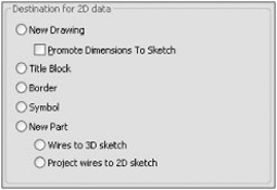
You can use the Title Block radio button to convert an AutoCAD title block DWG into an Inventor title block. When doing this, be sure to click the mapping options to set the layer and font mapping options, as shown in Figure 14.4. You can click the Symbols radio button to translate the 2D data into a sketched symbol for use in an Inventor DWG or IDW file. Click the New Part radio button to translate AutoCAD 2D data into a new IPT sketch. Choose between creating a 3D or 2D sketch within the file.
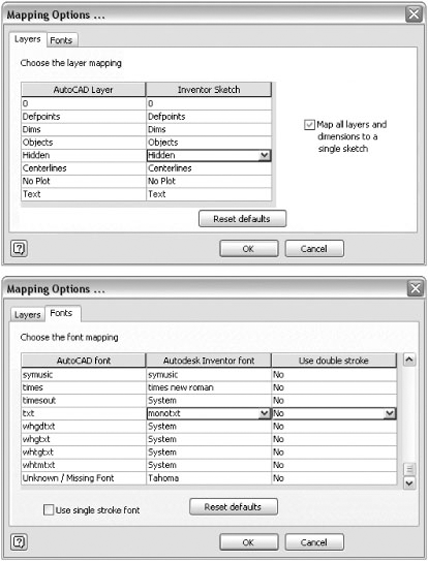
Inventor has both a decimal and a fractional unit style for dimensions. When dimensions are translated, if Inventor detects that the AutoCAD file employs a scientific, decimal, engineering, or Windows Desktop style, those styles are converted to decimal style. Fraction and architectural are mapped to fractional style.
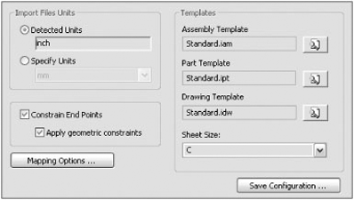
Whether importing to 2D or 3D, you will use the templates area to specify which template to use for each of the file types to translate to. In the Import Files Units area, you can specify the units if they do not match the units that Inventor detects from the AutoCAD file. The detected unit is based on the INSUNITS system variable in the DWG file.
You can use the Constrain End Points and Apply Geometric Constraints check boxes to allow Inventor to place constraints on sketch entities when it can. Endpoints found to be coincident will be given a coincident constraint; lines found to be parallel will be given parallel constraints; and so on.
Once all these options are configured, you can click the Save Configurations button, as shown in Figure 14.5, to write out a file to use the next time you convert a DWG file. Doing this allows you to convert files more accurately and more quickly.
When all the configuration settings have been made and saved, click Finish to start the import process. Inventor will create the new files based on your configurations and leave the files open in the current Inventor session.
Mechanical Desktop (MDT) files can be imported into Inventor part and assembly files. If the source files contain geometry or features that are not recognized in Inventor, they are omitted, and the missing data is noted in the browser or the translation log file. No links are maintained to the existing MDT files. You must have MDT on your computer to import files into Inventor. Note that the AutoCAD Inventor suite does not ship with MDT. If you have a need to use MDT for translation, the 2009 version can be downloaded from the Autodesk website or you can purchase or request installation media. MDT 2009 is the last version that Autodesk will release.
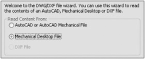
You can import MDT DWG files using the Options button in the Open dialog box just as you would a regular DWG. However, if Inventor detects that the file is an MDT file, you are given the option to read the data as an MDT file or as an AutoCAD or AutoCAD mechanical file, as shown in Figure 14.6.
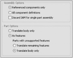
Although many of the options for template, units, and configuration settings are the same as previously described for regular DWG files, the assembly and part options are specific to MDT files, as shown in Figure 14.7.
Consider the following items when migrating MDT files to Inventor:
Broken views, base section views, and breakout section views from MDT will be turned into base views.
Exploded views will become unexploded views (no tweaks applied).
Importing discards (AMPARDIMS) from MDT automatically creates associative model dimensions in Inventor.
If Move With Parent is selected in an MDT file, Inventor aligns all views according to the view type.
If a parent view is missing in an MDT file, a child view is not created in Inventor.
Inventor centerlines and center marks are automatically generated during translation; therefore, they might not be the same as in the MDT file.
Radial section views have broken alignment in Inventor.
In addition to importing MDT files one at a time, you can use the Inventor Task Scheduler to batch the translation from MDT to Inventor. It is important to ensure that the MDT files are migrated to the latest version of MDT before attempting to translate them into Inventor files.
STEP (Standard for the Exchange of Product) and IGES (Initial Graphic Exchange Specification) are nonproprietary file formats to write data to, in order to exchange data among proprietary software. When opening a STEP or IGES file in Inventor, one part file will be created if the file contains only one part body; otherwise, you can create multiple Inventor part files placed within an assembly file.
Although no links are maintained between the original STEP or IGES file and the Inventor files created from them, when importing an updated STEP or IGES file, Inventor updates the geometry and maintains all modeling constraints and features applied to that STEP or IGES file.
To import a STEP or IGES file, follow these steps:
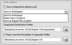
In the Import Options dialog, you can choose from three save options:
- Save In Workspace
Writes the files to the Workspace folder defined in your current project file (see Chapter 2 for more on projects and workspaces). The files are saved as Inventor files during the import process.
- Select Save Location
Allows you to specify where the resulting Inventor files will be saved. If the translated file contains separate solid bodies, you can configure the import to save those files to one location and the top-level assembly file to another location.
- Save At Import File Location
Writes the resulting Inventor file(s) to the same location as the original file. Figure 14.8 shows the Import Save options.
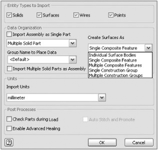
In the Entities To Import area, use the selection buttons to specify the inclusion of solids, surfaces, wires, and points in the import action. Click the Import Assembly As Single Part check box to turn a multibody STEP or IGES into a single-part file. Then choose from one of two options:
- Single Composite Feature
This allows you to import the assembly as a single composite feature into a single-part file.
- Multiple Solid Part
With this option, you can import the assembly as individual solid bodies into a single-part file.
Click the Import Multiple Solid Parts As Assembly check box to turn a multibody STEP or IGES into individual part files. When imported, the new Inventor parts will be given a name based on the filename and incremented by a value of 1. For instance, if an IGES were named 4278_T.igs, then the Inventor parts will be named 4278_T 1.ipt, 4278_T 2.ipt, 4278_T 3.ipt, and so on.
If you leave both of those check boxes deselected, you can specify how surface objects will be translated:
- Individual Surface Bodies
Imports each surface as a single surface body all contained in a single-part file.
- Single Composite Feature
Imports surfaces as a single composite all contained in a single-part file.
- Multiple Composite Features
Imports surfaces as multiple composites all contained in a single-part file. Composites are created for each level, layer, or group, according to the Create From information specified.
- Single Construction Group
Imports surfaces as a single group in the construction environment of a single-part file.
- Multiple Construction Groups
Imports surfaces as multiple groups in the construction environment of a single-part file. Construction groups are created for each level, layer, or group, according to the Create From information specified.
A composite is a collection of surfaces, as opposed to a single quilt of surfaces. A composite can consist of any combination of single- or multiple-faced surfaces or closed volume surfaces. Often these surfaces will not be connected even if they appear to be. Composites can be used when many surfaces are imported as an expedient way of getting surface data into Inventor for reference or inspection.
You can also specify which units the imported geometry will be converted to, and the post-process options as listed here:
- Check Parts During Load
This performs a quality check on the imported data. Bad data is marked with a symbol in the browser and any remaining data is not checked. If the parts are determined not to have any errors, they are marked with a green check mark in the browser. Checking parts can significantly increase the time required to translate a file.
- Auto Stitch And Promote
This stitches surfaces into a quilt or solid, when possible. If the stitch results in a single body, it is promoted out of the construction environment; otherwise it remains in the construction environment.
- Enable Advanced Healing
This allows small alterations in the surface geometry in order to stitch the surfaces.
Figure 14.9 shows the STEP and IGES options.
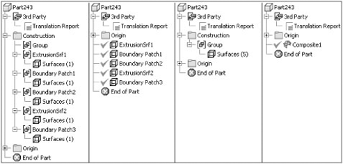
Figure 14.10 shows the same file imported in four different ways:
- Far Left
Data is placed into Multiple Construction Groups.
- Middle Left
Data is placed into Multiple Composite Features.
- Middle Right
- Far Right
Data is placed into a Single Composite Feature.
Many Inventor users prefer to send and receive STEP files to and from vendors or clients because they find STEP files import better than other file formats. Here is a list of attributes that make STEP a popular choice:
STEP files can retain the original part names when importing to an assembly.
STEP creates instances for duplicated parts. If you are sent a STEP of an assembly created in another software package and that assembly has 12 instances of a certain screw size, Inventor will typically create just one file for the screw and instance it 12 times, as opposed to creating 12 different files.
STEP files can maintain assembly hierarchy, meaning that subassembly structure can be translated. In other formats, assemblies may be translated with all parts at the top-level assembly.
STEP translates part colors, whereas other formats generally do not contain the information needed to carry part colors across different platforms.
STEP format is governed independently and is not tied to a particular modeling kernel; as a result, it is often considered somewhat of a more standard format.
To export a file as a STEP, click the Inventor button
To export a file as an IGES, click the Inventor button
SAT (Standard ACIS Text) files are written in the standard file exchange format for the ACIS solid modeling kernel. To import a SAT file, follow these steps:
In the Import Options dialog box, you can choose from three save options:
- Save In Workspace
Writes the files to the Workspace folder defined in your current project file (see Chapter 2 for more on projects and workspaces). The files are saved as Inventor files during the import process.
- Select Save Location
Allows you to specify where the resulting Inventor files will be saved. If the translated file contains separate solid bodies, you can configure the import to save those files to one location and the top-level assembly file to another location.
- Save At Import File Location
Writes the resulting Inventor file(s) to the same location as the original file.
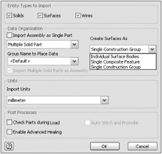
In the Entities To Import area, use the selection buttons to specify the inclusion of solids, surfaces, and wires in the import action. Use the Import Assembly As Single Part check box option to turn a multibody SAT into a single-part file. Then choose from one of two options:
- Single Composite Feature
Imports the assembly as a single composite feature into a single-part file.
- Multiple Solid Part
Imports the assembly as individual solid bodies into a single-part file.
If you leave this check box deselected, you can specify how surface objects will be translated:
- Individual Surface Bodies
Imports surfaces as an individual surface all contained in a single-part file.
- Single Composite Feature
Imports surfaces as a single composite all contained in a single-part file.
- Single Construction Group
Imports surfaces as a single group in the construction environment of a single part file.
Some CAD software outputs SAT files in a default unit without regard for the units used to create the original file. You can specify which units the imported geometry will be converted to, as well as the post-process options listed here:
- Check Parts During Load
This option performs a quality check on the imported data. Bad data is marked with a symbol in the browser and any remaining data is not checked. If the parts are determined not to have any errors, they are marked with a green check mark in the browser. Checking parts can significantly increase the time required to translate files.
- Auto Stitch And Promote
This option stitches surfaces into a quilt or solid, when possible. If the stitch results in a single body it is promoted out of the construction environment; otherwise, it remains in the construction environment.
- Enable Advanced Healing
This option allows small alterations in the surface geometry in order to stitch the surfaces.
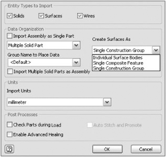
Figure 14.11 shows the SAT import options.
To export a file as a SAT, click the Inventor button
With Inventor, you can access files from other CAD systems without downloading an add-in or translating the files to an intermediate format such as STEP, IGES, or SAT. Instead, you simply open the file, and Inventor will translate the file into an Inventor file on the fly. You can translate all of the file types in the following list by clicking Open on the Get Started tab and then setting the Files Of Type drop-down to the appropriate type. Once the file type is selected, click the Option button to configure the import options.
In the Import Options dialog box, you can choose from three save options:
- Save In Workspace
Writes the files to the Workspace folder defined in your current project file (see Chapter 2 for more on projects and workspaces). The files are saved as Inventor files during the import process.
- Select Save Location
Allows you to specify where the resulting Inventor files will be saved. If the translated file contains separate solid bodies, you can configure the import to save those files to one location and the top-level assembly file to another location.
- Save At Import File Location
Writes the resulting Inventor file(s) to the same location as the original file.
Figure 14.12 shows the import save options.
For each of these file types, you can specify which units the imported geometry will be converted to as well as the post-process options listed here:
- Check Parts During Load
This option performs a quality check on the imported data. Bad data is marked with a symbol in the browser and any remaining data is not checked. If the parts are determined not to have any errors, they are marked with a green check mark in the browser. Checking parts can significantly increase the time required to translate files.
- Auto Stitch And Promote
This option stitches surfaces into a quilt or solid, when possible. If the stitch results in a single body, it is promoted out of the construction environment; otherwise, it remains in the construction environment.
- Enable Advanced Healing
This option allows small alterations in the surface geometry in order to stitch the surfaces.

When importing CATIA V5 files, you can choose between solids, surfaces, wires, and points. To open CATIA files, follow these steps:
Click Open on the Get Started tab.
Set the Files Of Type drop-down to CATIA V5 Files (*.CATPart;*.CATProduct).
Select the CATIA file you want to open and click the Options button.
Figure 14.13 shows the import options for CATIA files.
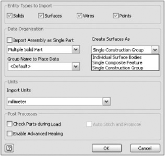
In the Entities To Import area, use the selection buttons to specify the inclusion of solids, surfaces, wires, and points in the import action. Use the Import Assembly As Single Part check box to turn a multibody CATIA file into a single-part file. Then choose from one of two options:
- Single Composite Feature
Imports the assembly as a single composite feature into a single-part file.
- Multiple Solid Part
Imports the assembly as individual solid bodies into a single-part file.
If you leave this check box deselected, you can specify how surface objects will be translated:
- Individual Surface Bodies
Imports surfaces as an individual surface all contained in a single-part file.
- Single Composite Feature
Imports surfaces as a single composite all contained in a single-part file.
- Single Construction Group
Imports surfaces as a single group in the construction environment of a single-part file.
To open models created in Pro/ENGINEER, follow these steps:
Select Open from the Get Started tab.
Set the Files Of Type drop-down to Pro/ENGINEER (*.prt*; *.asm*) or (*.g) or (*.neu*).
Select the Pro/ENGINEER file you want to open, and click the Options button.
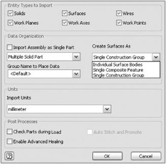
Figure 14.14 shows the import options for Pro/ENGINEER files.
In the Entities To Import area, use the selection buttons to specify the inclusion of solids, surfaces, wires, work planes, work axes, and work points in the import action. Use the Import Assembly As Single Part check box to turn a multibody Pro/ENGINEER file into a single-part file. Then choose from one of two options:
- Single Composite Feature
Imports the assembly as a single composite feature into a single part file.
- Multiple Solid Part
Imports the assembly as individual solid bodies into a single part file.
If you leave this check box deselected, you can specify how surface objects will be translated:
- Individual Surface Bodies
Imports surfaces as an individual surface all contained in a single-part file.
- Single Composite Feature
Imports surfaces as a single composite all contained in a single-part file.
- Single Construction Group
Imports surfaces as a single group in the construction environment of a single-part file.
To import Pro/ENGINEER parts or assemblies that contain instances of family tables, the accelerator files (*.xpr or *.xas) must be saved independently of the Pro/ENGINEER part and assembly files.
When the files are opened in Inventor, they will consist of a base solid, work features, and a translation report. You can then add features to the base solid using standard Inventor part-modeling tools. Figure 14.15 shows an imported Pro/ENGINEER file with translated work features.
You can access Unigraphics and Parasolids files in the same way you would Pro/ENGINEER files. To do so, follow these steps:
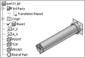
Figure 14.16 shows the Parasolids import options.

In the Entities To Import area, use the selection buttons to specify the inclusion of solids, surfaces, and points in the import action. Use the Import Assembly As Single Part check box to turn a multibody Parasolid file into a single-part file. Then choose from one of two options:
- Single Composite Feature
Imports the assembly as a single composite feature into a single-part file.
- Multiple Solid Part
Imports the assembly as individual solid bodies into a single-part file.
Use the Import Multiple Solid Parts As Assembly check box to turn a multibody Parasolid file into individual part files. When imported, the new Inventor parts will be given a name based on the name of the original files.
If you leave both of those check boxes deselected, you can specify how surface objects will be translated. Here are the options:
- Individual Surface Bodies
Imports surfaces as individual surfaces all contained in a single-part file.
- Single Composite Feature
Imports surfaces as a single composite all contained in a single-part file.
- Single Construction Group
Imports surfaces as a single group in the construction environment of a single-part file.
To open models created in SolidWorks, follow these steps:
Click Open on the Get Started tab, and set the Files Of Type drop-down to SolidWorks (*.prt, *.sldpart, *.asm, and *.sldasm).
Select the SolidWorks file you want to open, and click the Options button.
Figure 14.17 shows the import options.
In the Entities To Import area, use the selection buttons to specify the inclusion of solids and surfaces in the import action. Use the Import Assembly As Single Part check box to turn a multibody SolidWorks file into a single-part file. Then choose from one of two options:
- Single Composite Feature
Imports the assembly as a single composite feature into a single-part file.
- Multiple Solid Part
Imports the assembly as individual solid bodies into a single-part file.
Use the Import Multiple Solid Parts As Assembly check box to turn a multibody SolidWorks file into individual part files. When imported, the new Inventor parts will be given a name based on the name of the original files.
If you leave both of those check boxes deselected, you can specify how surface objects will be translated. Here are the options:
- Individual Surface Bodies
Imports surfaces as an individual surface all contained in a single-part file.
- Single Composite Feature
Imports surfaces as a single composite all contained in a single-part file.
- Single Construction Group
Imports surfaces as a single group in the construction environment of a single-part file.
Intermediate Data Format (IDF) is the standard data exchange format for transferring printed circuit assembly (PCA) files between printed circuit board (PCB) layouts and mechanical design programs. You can access IDF board files by clicking Open on the Get Started tab and setting the Files Of Type drop-down to IDF Board Files (*.brd, *.emn, *.bdf, and *.idb).
IDF board files can be imported into Inventor as assembly or part files. When brought in as an assembly, board components are translated into individual parts, contained in the new assembly. When imported as a part, the board components are translated into sketches and features. Inventor will translate IDF outlines, keepouts, group areas, drilled holes, and components.
Part files are automatically named based on the information in the existing board file. Once imported, the files can be placed into Inventor assemblies and detailed in Inventor drawings just as you would any other Inventor model. Figure 14.18 shows the IDF import options. You are presented with this dialog box automatically when you open an IDF board file.

So far you have learned about importing and translating files into Inventor using the Open dialog box to convert files into Inventor files. You can also access most of these file types in the assembly environment and place them straight into your Inventor assembly file just as you would any other model.
To place a non-Inventor component into an Inventor assembly, click the Place Components icon in the Assembly panel. In the Open dialog box, select the file type of the component you intend to place, or set the file type to All Files. Select the file, and then click the Options button. Configure the options as required, and click OK. Click Open to translate, and place the component into the assembly.
In a perfect world, you would not need to import or export data at all. Instead, all files would exist in one perfect, universal file format. Of course, this perfect world does not exist, and you are probably required to import files created in another program from time to time. In a near-perfect world, imported data would always come in healthy and without any problems. Of course, that is rarely the case.
Instead, importing data can sometimes be a struggle. Typically the biggest struggles come with importing surface models. Inventor provides a construction environment for repairing poorly translated surfaces. Once repaired, imported surfaces must be promoted to the part environment for use in parametric modeling or so they can be seen in an assembly.
If you choose Auto Stitch And Promote when importing a surface IGES or STEP, Inventor will attempt to automatically promote imported surfaces to the part environment. If surfaces cannot be promoted, they are left in the construction environment. With Auto Stitch And Promote turned off, the surfaces open directly in the construction environment.
If a construction folder exists in the browser, you can right-click it and choose Edit Construction to enter the construction environment. If no Construction folder is present, you must copy composite features to the Construction folder. You can do this by right-clicking the composite in the browser and choosing Copy To Construction.
To examine the construction tools in action, follow these steps:
On the Get Started tab, click the Open button.
Set the file type drop-down to IGES.
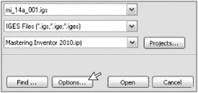
Browse for and select the file named
mi_14a_001.igslocated in the Chapter 14 directory of the Mastering Inventor 2010 folder.Click the Options button, as shown in Figure 14.19.
In the Options dialog box, ensure that all the Entities To Import buttons are selected.
Set the Create Surfaces As drop-down to Multiple Construction Groups.
Ensure that the Auto Stitch And Promote check box is not selected. You can leave all the other settings at their defaults.
When the specified settings match Figure 14.20, click the OK button, and then click Open.
Once the file is open, examine the Model browser for the presence of the Construction folder. Expand this folder, and verify that there are 90 surfaces in one group within the folder. If you do not see this, check the import options shown in Figure 14.20 and ensure you have set them as shown. In particular, ensure the Autostitch And Promote option is not selected.
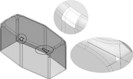
Notice you cannot select the surfaces in the graphics area. This is because all the surfaces reside in the construction environment. Note that had you selected the Auto Stitch And Promote option, the surfaces might have been promoted from the construction environment automatically. Depending on the quality of the surfaces, you might be required to stitch and promote surfaces manually, as you will here. Examine the model, and notice that there are some missing surfaces. You will need to repair these surfaces in order to promote them and turn this part into a solid. Figure 14.21 shows the location of the missing and errant surfaces.
To activate the construction environment, right-click the Construction folder in the browser and choose Edit Construction. This opens the Construction tool panel.
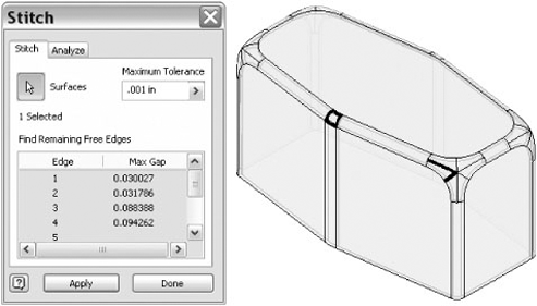
Select the Stitch Surface tool from the Construction tab, and create a window selection of all of the surfaces on-screen.
Enter 0.001 in in the Maximum Tolerance field, and click Apply.
You will see the 90 surfaces stitched into a single quilted surface. The gaps created by the missing and errant surfaces are also highlighted, and the remaining free edges are reported in the Stitch dialog box, as shown in Figure 14.22.
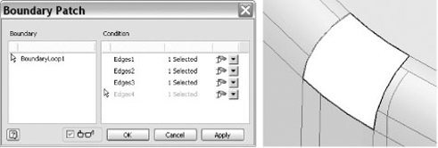
Next you will use the Boundary Patch tool to create a surface to fill in one of the gaps.
Click Done in the Stitch dialog box and zoom in to the area indicated with a circle in Figure 14.21. Notice the missing surface.
Choose Boundary Patch from the Construction tab. Select the four edges as indicated in Figure 14.23, and then click OK.
Notice in the browser there are now two surfaces in the Group folder. Using the Stitch tool, select the new surface and any face on the rest of the other surface to stitch the two together.
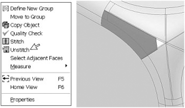
Zoom to the corner area that was indicated with an ellipse back in Figure 14.21, and notice the missing errant surface.
You'll notice two of the surfaces extend beyond the adjacent surfaces and the corner of the surface is cut short, leaving a gap. To resolve this, you will first select the surface and choose Unstitch, as shown in Figure 14.24.
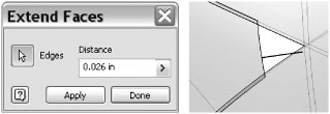
To fill the gap in the surface, select the Extend Faces tool from the Construction tab, and choose the edge, as shown in Figure 14.25. Enter 0.026 in for the distance, and click Apply. This will extend the surface over the existing gap.
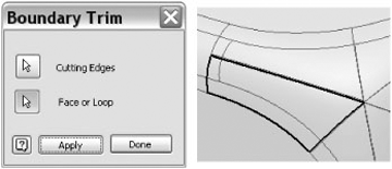
Now you need to trim the surface edges to the adjacent surfaces. To do this, select the Boundary Trim tool on the Construction tab, then select the edges of the adjacent faces, as shown in Figure 14.26. Finally, choose the unstitched surface, and click Apply.
Once the surface is trimmed, click the Stitch tool and select the both the trimmed surface and the existing surface quilt (you can window-select the entire part to do this). Click Apply and then click Done.
When you do, you will see the group switch from Surfaces (2) to Solid (1), indicating that you have a surface set that is ready to be promoted to a solid.
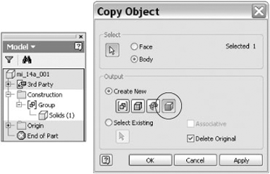
Choose Copy Object from the Construction tab, and select Solids (1) from the model tree. Set the Output setting to be solids by clicking the icon, and then click OK, as shown in Figure 14.27.

You will now have a base solid in the Model browser, as well as the Construction folder and the third-party translation report. Click the Finish Construction button to exit the construction group, and then you can remove the translation report (in the 3rd Party folder) and Construction folder by right-clicking them in the browser and choosing Delete.
You can add features to the base solid by sketching any of the desired surfaces and using the standard Inventor part-modeling tools. To add features, follow these steps:
On the Get Started tab, click the Open button.
Browse for and select the file named
mi_14a_003.iptlocated in the Chapter 14 directory of the Mastering Inventor 2010 folder.Right-click on the Base1 feature in the browser and choose Edit Solid.
Expand the Origin folder in the Model browser, right-click on the YZ plane, and choose Visibility.
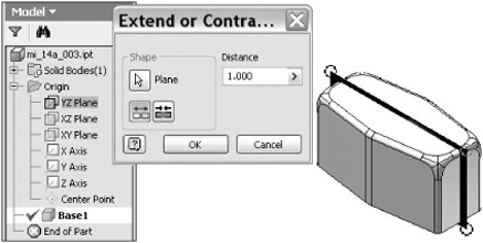
Click the Extend/Contract Body icon on the Edit Base Solid tab.
For the plane, click on the edge of the YZ plane in the graphics area.
Enter a distance of 1.0 inch in the Distance box and click OK, as shown in Figure 14.28.
You can also use the Move Face tool to adjust a base solid. To adjust the depth of this part, click the Move Face icon on the Edit Base Solid tab, and select the bottom face of the part.
Enter 0.25 in in the Distance box, click the Flip Direction button so that your preview looks like Figure 14.29, and then click OK.
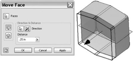
You will see the depth of the part increase. Had you not clicked the Direction button, you would have decreased the depth of the part. You can click the Finish Base Solid button to exit the solid editing tools. Feel free to experiment with adding sketches and features to the base solid as well.
Autodesk Design Review offers Inventor users a simple and effective way to view and mark up both 2D and 3D DWF files. Design Web Format (DWF) files are lightweight versions of your Inventor files you can publish from Inventor and email to a collaborator to be viewed and redlined with Autodesk Design Review (ADR). Non-Inventor users can download and install ADR free of charge from the Autodesk website.
The DWF markup process begins from within Inventor where you will publish a DWF from your Inventor files. Once the DWF is published, it is sent to the reviewer and marked up with ADR. You can then bring those markups into your Inventor file and change the status of a markup, add comments, or accept the markup. You have the additional choice of publishing to DWFx format, allowing reviewers to access the file directly through Internet Explorer 7.0 or Windows Vista.
A typically DWF markup process is as follows:
Publish: You write out the DWF file from Inventor 2D and/or 3D files.
Receive: The reviewer receives the DWF file from you and opens it with ADR to check for errors and omissions.
Review: The reviewer can comment on and mark up the DWF file using callouts, text blocks, shapes, dimensions, stamps, and custom symbols. Then they save those markups to the DWF file.
Return: The reviewer then sends the markups back to you for your review.
Revise: You load the marked-up DWF into Inventor and revise the Inventor files as required.
Republish: After revising, you write out the DWF file from Inventor 2D and/or 3D files again.
With the file you intend to publish open in Inventor, click the Inventor button
- Express
Publishes only the active sheet without the 3D model.
- Complete
Publishes all sheets and all 3D models except sheets excluded from printing.
- Custom
Chooses sheets and 3D models to publish, depending on the type of file you are publishing. Extra tabs appear in the Publish dialog box for each file type as required. Here's what's included for each file type when you are using the Custom option:
- Drawing files
The DWF or DWFx file includes all sheets and tables, as well as the complete referenced 3D models.
- Assembly files
The following assembly options are available:
The DWF or DWFx file includes the assembly with view and positional representations, as well as enabled BOM views.
The DWF or DWFx file includes all members and the iAssembly table with view and positional representations.
The DWF or DWFx file includes the assembly with view and positional representations, as well as enabled BOM views.
The DWF or DWFx file includes the assembly with view and positional representations, as well as enabled BOM views, weld beads, and weld symbols.
The DWF or DWFx file includes the assembly with view and positional representations, as well as enabled BOM views.
When an assembly is at any other LOD other then the master, only that LOD is published to the DWF or DWFx. All view and positional representations, as well as enabled BOM views, are also published.
- Part files
The following part options are available:
The DWF or DWFx file includes only the part model.
The DWF or DWFx file includes the folded model and flat pattern (if one exists).
The DWF or DWFx file includes all iPart members and the iPart table.
The DWF or DWFx file includes only the iPart model.
The DWF or DWFx file includes the model with stress/constraint indicators as well as a stress scale.
- Presentation files
The DWF or DWFx file includes the presentation views, animations, and assembly instructions, as well as the complete assembly.
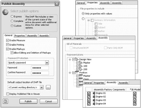
DWF or DWFx files can be published with the ability to measure, print, and enable and disable markups. They can be password protected for security also. Figure 14.30 shows the publish options for an iAssembly factory.
Once you choose the appropriate options, click Publish to specify either the DWF or DWFx format, and specify a location to create the file. The resulting file can be opened in Design Review to create markups.
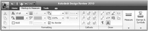
Once a DWF or DWFx file is open in Design Review, you can create markups in the form of callouts, text blocks, shapes, stamps, custom symbols, and measurements. Figure 14.31 shows the Markup and Measure tab.
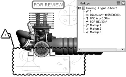
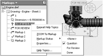
When markups are created, they are listed in the Markups palettes and organized by the sheet upon which they reside. Most markups contain the following collection of properties: Status, Notes, History, Created, Creator, Label, Modified, and Sheet. Drawn markups such as lines do not have properties.
Each markup can have its own status. The status can be <None>, For Review, Question, or Done. When you click a markup in the Markups palettes, the screen will zoom to the markup at the same zoom scale at which it was created. Once markups are complete, the DWF or DWFx file can be saved. Figure 14.32 shows a view marked up in Design Review.
To open a markup set in Inventor, select File
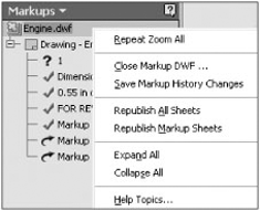
Once you've reviewed all markups, you can save the markups back to the DWF or DWFx file. You can choose to republish only the sheets that are marked up or republish all sheets. You can access these commands by right-clicking the DWF or DWFx filename in the Markups browser, as shown in Figure 14.34.
- Import and export geometry
In the design world today, you most likely need to transfer files to or from a customer or vendor from time to time. Chances are, the files will need to be translated to or from a neutral file format to be read by different CAD packages.
- Master It
You are collaborating with another design office that does not use Inventor. You are asked which you would prefer, IGES or STEP files.
- Use Inventor file translators
Inventor offers native file translators for CATIA, Pro/ENGINEER, SolidWorks, Unigraphics, and other CAD file types. This allows you to access these file formats with Inventor and translate the files into Inventor files directly.
- Master It
You are a "job shop" and in the past have been required to maintain a copy of SolidWorks in addition to your copy of Inventor in order to work with customers who send you SolidWorks files. You would like to eliminate the cost of maintaining two software packages.
- Work with imported data
Using the construction environment in Inventor, you can repair poorly translated surface files. Often a file fails to translate into a solid because of just a few translation errors in the part. Repairing or patching the surfaces and promoting the file to a solid allows you to use the file more effectively.
- Master It
You download an IGES file from a vendor website, but when you attempt to use the component in your design, the surface data is found to have issues.
- Work with Design Review markups
Design Review offers you and the people you collaborate with an easy-to-use electronic markup tool that can be round-tripped from Inventor. Design Review markups can be made on both 2D and 3D files.
- Master It
You want to use Design Review to communicate with vendors and clients in order to save time and resources, but you have found that others are unsure of what Design Review is and how to get it.