
Frame Generator consists of several tools that automate frame modeling. You can select lines, edges, and points to specify the location of members. Frame Generator derives the selections into a part. This part is called a skeleton because it provides the framework for the members. The skeleton part automatically updates when a change is made to the original geometry, which updates the frame member size or position.
Frame Generator gets structural profiles from the Content Center. In addition to the structural profiles included in the Inventor libraries, you can author and publish your own profiles. This is useful for adding profiles of extruded aluminum, plastic, and other materials, since the structural profiles in the Inventor libraries are standard steel shapes.
In this chapter, you'll learn to:
Work with frame files
Insert frame members onto a skeleton model
Add end treatments to frame members
Make changes to frames
Author and publish structural profiles
Create BOMs for Frame Generator assemblies
The Frame Generator panel, shown in Figure 15.1, is on the Design tab of the assembly ribbon. It has tools specific to Frame Generator plus the Beam and Column calculator from the Design Accelerators.
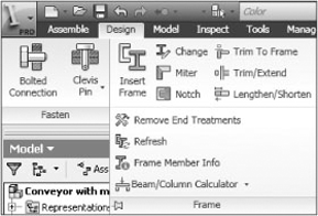
The tools fall into four categories: working with frame members, creating end treatments, doing maintenance, and performing analysis. Insert and Change are used to place and replace frame members. Miter, Trim To Frame, Trim–Extend To Face, Notch, Lengthen–Shorten Frame Member, and Remove End Treatments are used to add end treatments to frame members. Frame Member Info and Refresh are maintenance tools. Beam And Column is an analysis tool for frame members.
When you create the first members in a frame assembly, a dialog box prompts you for filenames. Frame Generator creates a subassembly and a skeleton file in the parent assembly. The subassembly does several things. It acts as a container for the skeleton and frame member, isolating them from the assembly solver, and it acts as a filter so Frame Generator tools, such as Frame Member Info, ignore other assembly components. Each frame member is created as a separate file.
Special attributes in the frame subassembly contain references to the parent assembly. This enables the frame skeleton to maintain references to the other assembly components. One limitation is that you can't use copies of the frame generated with the assembly Copy tool in other assemblies and maintain Frame Generator functionality.
Frame Generator initially creates frame members the same length as the selected geometry. When you add end treatments, the length is adjusted to make the member longer or shorter. To accomplish this, the structural profiles are created with a From-To extrusion between two work planes, as shown in Figure 15.2.

When the part is first created, the start plane is coincident with the XY plane, and the end plane is set to the initial length. When an end treatment is added, the start or end plane is moved to shorten or lengthen the member.
The parameter relationships that control the length are complex. Three parameters drive the length, two parameters are driven by those parameters to determine the length, a reference parameter reports the overall length, and a parameter is used in the BOM, as indicated in Figure 15.3.
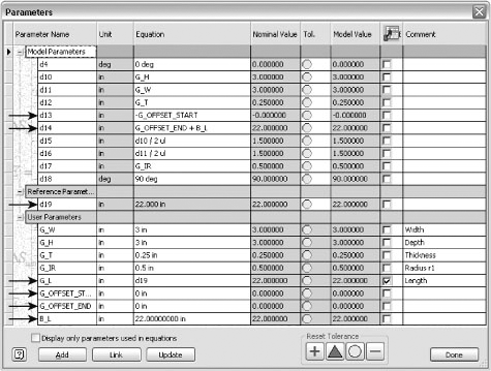
Table 15.1 lists the length parameters.
Table 15.1. Frame Member Parameters
Parameter | Description |
|---|---|
B_L | The initial length of the member. |
G_OFFSET_START | The offset value of the start work plane. |
G_OFFSET_END | The offset value of the end work plane. |
d13 | The parameter for the start work plane. It is driven by G_OFFSET_START. |
d14 | The parameter for the end work plane. It is driven by G_OFFSET_END. |
d19 | A reference dimension that measures the overall length of the part. |
G_L | The length parameter that is used in the BOM. It is equal to the reference dimension. |
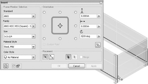
The process for inserting frame members can be broken down into three basic steps. You select the frame member from the Content Center, select the placement geometry for placing the frame members, and adjust the orientation of the frame members.
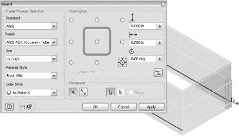
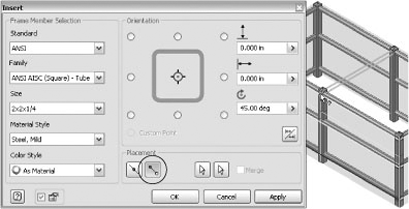
The left side of the Insert dialog box, shown in Figure 15.4, has a series of drop-down fields for specifying the structural shape.

You use the Standard, Family, and Size fields to select the member from the Content Center. These fields are progressive, and the update behavior varies. If you select a new standard, the first family is automatically selected. If you select a new family, the size is not automatically selected.
After you have selected the placement geometry, you can change the position and orientation of the member. A thumbnail of the profile is displayed in a grid of radio buttons that control the position of the member, as shown in Figure 15.5. These positions are based on the rectangular bounds of the profile. As a result, the corner positions of a 1″ by 1″ square tube are the same as a 1″ diameter pipe.
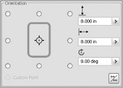
If a custom profile has been authored with an alternate base point, the Custom Point control is enabled. This adds another insertion point to the nine standard ones. The custom point is not displayed in the thumbnail image, so you should confirm the preview is in the expected position relative to the selected edge.
You can fine-tune the position by entering values in the horizontal and vertical fields. You can also rotate the member. For example, food processing equipment frequently has horizontal members rotated 45 degrees so spilled food doesn't build up on top of square tubing.
The Mirror Frame Member button is used for profiles that don't have rotational symmetry, such as C-channel and angle iron.
The orientation changes affect all the members of a select set. Depending on the geometry, it might be more efficient to use a batch select tool and change the orientation of a few members afterward, or you might want to select only those members that have a similar orientation.
Since structural shapes are extruded, Frame Generator needs a method for determining the extrude direction. When an edge is selected, Frame Generator uses the closest endpoint as the start of the extrusion. Depending on where you select an edge, the same radio button can cause the member to be in a different position. The thumbnail is the view of the profile looking at the XY plane. It takes some practice to get a good feel for the relationship between how an edge is selected and the behavior of the radio buttons. Once you understand this relationship, you will be able to predict the behavior and use it to increase your productivity.
To see how this is accomplished, open the file named mi_15a_001.iam from the Chapter 15 directory of the Mastering Inventor 2010 folder. You can use this file to explore the options in the coming pages. When placing frame members, you first specify the Standard, Family, Size, and Material Style settings, as shown in the dialog box in Figure 15.6. Click the first edge near the bottom and select the corner radio button to place the member inside the surface, as in this figure.
Click the next edge near the bottom, as shown in Figure 15.7, and its relative position is the same as the first member. This places the member outside the surface.
The second member needs to be inside the surface, so deselect it by holding the Ctrl key and clicking it. Then reselect the edge near the top, as shown in Figure 15.8. This time, since the extrusion direction was reversed, the member is inside the surface.

When using a custom profile with an alternate insertion point defined, the Custom Point control is enabled. This point is in addition to the standard insertion points around the profile. Figure 15.9 shows a profile with an alternate insertion point.
When you select placement geometry, you can select edges and lines, or you can select two endpoints. When you select edges and lines, you can insert multiple members. When you select two endpoints, you can place only one member at a time. The most common placement method is by selecting lines and edges. This allows the most flexibility in geometry selection and the use of batch select tools.
There are two philosophies for placing frame members. Some people like to place frame members individually, making sure each one is in the correct position and orientation. Other people like to place as many members as possible and then edit them as necessary. The method you choose will depend on the type of models you work with, how much effort you put into setting up the skeleton models, and, most important, the way you like to work.
Frame Generator has several tools for selecting geometry. Multi Select is the default selection mode. These are the standard tools for building a selection set: picking, using selection windows, and using the Shift and Ctrl keys to add and subtract. Two additional select modes are available in the context menu shown in Figure 15.10: Chain Select and Sketch Select.
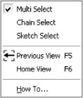
Chain Select automatically selects all lines and edges that are tangentially connected to the selection. Chain Select will not follow past a point that has multiple lines or edges, even if one of them is tangential.
Sketch Select selects all the lines in a sketch. You can select the sketch in the browser or click a line in the graphics window.
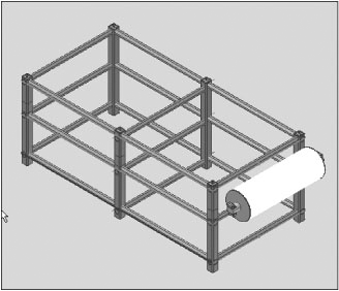
The default selection mode is Insert Members On Edges. You can select any combination of sketch lines and model edges and surface edges. Figure 15.11 shows conveyor model mi_15a_001.iam. The frame skeleton is constructed of surfaces and sketch lines. The power roller is in the correct position, but it needs support members.
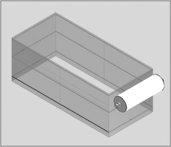
Figure 15.12 shows the conveyor frame populated with ANSI AISC HSS (square) tubing. The legs are 3 × 3 × ¼ square tubing positioned inside the surface. On one side, the legs have a removable section for installing the belt. The legs can be inserted in pairs by using the edge selection technique demonstrated in the "Changing the Orientation" section earlier in this chapter.
The horizontal members are 2 × 2 × ¼ square tubing inserted at 45 degrees. Switch to Sketch Select to select all of the geometry in a sketch at once (see Figure 15.13). After these tubes are inserted, you can turn off the visibility of the conveyor frame skeleton part to reduce clutter by right-clicking it in the browser.

The power roller supports are 1½ × 1½ × 3⅙ square tube. The lower support is flush with the flat, and there is a small gap between the upper support and flat. Select the edge of the lower flat, and offset the tube horizontally to align it with the leg. Select the edge of the upper flat and offset it horizontally to align with the lower support and 0.125″ vertically, as shown in Figure 15.14.

In some cases, it can be more productive to select the endpoints rather than create the geometry. The select set is limited to two points, but you can speed up the insertion process by selecting Apply from the context menu and then picking the next pair of points.
In this example, the conveyor frame needs horizontal members in the center. The conveyor frame skeleton is turned back on. Change the placement method to Insert Members Between Points in the Insert dialog box. Pick the endpoints of the side lines in each sketch, as shown in Figure 15.15, to place the 2 × 2 × ¼ square tube.
Frame Generator follows two rules to give a frame member its initial orientation. If it is the first member in a select set, the member is aligned to adjacent geometry or the coordinate system. For the rest of the select set, Frame Generator tries to align the members to the first selection. These rules work well for most rectangular machine frames. If part of the frame is at an angle and there isn't a good reference, Frame Generator can select an orientation that doesn't match the design intent.
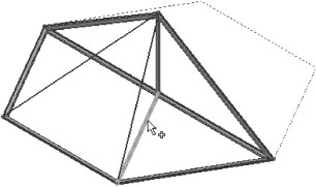
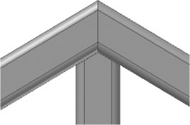
The frame in Figure 15.16 is the roof for a sunroom. The members for the base and back have already been inserted, and the two angled rafters need to be inserted. When you insert a member on the left line, the orientation is skewed, as shown in Figure 15.17.
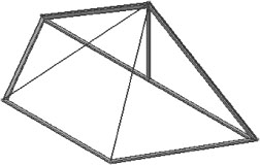
On the right side, a reference line was added to the base. If that line is selected before the left line, as shown in Figure 15.18, Frame Generator can align the angled member. Since a frame member isn't needed on the bottom line, it can be deselected, and the angled member is inserted correctly, as shown in Figure 15.19.
Using reference geometry for angled frame members is an art. If you regularly create these types of frames, you will develop a feeling for the ways that Frame Generator aligns members, and you will learn when and how you need to add references.
The end treatments are some of the most powerful Frame Generator tools. As you add end treatments, the frame member length automatically updates. The end treatments also carry over if you change the frame member to a different profile.
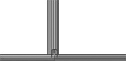
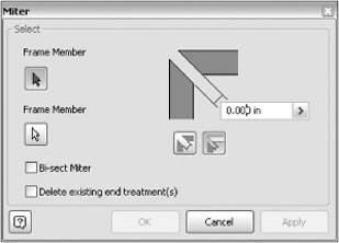
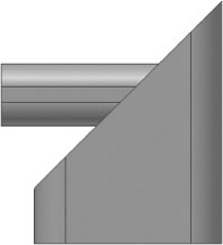
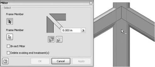
The Miter end treatment makes angle cuts on two members. Figure 15.20 shows the Miter dialog box. You can miter multiple members by applying the end treatment to each pair of members.
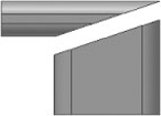
The default selections cut along an angle resulting in full-face contact between the members as shown in Figure 15.21. Bi-sect Miter splits the angle between the members. Figure 15.22 shows the cut is located where the centers of the two members intersect.
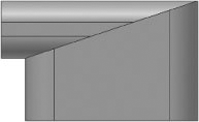
You can add a gap between the members. The default gap is split between the two members. If you want to have the end gap on one member, as shown in Figure 15.23, it will be removed from the first selection.
The sunroom frame, named mi_15a_007.iam, has a miter end treatment between the two angled members on the back, and the vertical member needs to be mitered to fit, with a small gap to allow for manufacturing tolerances.
Figure 15.24 shows the first step to create the miter. The gap should be cut only on the vertical member, so it needs to be the first selection.
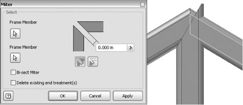
The vertical member still needs a miter to trim the other side, so the miter is repeated with the same settings, as shown in Figure 15.25.
The resulting miter shown in Figure 15.26 requires two cuts on each member. An alternate method that produces a more cost-effective joint will be shown in a later section.
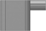
This end treatment trims or extends both members so they are flush. The first selection is made flush to the second selection, and the second selection butts up to the first. Figure 15.27 shows the selections, and Figure 15.28 shows the results.
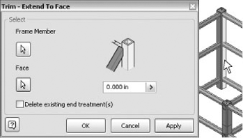
This end treatment is the only one that can trim multiple members at once. You select the members you want to trim, and then you select the cutting face. A separate end treatment feature is created for each frame member. If you edit or delete the end treatment for a particular member, it does not affect the other members.
Returning to the conveyor example, the conveyor frame is a typical machine frame. All of the members are perpendicular with simple butt joints. Since you can select multiple members, as shown in Figure 15.29, using Trim and Extend is an efficient way to add details. Since the frame is symmetrical, you can trim the members on both sides at once. If a design change requires an offset leg, it is pretty straightforward to edit the end treatments on the members and change the face selection.
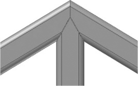
This end treatment can also be used to create miters. Applying miter end treatments to the sunroom frame resulted in a complex joint. Trimming the vertical member to fit the angled members results in the less expensive detail shown in Figure 15.30.
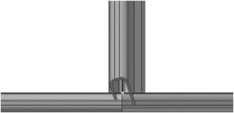
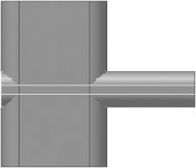
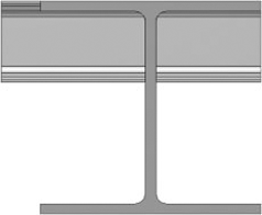
Notch cuts one frame member to match the other. It uses the profile to create a cutting surface. You can't create an offset, so the cut is an exact match. This is simply a cut operation, so the frame member is not shortened or extended before the cut. If you notch the short I-beam shown in Figure 15.31, which extends past the tall I-beam, the extra lump will be left as shown in Figure 15.32. If the members don't intersect, the notch will have little or no effect.

A notch is frequently a secondary end treatment. For example, if you add a Trim/Extend To Face end treatment first, the notch will remove any intersecting material.
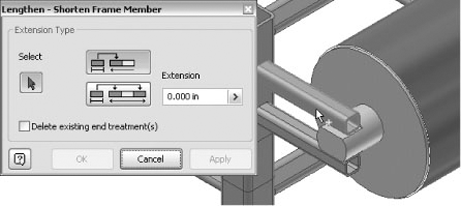
Sometimes, there isn't another frame member you can use as a reference for an end treatment. For example, the power roller supports on the conveyor are stubs that were placed by selecting the part edges. The power roller is moved to adjust the belt tension, so the tubes need to be extended away from the frame.
The tubes were already extended to the frame. Since the total length of the tube should be a nominal value, measure the length of the tube before starting the command. In this case, the tube is 9.088″ long. The tube needs to be about 3″ longer, so the overall length should be 12″. Copy the length from the Measure Distance dialog box, and paste it into the Lengthen–Shorten dialog box to build an expression.
Frame Generator modifies the end closest to the pick point, as shown in Figure 15.33. If the pick is closer to the frame, an error will display because there is already an end treatment at that end. Although it isn't obvious at first, this is an intuitive way to select the member, since you are likely to pick the member close to the end you will modify.
Maintaining existing assemblies can be time-consuming. Frame Generator provides several tools that help streamline this process.
The Remove End Treatments tool removes all end treatments from a frame member. You can also select multiple members for the batch removal of end treatments. This is handy if you need to change the end treatments on a few members or if you have to rebuild a frame.
The Frame Member Information tool is used to query frame members. It displays the family and size information, mass properties, and material. This is a useful tool because it quickly gives you information about a member. For example, it can tell you the wall thickness of a tube. Since the tool filters for frame members, you can use it at any level of the assembly.
The Refresh tool is a Content Center tool. It checks the Content Center for the latest revision of the members in the frame. If a newer version is available, it will prompt you to replace it. End treatments are retained during refresh, but other features, such as holes, are not carried over to the new member.
Like other Design Accelerator dialog boxes, the message pane at the bottom and the calculation results pane on the right side can be opened and closed by clicking the chevrons. You can drag the splitter bar to resize the panes or double-click it to open or close them.
When you click OK, a component is added to the assembly that contains all the data and results.
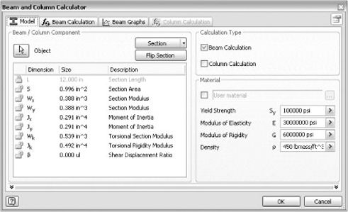
Referring to the conveyor assembly again, the Beam And Column Calculator might be used to calculate the loading on the power roller supports. When the tube is selected the calculator automatically loads the section properties from the Content Center, as shown in Figure 15.34. Although the Content Center has most of the section properties, be aware that some data is missing. You can use several methods for determining the properties.
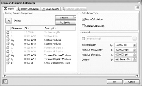
Figure 15.34. The section properties for the power roller support are loaded from the Content Center.
Inventor has a tool to calculate the properties of a closed sketch profile. If you want to use this tool for the section properties of a frame member, you can open the frame member, place a sketch on one end, and project the face. Once you have the profile, select Tools
The regional properties are calculated with respect to the sketch origin. Depending on the profile, you may have to edit the sketch coordinate system to locate the sketch origin at the center of the profile.
Another option for calculating section properties is to use the Section button in the Beam And Column Calculator. When you click the button, a list of geometric shapes displays. When you select a shape, a dialog box like Figure 15.35 displays for entering dimensions. The calculated properties assume sharp corners and constant thickness, so the results won't be accurate for profiles with tapered flanges.
Flip Section is used to change the orientation of the x- and y-axes. The z-axis is always in the direction of the extrusion. Gravity is always in the negative y-axis direction, so it is important to make sure the calculation coordinates match the assembly coordinates. If the beam is at an angle, you have a couple of options for handling gravity. You can place a copy of the beam horizontally in the assembly. If you want to ignore the effect of gravity, there is an option on the Beam Calculation tab to turn the gravity load off.
Both beam and column calculations are available. The beam calculations focus on deflection based on loads and supports. The Column calculation checks for buckling. You can select Beam, Column, or both calculation types. The Calculation tabs are turned on and off based on the selections.
The default material properties do not correspond to an actual material. They give you an example of the required properties. You can enter properties for a particular material, or you can select a generic material. When you check the box, a dialog box displays with materials such as gray cast iron, steel, and aluminum. These properties can be used for initial calculations, but for more accurate results, you should enter the properties for the particular alloy you are using.
The following steps use the power roller supports found in the file named mi_15a_014.iam. Follow these steps to enter the member data into the dialog box:
Select one of the lower supports for the power roller.
If necessary, click the padlock (unlocking it) for Section Length, and change the value to 12″.
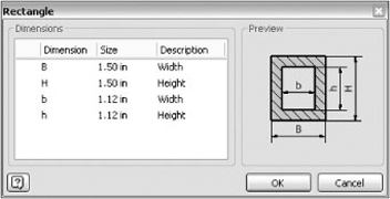
Click Section, and select Rectangle.
Enter the tubing dimensions (1.5″ outside and 1.12″), and click OK.
Select both the Beam and Column calculations in the Calculation Type group.
Click the check box next to the Material field to launch the Material Types dialog box. Select Steel, and click OK.
The coordinate system alignment is correct for this example. In this case, gravity could be ignored, but having the correct orientation simplifies adding the loads and interpreting the results.
The dialog box should look like Figure 15.36. Note that all the section properties except Shear Displacement Ratio are calculated. This property is optional for the calculations. Comparing the calculated values with the original ones, Section Area and Moments Of Inertia are close but higher.
The Beam Calculation tab, shown in Figure 15.37, has the controls for defining the loads and supports for beams and columns, as well as calculation options. The Engineer's Handbook (available from the Design Accelerator panel bar or the Help system) contains the equations used in the calculations. You should review those equations before you use this calculator.
The Loads & Supports group contains a browser and controls for adding and removing loads and supports for the frame member. All of the controls are located at the top of the group or on the context menu in the browser.
The drop-down menu switches the browser between loads and supports views. The controls, as shown in Tables 15.2 and 15.3, change with the current browser view.
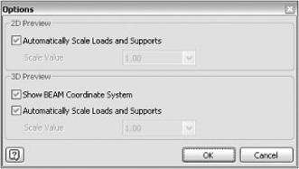
The Options dialog box shown in Figure 15.38 gives access to visibility controls for the 2D and 3D previews. By default, the size of the loads and supports dynamically update to maintain the same size as the view scale changes. You can turn off the automatic update and set a static scale value. The Options dialog box is the same whether it is launched from the loads or supports controls.
Each load or support can be edited in the browser by double-clicking or by clicking the ... button. A properties dialog box displays that has controls for specifying the location, size, and direction of the force.
The Calculation Properties group, as shown in Figure 15.39, has four controls. The controls adjust how the calculations are made.
The Use Density check box adds gravity as a load. This is selected by default.
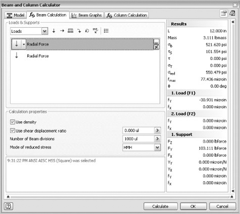
Table 15.2. Loads Buttons
Button | Description |
|---|---|
Adds a force. | |
Adds an axial force. | |
Adds a distributed force. | |
Adds a bending moment—a single twisting force perpendicular to the z-axis. | |
Adds a torque load—a twisting force around the z-axis. Two equal and opposite torque loads are required. | |
Adds a combined load—any of the forces added at the same point on the beam. |
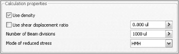
The Shear Displacement Ratio check box is used when calculating the twist angle caused by torsional loads. The value is determined by the profile shape. It is also called the form factor of shear. Textbooks contain formulas for calculating this number. This check box is selected by default.
The default setting for Number Of Beam Divisions is 1000. Increasing the number of divisions can result in improved accuracy for longer beams. You should experiment with different values to see whether the number of divisions causes a significant change in the results.
Mode Of Reduced Stress has two options for modeling the stress distribution. The Huber-Mises-Hencky (HMH) method is based on the maximum-energy-distortion criterion, and the Tresca-Guest method is based on the maximum-shearing-stress criterion. The HMH method is the default selection.
The result pane on the right side updates when you click the Calculate button. Warnings will display in the lower plane if the calculation indicates that stresses are too high.
For the conveyor example, the support is welded to the frame at one end and unsupported at the other. The power roller weighs 150 pounds, and the torque is 40 pound-feet. The torque causes the power roller to twist between the supports. The edge of the flat is 1.5″ from the center of the power roller. This means the reaction force at that point is 320 pounds. Both the weight and the reaction force are split between the two sides.
For the power roller weight, add a 75-pound radial force at 10″ (the maximum distance for the power roller).
For the torque reaction, add a 160-pound radial force at 11.12″.
Switch to the Supports browser.
Delete the Free support.
Click the drop-down arrow for the Fixed support, and select Restraint.
Leave Use Density checked.
Deselect Use Shear Displacement Ratio since you don't have a value for that property.
Click Calculate; the reduced stress is 4126 psi, which is 9.4 percent of the 44000psi yield stress.
The dialog box should look like Figure 15.40. Note that the forces are displayed in the graphics window. If you hover over a force, a tool tip displays the information. You can drag the force to a different position, or you can double-click the force to display the properties dialog box.

The Graph Selection pane allows you to select the results you want to display. The selected graph displays in the bottom of the Graph group. At the top of the Graph group is a schematic of the beam, supports, and loads. You can drag the supports and loads to different positions. If you double-click a support or load, the properties dialog box displays so you can directly edit the data. The Calculate button is not available on the Beam Graphs tab, so you have to switch back to the Beam Calculation tab to update the results.
The Beam Graphs tab is primarily intended for reviewing results. Twenty-two graphs are available on the tab. This example is a pretty simple analysis. You should experiment with other loads (torques and bending moments) and support types and then view the results on the graphs.
The Column Calculator tab checks for column buckling. In the Loads group, you enter the axial load and the factor of safety, and you select a coefficient for the end loading conditions. When you click the ... button, a dialog box displays with four end conditions. If you have different end conditions, you should enter the proper coefficient from a reference book.
You shouldn't have to enter any data in the Column group. The length, section area, and least moment of inertia are carried over from the Model tab. The reduced length value is calculated by multiplying the length by the end coefficient.
For example, let's say that during transport, the frame shifts and the power roller supports slam into the trailer wall. The power roller was removed during shipping, so the supports take all the force from the impact, estimated at 4,000 pounds evenly distributed across the four supports. Set the axial load to 1,000-pound force, and click Calculate to determine whether the supports will buckle. Figure 15.41 shows the results.

Frame Generator is integrated with the Content Center. The authoring and publishing process is similar to that used for other applications. Since Frame Generator requires specific modeling techniques, the authoring process will make some changes to the model and the parameters.
The authoring process for a frame member is similar to component authoring. The Structural Shape Authoring tool, located on the part-modeling panel bar, is used to prepare the part for publishing. The tool identifies the geometry used for placement, sets the parameters, and modifies the part so Frame Generator can use it.
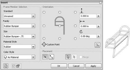
This example uses the file named mi_15a_020.ipt found in the Chapter 15 folder on the book's accompanying DVD. This iPart is a rubber bumper that is attached to frames. There are parameters to control the dimensions, but the engineering properties (moments of inertia and so on) were never calculated. Since this isn't a load-bearing part, these properties aren't required.
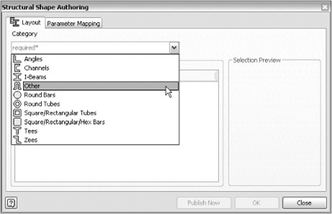
Once the part is open, you can access the Structural Shape Authoring tool by clicking the drop-down on the Manage tab's Author panel. When the authoring tool starts, everything is blank. Once a category is selected, the dialog box will update with the appropriate controls. Since this is an unusual part, select the Other category, as shown in Figure 15.42. Frame Generator looks in the Structural Shapes category only, so you have to select one of the standard categories or create a new one in the Content Center editor. You can't add a category through the authoring tool, so you have to add the category to the Content Center before authoring. See Chapter 7 for more information on Content Center.
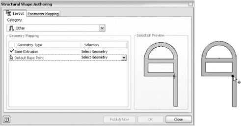
Since there is only one extrusion in the part, the base feature is automatically selected. The default base point is indicated at the center of the profile. For this part, the inside corner of the flanges is the natural insertion point. Click Select Geometry, and select that point in the model, as shown in Figure 15.43.
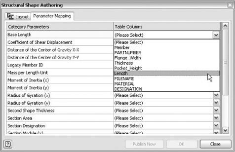
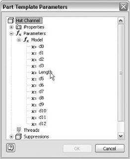
The Parameter Mapping tab has one required field: Base Length. This is the parameter for the extrusion distance. Since this is an iPart, when you click in the field, the iPart properties are listed as shown in Figure 15.44. If this were a regular part, the Part Template Parameters dialog box would display a browser tree, as shown in Figure 15.45. The rest of the parameters are optional. They are mechanical properties of the profile necessary for calculating loads with the Beam And Column Calculator.
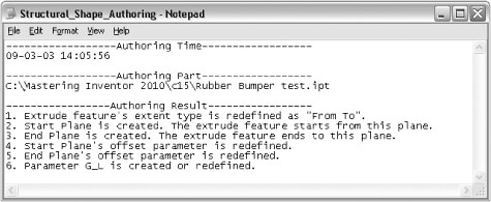
When the geometry and Base Length parameter are mapped, the Publish Now and OK buttons are enabled. Clicking either button will update the part and close the dialog box. Publish Now will also launch the Content Center publishing wizard. When the part is updated, a dialog box displays with information about the changes. A log file, as shown in Figure 15.46, is created in the project directory that lists the changes to the part.
If you inspect the part after authoring, you will see that the browser and parameters have been updated. The details of the model and parameters are discussed in the section "Exploring the Anatomy of a Frame Member," earlier in this chapter.
The publishing process uses the Publish Guide wizard. Since the part was authored, most of the publishing information has already been added to the file. If you aren't familiar with publishing to the Content Center, you should spend some time learning how to work with libraries before you publish a part.
These publishing steps are important for Frame Generator:
When you define the family key columns, the Length parameter must be set as a key column.
In the Family Properties pane, the standard organization is used to categorize the member during insertion. If you leave this field blank, the category selection will be Unknown.
In the thumbnail image pane, a special thumbnail is displayed. Since the thumbnail is used as the orientation image in the dialog boxes, it is important to use the thumbnail Frame Generator creates.
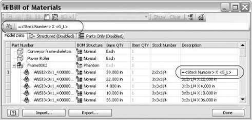
By default Frame Generator parts are set to calculate their base quantity from the length of the part. This differs from standard parts that calculate their base quantity from the number of parts in the assembly. When parts are authored for use in the Frame Generator, the Base Quantity setting is automatically set to the length. To get a part count in the parts list for your assemblies, you will want to configure them to read the item quantity rather than the base quantity. You can use both columns if that fits your needs, or have the BOM display one quantity and the parts list display the other. You can also use the BOM expression builder to create a description built off the Stock Number property and GL parameter (Length). You can use the CUTDETAIL parameters in expressions to show the cut information for each member. Note that you can copy the expression in one cell of the BOM, multiselect the rest of the column, and then right-click and choose Paste to set the expression to all of the parts in the BOM. Figure 15.47 shows the BOM editor listing the base quantity and the item quantity along with an expression being built to fill out the description.
It is a good idea to let Frame Generator name the frame members for you and use the Part Number property to manage the parts, rather than the part name. Once you've set an expression as just described, you can sort the BOM by that column to group the like items, then set one of the part numbers, multiselect the items, and choose Paste from the context menu to set them all the same. If you want the items to be merged, leave the Part Number Merge Settings selected. The Part Number Merge Settings button is in the top right of the BOM editor dialog box.
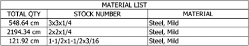
In the drawing environment, use a Parts List style similar to the default Material List style found in the standard templates. This parts list is already configured to group by Stock Number and Material, as well as sum the values of each unique stock number type. Figure 15.48 shows a parts list placed using the Material List style to roll up the lengths.
- Work with frame files
Frame Generator puts all the members at the same level in the assembly.
- Master It
You have a frame that is built up in sections that are welded together. You need to document the manufacturing process.
- Insert frame members onto a skeleton model
Frame Generator builds a skeleton model for the frame from the selected lines and edges.
- Master It
Since Frame Generator builds its own skeleton model, you don't have to build a master model before you start creating the frame. You can use sketches, surfaces, and model edges to insert frame members.
- Add end treatments to frame members
Frame Generator does not support end treatments on merged members.
- Master It
Let's assume you are building a stairway and the handrail has curved sections.
- Make changes to frames
Inventor provides detailed frame member information.
- Master It
You need to determine the size and wall thickness of the tubing and make it either thicker or larger.
- Author and publish structural profiles
Frame Generator uses structural shapes from the Content Center.
- Master It
You need to add custom aluminum extrusions to the Content Center so Frame Generator can access them.
- Create BOMs for Frame Generator assemblies
Frame Generator has special parameters for frame members.
- Master It
You need to add the profile dimensions and the length to the Description field.