
When creating thin wall plastic parts, there are two basic approaches to getting started. One approach is to start with a solid and shell it out; the other is to start with a surface and thicken it. Although these methods approach thin wall features from different start points, the end result can be the same. You can also mix and match the two methods as required in order to achieve your design.
Typically once you've established the base feature, you can add other plastics part features. Inventor has several built-in tools for creating plastic part features when working in the parts modeling environment. You'll find these tools on the Plastic Features panel of the Model tab. Although many of the other tools covered in this chapter, such as Shell and Thicken/Offset, are used to design all types of parts, they are commonly used along with the plastic-specific tools and therefore are covered in this chapter.
In this chapter, you'll learn to:
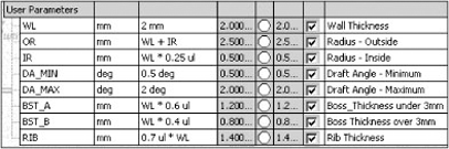
When working with plastic thin wall parts, you should follow certain design parameters throughout the features of the part in order to avoid issues with shrinkage and voids caused by uneven cooling once the part comes out of the mold. To help with this, you may want to create a plastic part template with your design parameters already set up. Figure 19.1 shows an example of the parameters in such a template, with the design rules already set up and ready for use.
You can use the Thicken/Offset feature to add thickness to a surface feature in order to create a thin wall solid. Although you can use this tool to create output surfaces and remove solid material, typically when using Thicken/Offset to create plastic thin wall features, you'll select an existing surface feature to thicken and then set the output type to produce a solid.
To create a thin wall part using the thicken method, follow these steps:
Click Open on the Get Started tab, and browse for the file named
mi_19a_022.iptin the Chapter 19 directory of the Mastering Inventor 2010 folder and open it.On the Model tab, select the Revolve tool, and notice that Output defaults to Surface because the sketch is an open profile.
For the Profile selection, click any solid line in the sketch.
For the axis, select the dashed centerline.
Leave the extents solution set to Full, and click OK.
Next select the Thicken/Offset tool on the Surface panel of the Model tab.
Switch the select mode from Face to Quilt, and then select any face on the revolved surface.
Set the distance input to 2mm, and change the direction arrow so that the thickened material is placed to the inside of the part.
Ensure the output is set to Solid, and then click OK.
Notice the sharp edges. Although you could use the Fillet tool to select all the outside edges of the solid and then attempt to set fillets to all the inside edges of the solid, there is an easier way. If you place the fillets on the surface, then the thickened solid feature will follow the shape and include the fillets. To do this, continue with these steps.
From the browser, select the end-of-part (EOP) marker, and drag it above the thicken feature.
Select the Fillet tool on the Modify panel, and set the radius to 8mm.
Set Select Mode to Feature, and then select the revolved surface.
When you see a preview of three fillet edges, click OK.
Next drag the EOP marker down below the fillet feature in the browser, and you'll note the thickened solid now includes the filleted edges.
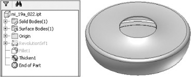
Lastly, right-click the revolution feature in the browser, and toggle the visibility off. Figure 19.2 shows the revolved and thickened part.
Another approach to creating thin wall feature and parts is to create a solid and then use the Shell tool to hollow it out. When creating a shell feature, you set the wall thickness and select the faces you want to remove. Material from the interior of the part is removed, resulting in a cavity. To create a thin wall part using the shell method, open the file named mi_19a_024.ipt in the Chapter 19 directory of the Mastering Inventor 2010 folder, and then follow these steps:
On the Model tab, select the Revolve tool, and notice that Output defaults to Solid because the sketch is closed. The profile and axis selections will automatically select, because there is only one possible solution for each.
Leave the extents solution set to Full, and click OK.
Next click the Shell button on the Modify panel of the Model tab.
Select the circular face on the top of the revolution feature as the Remove Faces selection.
Ensure the direction is set to Inside, set the thickness to 2mm, and then click OK.
Notice the odd result at the opening of the part. You will fix this by creating a boundary patch surface and then using the Thicken/Offset tool to recut the hole. You'll also place some fillets on the sharp outside edges.
Click the larger diameter edge of the center hole for the BoundaryLoop selection, and click OK. This creates a surface feature you'll use to recut the hole.
Select the Thicken/Offset tool on the Surface panel, and click the boundary patch's surface.
Set Solution to Cut, set Distance to 2mm, and set the direction to go down into the part.
Ensure the output is set to Solid, and then click OK.
Select the Fillet tool on the Modify panel, and set the radius to 8mm.
Select the three outside edges—two along the bottom and one along the top. Be certain these are the outside edges and not the inside edges; then click OK.
Next drag the fillet feature above the shell feature in the browser. This will allow the shell to follow the outside fillets and translate them to the inside edges. If you cannot drag the fillet above the shell feature, mostly likely you have inadvertently selected an inside edge. If so, the fillet cannot exist before the shell because it is dependent upon the edge created by the shell.
Lastly, right-click the boundary patch feature in the browser, and toggle the visibility off. Figure 19.3 shows the revolved and shelled part.
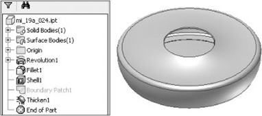
If you were to compare the parts created by the Thicken/Offset method and the Shell method, you would find that the two are not quite identical. The difference is in the opening cutout. In the shelled version, a boundary patch was used to recut the opening down into the part (along the y-axis). In the thickened version, the opening was left in its natural condition. You could use the Boundary Patch tool to clean up the opening in that case as well.
Often when designing plastic parts, it is useful to create mating parts within the same file. To do this, you can use the Split tool to divide a single body into two mating bodies. You can also use the Split tool to split the surfaces on a solid so that they can be manipulated individually. To see how the Split tool is used, open the file named mi_19a_026.ipt in the Chapter 19 directory of the Mastering Inventor 2010 folder, and then follow these steps:
Expand the Solid Bodies folder in the browser, and notice there is currently only a single solid listed in the folder. You will use the Split tool to divide this into two separate solids.
On the Model tab's Modify panel, select the Split tool.
For the Split Tool selection, click the sketch profile running through the part.
For the method, click Split Solid button (third from the top), which will split the existing part into two separate solids.
Click OK, and notice Solid1 has been replaced with two new solids in the Solid Bodies folder.
To work with just the top solid, select it in the Solid Bodies folder of the browser, right-click, and choose Hide Others.
Next you'll create a 3D sketch to split the surface of the solid. Use the Sketch drop-down on the Model tab, and select 3D Sketch.
On the 3D Sketch tab, select the Silhouette Curve tool, choose the solid as the Body selection and the visible y-axis as the Direction selection, and then click OK.
This creates a sketch curve along the face where a beam of light shining down from above would create a shadow. Click Finish Sketch to exit the 3D sketch.
Select the Split tool again, and choose the 3D Sketch curve for the Split tool selection.
For the Face selection, choose the face that the 3D Sketch curve is encircling. Ensure the Faces option is set to Select and not All. This will split just the outside face of the part, whereas All would split both the outside and inside faces. Click OK.
Now select the Thicken/Offset tool, choose the bottom half of the face you just split, and set the Distance to 1mm.
Ensure Output is set to Solid, Solution is set to Join, and Direction is thickening out from the part; then click OK.
Next right-click the thicken part you just created in the browser, and choose Properties.
Set Feature Color Style to Blue, and click OK.
Right-click the solid in the Solid Bodies folder, and choose Properties. Enter Cover for the name. Click the Update button to set see the general properties of this solid. You'll notice also that you can set the color for the entire solid body here. Selecting the Strip Overrides check box would reset the blue thicken feature to abide by the color of the entire solid. Feel free to choose a color of your liking, and then click OK.
Finally, right-click the solid in the Solid Bodies folder, and choose Show All to turn the visibility of the other solid back on.
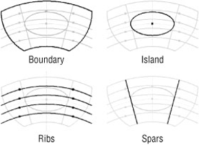
You can use the Grill tool to create vents and openings on the thin wall parts to provide access and airflow to parts housed within an exterior part. To create grill features, use the Grill tool to project 2D sketches on the surface of the part to create various raised or recessed features. Although the boundary sketch is the only required grill element, you can create islands, ribs, and spars and then give them all a draft angle. You can also check the flow area of the opening to ensure it meets the required area. Open the file called mi_19a_028.ipt in the Chapter 19 directory of the Mastering Inventor 2010 folder, and then follow these steps to create a grill feature:
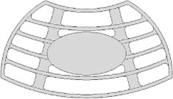
Select the Grill tool from the Plastic Part panel of the Model tab. You'll see a sketch with all the various elements of what will become the grill within it. Figure 19.4 shows the sketch elements separated out into the grill elements.
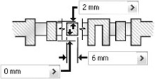
For the Boundary profile, select the outer profile of the sketch as identified in Figure 19.4. Set Thickness to 2mm, Height to 6mm, and Outside Height to 2mm, as shown in Figure 19.5.
Next click the Island tab, and select the elliptical profile of the sketch as identified in Figure 19.4. Leave Thickness set to 0mm so that the island is a solid fill.
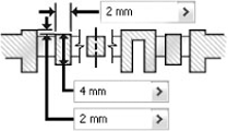
Next click the Rib tab, and select the four arcs identified as the ribs in Figure 19.4. Set Thickness to 2mm, Height to 4mm, and Top Offset to 2mm, as shown in Figure 19.6.
Next click the Spar tab, and select the two lines identified as the spars in Figure 19.4. Set Top Offset to 2mm, Thickness to 6mm, and Bottom Offset to 0mm, as shown in Figure 19.7.
Click the >> button at the bottom of the dialog box, and note the Flow Area setting; then click OK to create the grill feature.
Next you'll pattern the grill feature around the parts. Click the Circular Pattern tool (located next to the Work Features tools).
Select the grill feature for the Features selection, and then click the visible y-axis for the Rotation Axis selection.
Enter 3 for Occurrence Count and 90deg for Occurrence Angle.
Click the Midplane button to set an occurrence on each side of the original, and then click the >> button.
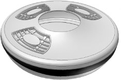
In the Positioning Method area, select Incremental to set the spacing of the grills at 90 degrees each, and then click OK. Figure 19.8 shows the patterned grill features.

With rule fillets, you can create fillets based on a list of rules you've set up in order to determine which edges to fillet. This approach can be a powerful time-saver when working with plastic parts, because it allows you to create many fillets all at once without having to select each and every edge. When a part feature is changed with significance to the rule-based fillets, the rule is evaluated to determine whether it still applies. If so, then the fillets are regenerated for new edges that fit the rule and discarded for edges that do not. Although the Rule Fillet tool is categorized as a plastic feature tool, you can use rule-based fillets for any part you design.
Open the file called mi_19a_030.ipt in the Chapter 19 directory of the Mastering Inventor 2010 folder, and then follow these steps to create a rule fillet feature:
Expand the Solid Bodies folder in the browser, right-click the solid named Cover, and choose Hide Others.
Select the Rule Fillet tool on the Plastic Part panel.
Click the drop-down under the Source column, and select Face.
Rotate the part around, and select the underside face of the grill features (they've each been colored yellow for easy identification).
Set the radius to 2mm, and then set the drop-down in the Rule column to Incident Edges.
In the Options area, deselect the All Rounds check box, leaving All Fillets selected.
In the Incident Edges area, select the visible y-axis as the Direction selection, and then click OK to create all the previewed fillets. Figure 19.9 shows the results of the rule fillet on one of the grill faces.
You'll notice the edges where one of the spars that meets the grill boundary along the top did not receive fillets. This is because they do not qualify according to the rule of incident edges. Although it might seem as if the rule fillet has malfunctioned, close inspection of the grill feature will show there is a gap between the spar and the boundary face. To resolve this, the lines in the grill sketch used for the spars would need to be extended past the boundary edge.
Here is a brief description of the results of the Rule Fillet tool when Faces is selected:
- Incident Edges
Only edges contacting the source faces that are parallel to a selected axis (within a specified tolerance) are filleted.
- All Edges
Edges generated by the selected faces and other faces of the part body are filleted.
- Against Features
Two selection sets are created: a "source" selection and a "scope" selection. Only edges formed by the intersection of the faces in the source with features in the scope selections are filleted.
Here is a brief description of the results of the Rule Fillet tool when Features is selected:
- All Edges
Edges generated by the selected features and the part body are filleted.
- Against Part
Only edges formed by the intersection of the faces of the feature(s) and the faces of the part body are filleted.
- Against Features
Two selection sets are created: a "source" selection and a "scope" selection. Only edges formed by the intersection of the features in the source with features in the scope selections are filleted.
- Free Edges
Only edges formed by faces of the selected feature are filleted.
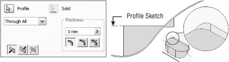
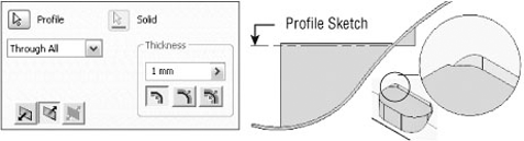
A rest feature is a shelf or landing area applied to a curved or slanted face of a plastic part, often used as a surface on which to mount other components. The results of the rest feature are largely dependent upon the orientation of the rest sketch in relation to the target body and the combination of settings and selections you choose. The Through All option will extend the rest profile through the extents of the target body. The direction arrow will change the results, as shown in the comparison of Figure 19.10 and Figure 19.11.
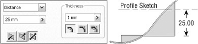
Additionally, you can set a Distance extent. Figure 19.12 shows a rest created 25mm off the profile sketch in both directions.
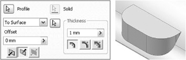
You can also set the rest to terminate using a selected surface. Figure 19.13 shows a rest set to use the target body surface as a termination, with the direction set to go up from the sketch. Notice the result adds material but does not create a pocket.
You can use the More tab in the Rest dialog box to set the Landing options such as taper angles and termination settings. Open the file called mi_19a_032.ipt in the Chapter 19 directory of the Mastering Inventor 2010 folder, and then follow these steps to create a rest feature:
Expand the Solid Bodies folder in the browser, right-click the solid named Cover, and choose Hide Others.
On the Plastic Part panel, select the Rest tool. Because only one profile is available in the visible sketch, it is selected automatically.
Set the direction arrow to point up (use the flip arrow on the left).
Set the thickness to 2mm, and set the thickness direction to Outside.
Click the More tab, set the Landing Options drop-down to To Surface, and then select the visible surface. Set the landing taper to 12 deg, and then click OK.
Turn the visibility of the landing surface off, and inspect the results. You'll notice that the surface contours are translated to the tapered faces. If this is not the result you want, you can use the Delete Face option to clean up the contours.
Select the Heal check box. Then select the four contoured faces, as shown in Figure 19.14, and click OK.
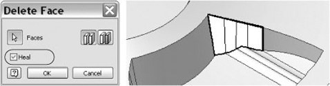
The Delete Face tool is a good way to clean up geometry when needed, but it should not be used indiscriminately because it may create unpredictable results during feature edits. If you have the option to edit an existing sketch or feature in order to get the same result as using the Delete Face tool, then that is typically the best practice. Also, it is a good idea to create small selections sets to delete multiple faces rather than trying to delete them all at once. For example, in this design you would need to delete the contours on the sides of the rest feature on all the inside and outside faces in order to remove the contours completely. This would be best to do as several different features created with the Delete Face tool.
To hold plastic parts together without risking damage to the thin wall features, Boss features are often used to provide a more rigid connection point than just a simple hole. You can use the Boss tool in Inventor to create matched pairs of bosses on mating parts. The half accepting the fastener is the head, and the other half is the thread. You can create both types of bosses using the Boss tool. When required, you can add strength ribs so that the boss features will not be snapped off under load. As a rule, you should consider adding ribs any time the length of the boss exceeds the diameter by more than three times.
Open the file called mi_19a_034.ipt in the Chapter 19 directory of the Mastering Inventor 2010 folder, and then follow these steps to create boss features:
Expand the Solid Bodies folder in the browser, right-click the solid named Base, and choose Hide Others.
Because the Base part has an uneven edge, the boss features to be created will be different heights. To locate the bosses, you will first create work points. Select the Point tool on the Work Features panel.
To create the work point, select the edge of Work Plane4, and then select the inside edge of the base near the intersection of the work plane and the edge.
Repeat this for Work Plane5 and the inside edge of the part. You'll note the work points are placed at different heights from the bottom of the base part. Figure 19.15 shows the resulting work point.
Next you will create grounded work points to establish the inset location for the boss features. Use the drop-down on the Work Features panel to select the Grounded Point tool.
Select the first work point you created at the intersection of the part edge and Work Plane4. You will see the 3D Move/Rotate dialog box, and the triad will appear at the work point location.
Click the Redefine Alignment or Position button in the dialog box.
Next select the small plane on the triad running between the green y-axis and the red x-axis. Then select the edge of Work Plane4. The triad will realign to the work plane.
Now you are ready to place the grounded work point. To do so, first click the red cone shape (arrowhead) of the triad for the x-axis. This will isolate x-axis input in the dialog box. Enter 15mm, and click Apply. This will create a grounded work point.
Next click the Redefine Alignment or Position button in order to redefine the triad location. Click the black ball at the center of the triad first, and then select the work point at the intersection of the Work Plane5 and the inside edge of the part.
Click the blue cone shape (arrowhead) of the triad for the z-axis. This will isolate z-axis input in the dialog box. Enter −15mm, and click Apply. This will create a second grounded work point.
Now you are ready to create the boss features. Select the Boss tool on the Plastic Part panel.
Ensure the Placement drop-down is set to On Point, and then select the two grounded work points for the Centers selection. Click the visible y-axis for the Direction selection, and ensure the preview shows the bosses extending down toward the part base. If they do not, use the Flip arrow to change the direction.
Next click the Head tab. Note the buttons on the left of the dialog box. If you click the lower one, the Head tab becomes the Thread tab, allowing you to place a different boss type. Click the (+) plus button next to the Draft Options area to view the draft inputs available. You can leave the inputs at the defaults.
Next click the Ribs tab, and select the Stiffening Ribs check box to set these options active. Enter 4 in the Number Of Stiffening Ribs input box.
Enter 6mm for the Shoulder Radius input, and then click the (+) plus button next to the Fillet Options area to view the fillet inputs available. Leave the inputs at the defaults.
Click the Start Direction button at the bottom of the dialog box, and then select either Work Plane4 or Work Plane5 to establish the direction. (You can also just enter 45 degrees into the angle input in this particular case.)
Next, click OK to create the boss features. You'll notice each is created at a different height.
Finally, use the Mirror tool to mirror the boss feature, using the YZ origin plane as the mirror plane. Figure 19.16 shows the completed bosses.
Now that the Base half of this design has the head boss features completed, you can create the sketch or work points at the centers of each boss and then use those points to create the thread bosses in the cover.
Lip and groove features are used to mate two parts together so that they fit together precisely. You can use the Lip tool in Inventor to create either the lip or the groove of the part by specifying a path consisting of a set of tangent, continuous boundary edges. You can also use work planes to establish a path extents where a lip is not needed around an entire edge. Open the file called mi_19a_036.ipt in the Chapter 19 folder of the Mastering Inventor 2010 directory, and then follow these steps to create lip features:
Expand the Solid Bodies folder in the browser, right-click the solid named Base, and choose Hide Others.
Select the Lip tool on the Plastic Part panel, and set the type to Lip by clicking the Lip button on the left side of the dialog box.
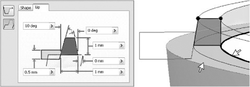
Select the inside edge of the part for the Path Edges selection, and then select the top face for the Guide Face setting.
Next click the Lip tab, set the outside angle to 10 degrees and the clearance to 0.5mm, and then click OK. Figure 19.17 shows the Lip selections.
Next you'll create the groove on the Cover solid. Expand the Solid Bodies folder in the browser, right-click the solid named Cover, and choose Hide Others.
Select the Lip tool, and set the type to Groove by clicking the Groove button on the left side of the dialog box.
Select the inside edge of the part for the Path Edges selection, and then select the center of one of the bosses to establish a pull direction.
Next click the Groove tab, set the outside angle to 10 degrees and the clearance to 0.5mm, and then click OK.
Note that if you did not set a clearance value, you would likely get an error. The Clearance value is useful for creating a planar surface along the path where needed.
Snap fit features are used to secure a plastic part to another part. Although you can model any number of snap fit connections using Inventor's standard modeling tools, Inventor includes a tool to create the common hook-and-loop cantilever snap fit. Figure 19.18 shows a few common snap fits you might create with the Snap Fit tool.
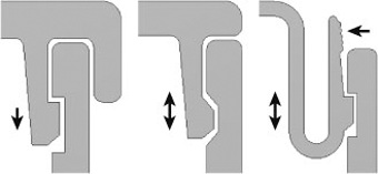
Figure 19.18. From left to right: a permanent locking snap, nonlocking snap, and U-shaped removable locking snap
To insert a snap fit, select an insert point made of either a sketch point or a work point. Open the file called mi_19a_038.ipt in the Chapter 19 directory of the Mastering Inventor 2010 folder, and then follow these steps to create snap fit features:
The first step in creating the snap fit for this part is to bring an existing part into the design using the Derive tool. On the Manage tab, click the Derive button.
Locate and select the file named
mi_19a_099.iptin the Chapter 19 folder, and then click Open.In the Derived Part dialog box, select the first button for the Derive Style to create a single solid-body part with merged seams between planar faces.
Next expand the Solid Bodies folder, and ensure Solid1 is colored yellow, denoting that it is set to be derived into your current design. Expand the Work Geometry folder, set Work Axis1 to be derived as well, and then click OK. You can use the ViewCube to return to the home view.
You'll now use the derived part to subtract material from the Cover part so that it will fit into the opening. Click the Model tab, and then select the Combine tool on the Modify panel.
For the Base selection, select Cover. For the tool body, select the derived part. Set the solution to Cut, click the Keep Toolbody check box, and click OK.
When the tool body component (in this case the derived part) is combined with the base part, its visibility is automatically toggled off. Expand the Solid Bodies folder, and you'll see the derived part listed as a solid with its visibility turned off.
Next you'll create a work point to set the location of the snap fit feature. Select the Point tool on the Work Features panel, and zoom into the yellow face located on the cutout of the cover. Select the midpoint along the top edge of the yellow face to set the work point.
Now you're ready to create the snap fit. Select the Snap Fit tool on the Plastic Part panel.
Ensure the Placement drop-down is set to On Point and the Cantilever Snap Fit Hook button is selected (on the left of the dialog box).
For the Centers selection, click the work point you created.
For the Direction selection, click the visible y-axis.
For the Hook Direction selection, click the derived work axis running through the yellow face.
Use the Flip button to set the direction correctly if the preview shows it facing down.
Ensure the Extend check box is selected so that the snap will match the contour of the curved face on which it is being created.
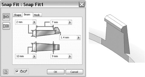
Click the Beam tab, set the beam length to 7mm, the Beam Width At The Hook setting to 9mm, and the Beam Width At The Wall setting to 10mm.
Click the Hook tab, and take a look at the settings; leave these settings at the defaults, and then click OK.
Use the Circular Pattern tool to pattern the hook around the opening for a total of three.
On the Solid bodies tab, right-click all of the solids, and choose Show All. Investigate the snap fit, and note the derived part has the mating half of the hook built in. Figure 19.19 shows the completed snap fit feature.
You can open the file named mi_19a_040.ipt in the Chapter 19 folder to experiment with the various snap fit settings. Use the work points to place hook and loop features to your liking. You can also open mi_19a_042.ipt for comparison. This file contains two halves of a simple plastic box. Interrogate the model features to see how the hook and loops were created in combination with extrude features to get a precise placement.
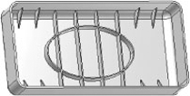
Ribs and webs are often used in plastic parts to prevent warping and add stiffness to thin wall parts. To create a rib feature, first create an open profile sketch to define the cross section. Then define the direction and thickness. If the rib feature runs perpendicular to the sketch plane, you can add a draft taper. By default, the profile extends to intersect the next face. To create a rib network, you can select multiple sketch profiles at once. Alternatively, you can create a single rib feature and then pattern and/or mirror it.
Open the file called mi_19a_044.ipt in the Chapter 19 directory of the Mastering Inventor 2010 folder, and then follow these steps to create rib features:
You'll notice there is a small diagonal line sketched in the corner of the part. This will be the sketch profile of the first rib feature. Select the Rib tool on the Create panel, and the sketch profile will be selected automatically.
Move your mouse pointer around the screen, and you will see the direction arrow adjust. It may be difficult to get the arrow to point in toward the rounded edge unless you rotate the view. Use the ViewCube to change the view, and then click the screen when you see the arrow point in toward the rounded edge. If you make a mistake, simply click the Direction button in the dialog box, and reset the direction.
Set the thickness to 0.5mm, and use the arrows to adjust the direction in which the thickness is applied. In this case, you want to use the Midplane option.
Click OK, and notice how the rib extends to the profile.
Next right-click Sketch3 in the browser, and choose Visibility to make it available for use.
Select the Rib tool again, and select the four lines and the ellipse as profiles.
Click the Direction button, drag your mouse pointer down to set the direction arrow and preview to extend toward the base of the part, and then click to set the direction.
Toggle the Extend Profile check box off and on to notice the difference in the preview. Ensure that this check box is selected so that the profiles do extend.
Set the thickness to 0.5mm, and use the arrows to adjust the direction in which the thickness is applied. In this case, you want to use the Midplane option.
To explore the Finite option, toggle the Extents solution to Finite, and type 5mm. This holds the depth of the ribs to 5mm rather than allowing them to extend to the base. Set Extents back to the To Next option.
Enter 5deg in the Taper input, and then click OK to create the rib feature.
You can use the Mirror and Rectangular Pattern tools to copy the first rib around the part as you see fit. Figure 19.20 shows the finished example.
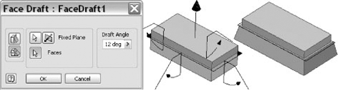
Taper or draft often needs to be applied to part faces so the part can be extracted from the mold in which is manufactured. You can create draft features by selecting a pull direction and then selecting the faces/edges upon which to apply the draft, or you can select a fixed face and apply drafts to the faces intersecting it. To explore both options, open the file called mi_19a_046.ipt in the Chapter 19 directory of the Mastering Inventor 2010 folder, and then follow these steps to create draft features:
Select the Draft tool on the Modify tab.
For the Pull Direction selection, click the yellow base face.
To select the faces, you will click the green faces near the edge that contacts the yellow base face. If you move your mouse pointer over the faces before selecting them, you will see that the edge closest to your mouse pointer will be selected. If you accidentally select an extra or errant edge, you can press the Ctrl key and deselect it.
Enter 5deg for the taper, and then click OK. You'll notice the top faces of the thin walls have been reduced because of the draft taper. To remedy this, you'll place a draft on the outside faces also.
Rotate the part around so you can see the red and blue faces, and then click the Draft tool again.
This time, click the Fixed Plane button on the left of the dialog box.
Select the red face for the Fixed Pane selection, and ensure the arrow is pointing out.
Select the blue faces for the Faces selection, enter 5deg for the taper, and then click OK.
You can open the file named mi_19a_048.ipt in the Chapter 19 folder to compare how creating the same tapers is made easier by the inclusion of the corner filet. Also note that you can use a combination of split faces and work planes to create draft features that will separate faces, as shown in Figure 19.21 and demonstrated in the file mi_19a_050.ipt.
Real World Scenario: Plastic Parts and Cooling Shrinkage
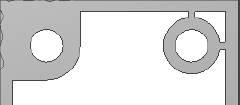
Designing plastic parts of uniform wall thickness is typically a fairly easy task when the part consists of a simple shell. However, when bosses and ribs are introduced, the resulting tees and feature intersections can create cross section thicknesses that are significantly thicker than the wall thickness average. As is often the case when modeling 3D parts, there is nothing to tell you that the model will not work in the real world, other than knowledge and experience.
The issue with adding bosses and ribs arises when the part is cooling after the molding process. Uneven part thickness will often result in sinking and deformation where the thicker walls cool slower than the rest of the part. The result can be a very disappointing resemblance to the eye-catching design you intended to create.
To deal with these problem areas, you can do one or more of the following:
You can use a textured surface to disguise uneven cooling.
You can create cores, corner reliefs, and tee inset features to eliminate thick areas.
You can use foam- or gas-assisted molding processes.
You can redesign the problem areas to avoid thickened walls.
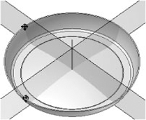
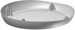
Although it will certainly vary depending upon the materials and process, a rule of thumb is to keep tee walls at 60 percent of the standard part wall thickness. As shown here, the feature on the left has some obvious problems with areas that exceed a consistent thickness. The feature on the right has been designed to perform the same function and yet maintain a desirable wall thickness throughout.
- Set up plastic part templates
Creating templates that are specific to your design work saves time, reduces the tedium of initial part creation, and is an efficient way to create consistency from one design to another.
- Master It
How do you create a template with design information focused on plastic part design?
- Create thicken/offset features
When creating plastic parts, you will often find that working with surfaces allows you to achieve more free-form shapes than working with solids. Once the surfaces are created, you'll need to give them a thin wall thickness.
- Master It
How would you create a plastic part file with many curved, free-form elements?
- Create shell features
Shelling solids parts and features is a common way to create base features for plastic parts. Once the shell feature is created, other features can be added to it.
- Master It
You want to create a shell feature but need to have the thickness of some faces be thicker than the rest. How would you accomplish this?
- Create split features
Many times you may want to establish the overall shape of the feature and then divide the shape into separate parts of the overall design. You can use the Split tool to do just that and more.
- Master It
You have a plastic part that needs to have a raised face for a rubber grip applied during the manufacturing process. How would this be done?
- Create grill features
Grill features allow the inflow or outflow of air through a plastic thin wall part. Grills can be created with a number of subfeatures such as islands, ribs, and spars, but only the outer profile of the grill is required.
- Master It
How would you determine the area of a grill opening to determine the airflow that it can handle?
- Create rule fillet features
Rule fillets can be an extremely efficient way to apply fillets to many edges throughout the design that meet the same rule criteria.
- Master It
How would you apply fillets to all the edges that are generated by extruding a shape down to an existing set of base features?
- Create rest features
Rest features can be used to create level platform faces for mounting other parts to an irregular plastic part face.
- Master It
You want to create a rectangular pocket on the inside of a plastic housing to hold an electronic component. How would you do this?
- Create boss features
Boss features are ideal for creating fastener-mounting standoffs for thin wall plastic parts. You can use the Boss tool to create both halves of the fastener boss.
- Master It
You want to create multiple boss features around the perimeter of a flat, pan-type, base part, but you know this base part is likely to change size. How would you set up the boss features to adjust to the anticipated edits?
- Create lip and groove features
When designing plastic parts, it is often required that one half of a design fit into the other half. The Lip tool allows you to create both lip and groove features for these situations.
- Master It
You want to create a groove around the edge of an irregular, curved edge. How would ensure the lip on the corresponding part would match?
- Create snap fit features
Snap features are a common way to join plastic parts together so that they can be disassembled as needed. You can use the Snap Fit tool in Inventor to quickly create these features.
- Master It
How would you create a U-shaped snap fit with the Snap Fit tool?
- Create rib and web features
Ribs and webs are often used to add rigidity and prevent warping during the design of plastic parts. You can add ribs based on open profile sketches in Inventor.
- Master It
How would you create a network of ribs that are evenly spaced, where some of them contain different cutouts than others?
- Create draft features
Because plastic parts must be extracted from a mold during the manufacturing process, drafted faces must be included to ensure the parts can indeed be extracted from the mold.
- Master It
You want to create drafted faces on a complex part containing various shapes within it. How would you do this?