
Walls are one of the most profound features of Revit Structure. As a wall is modeled, all aspects of that wall's functions are considered—the structural usage, the type of wall, and even architectural considerations. Also within the initial design of a wall, the cover for reinforcing is specified. Learning how to create and work with wall systems is a must, but it is easy to accomplish.
Walls, like slabs, floors, and roofs, are unique in that they are all system families. This means they are completely controlled, manipulated, and created within the current structural model. You do not import a wall type into a model. It also means that walls can change dynamically as the model changes. When a wall is "constrained" between two floors, for example, the actual dimensional difference between the floors influences the height of the wall. If a floor height changes for any reason, so does the wall height.
It is important to note right off that wall types that are to be repeated through many projects should be added to a company template. To learn more about template creation, refer to Chapter 2. If a wall object has been created in another project, the wall style can be carried into the current model by simply copying and pasting the wall into the current model from the existing one. Although this is often frowned upon in other drafting applications, Revit Structure is a database that fully allows copying and pasting without residual, unexpected side effects such as extra layers, blocks, and even shape files, which might otherwise corrupt a drawing.
The first type of wall system to be covered will be a basic wall. Don't let the name fool you—it can be anything from a plain concrete wall to a complex wall system with structural and architectural elements combined. The basic wall type, however, will certainly be the most common wall type used. Revit Structure ships with 12 predefined basic types. Some of these wall types will be fine to use as is, and some of them will be used as a starting point for a more complex wall system.
In this chapter you will learn to:
Place walls in your model
Create new walls
Modify walls in place
To add a new basic wall, you first need to be in either a plan view or a 3D view. You should also have all primary levels defined, but it is not imperative. After all, the power of Revit Structure lies in the fact that changes are propagated throughout the model. Also, it is recommended that you place walls in a plan view and not a 3D view. You will have much more control, and you are less likely to make mistakes. At the top of the Revit Structure 2010 graphical user interface is the Ribbon. Walls are easily created using this interface. On the Home tab
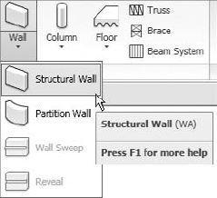
The command process in Revit Structure is quite intuitive. You select your command (in this case Structural Wall), and Revit Structure will change the active ribbon to display a contextual ribbon filled with tools that apply to that element (see Figure 6.2). When you exit the command, the contextual ribbon for that specific command will be dismissed. This greatly reduces the clutter found in most traditional CAD programs, where all the toolbar commands surround the display area.
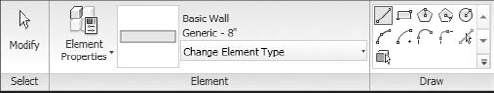
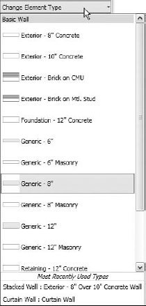
On the contextual tab, several buttons will stand out. The most important of the buttons is what is called the Type Selector (see Figure 6.3). This will display a list of the defined wall types found in this specific project. This list can simply be just a few wall types, or it can be extremely long depending on the size and stage of your project. We recommend that this list be as short as possible and that you adhere to company-wide naming conventions. There is nothing worse than having exact duplicate wall configurations with differing type names to choose from. As you start the Wall command and the Place Structural Wall tab appears, the first thing to do is select a wall type from the Type Selector.
When you select the item from the Type Selector, Revit Structure continues to provide choices from the Place Structural Wall tab and the Options bar below it. The first decision is how you will place the new wall in your model. You can either match existing geometry in the model, or you can use a Draw tool and draw the wall from scratch.
By using a Draw tool, you are telling Revit Structure you want point-by-point placement of your wall. You will be prompted to pick a point in the view window. Click to enter the wall's start point. Because Revit Structure does not have an actual command prompt, it has a status bar to guide the user. This comes in handy for more convoluted commands. Once the first point is selected, you will see a blue alignment line. This takes the place of the traditional "ortho," or polar tracking. If you move your cursor straight in any direction, your wall will snap to a horizontal or vertical axis automatically (see Figure 6.4). You can configure additional snap settings using the Manage tab
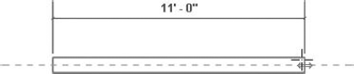
As you sketch the wall, a blue dimension appears. This is called a temporary dimension.
Instead of having to eyeball a second point, you can type in a distance value instead (see Figure 6.5), because when you see the blue dimension value Revit is "listening" for keyboard input. Since Revit Structure is, by default, using feet and fractional inches in Imperial units, you can type in the value without the foot mark. For example, if you wanted a wall that was 50′-0″ long, you could simply type in 50. Revit Structure accepts that this value is in feet. If you wanted the wall to be 50″ long, you could enter 0 50 or 0-50, or you could type 50″, including the inch mark. If you wanted 50′-6-1/2″, you could enter 50 6 1/2. Also, Revit Structure will accept equations as you draw the wall. If you wanted a 50′-0″ long wall, for example, you could type =25*2. Once the second point is selected, Revit Structure will place the end at the resulting distance of the equation. Another neat option is that you can use alternative units for any distance input. Even though your model may be in Imperial units, if you provide a value of 20m, for example, Revit will provide a 20-meter distance regardless of the project unit setting.
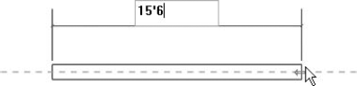
Figure 6.5. You can type temporary dimensions using any valid input distance method and in any unit format.
Normally, the process will be to sketch the walls, but if geometry is already placed in the model, it may be tempting to just select that geometry.
By using the Pick Lines button, you are telling Revit Structure that your method of wall placement will be to select existing geometry in the model. You typically use this approach when you are referencing an architectural model from within a structural model. In some cases, this will be a 2D architectural CAD file. We recommend that you proceed with caution while picking geometry using this method. It is possible the CAD data can contain walls that are not perfectly straight. If this is the case, and you are adding a new wall by picking the CAD geometry, Revit Structure will report the issue (see Figure 6.6).
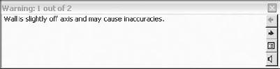
Revit Structure will generate a warning that can be bypassed. Although it is tempting to ignore, we suggest that you ensure your wall is being drawn straight and accurately. This warning can also be expanded to see exactly which wall generated the error. Revit Structure will list the error and then break the list down to the specific item(s) that are suspect. Once the items are selected, you will be able to find the "crooked" walls in the model. At that point, you can delete the offending item. Again, we recommend that you go ahead and delete the wall instead of trying to adjust it or leaving it in the model non-orthogonal. See Figure 6.7 for an illustration.
The Pick Lines method is also useful for adding walls to a sketch. Many times it is useful to use drafting lines in place of walls to establish important layout dimensional constraints. In preliminary stages of a project, it is sometimes beneficial to approach a model in this mind-set. Sketching the lines and then adding the walls afterward in many cases is much easier and actually safer (see Figure 6.8). For more information on drafting lines and sketching, see Chapter 9.
Later, once the perimeter extents have been established, you can place the walls by selecting these lines. Simply start the Structural Wall command, and then click on a line. A useful method is to use the Tab key to pick lines. While running the Wall command, you can pause your cursor over a single element. Once the item highlights, press the Tab key. All connected elements will become highlighted.
Since you are basically drawing in 2D, what about the height of the wall? Don't you need to "extrude" it? The answer is no. You can set the height based on either a level or an increment. The results would then look like Figure 6.9.

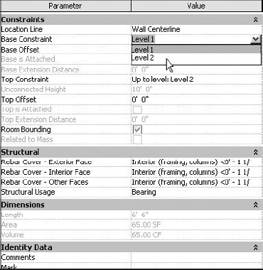
As mentioned earlier, walls are special because they can be constrained to project levels. This means that the base and the top can both be "locked" to a level (see Figure 6.10). In other words, you can set a wall and forget it.
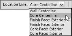
To do this, while the Wall tool is active, glance at the Options bar. It has a drop-down to handle the Height or Depth constraints (Figure 6.11). It is automatically assumed, unless specified otherwise, that you will create the wall using Depth and "build a wall" down to a level below. Once you select a depth or height, you can choose the level it will be constrained to in the adjacent drop-down list. If you choose Unconnected, you can simply provide a fixed height or depth value. We recommend that you specify a level in lieu of an unconnected height or depth when possible. Once you start sketching the wall or selecting geometry to use as a guideline, you need to consider and choose the Location Line setting, which is similar to the notion of text justification, on which the wall will be defined.

Possibly the most important item on the Options bar is the location of the wall (see Figure 6.12). This determines what the points you pick/place mean. Do your points indicate the face of the structure or the face of finish? Do you care? You should, because this can ripple through a project in a negative or a positive way. When you are laying out a wall, be aware of the fact that, while the justification of a wall can always be modified, it is not always easy to do so toward the end of a project.
There are six choices for locating the justification of the wall, as explained in the following sections.
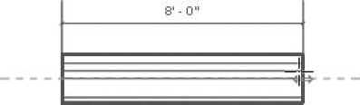
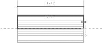
The Wall Centerline option calculates the centerline of the wall based on the two outermost faces or overall thickness of the wall (see Figure 6.13). It could be made of gypsum or some lightweight finish, or it could be a structural element such as CMU or concrete. While this is fine for a single-layer-type wall such as a concrete foundation wall or concrete masonry unit (CMU) wall, it is not recommended for a compound wall such as a CMU wall with a brick veneer. Also, walls with finishes don't lend themselves well to this justification.
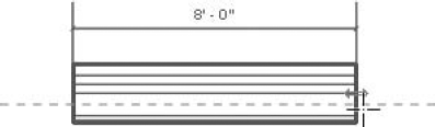
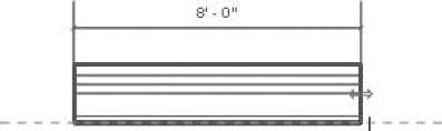
The Core Centerline option allows you to justify the wall about the centerline of the structural width/thickness of the wall (see Figure 6.14). In the example used here, the compound wall is 8″ CMU with 2″ of rigid insulation, a 2″ air space, and a 4″ brick veneer. The justification of the wall is based on the center of the CMU layer because it is the core boundary. This helps in the placement of the structural face of a core layer.
This one, we believe, is self-explanatory. The justification of the wall will be to whichever face is to the outside. If you select an existing wall, a flip control symbol will appear, and it is always located outside the exterior face of the wall. As you are placing a new wall, however, the inside and outside may not be what you expect. You have the option to press the spacebar to swap the interior and exterior faces of a wall. To do this, use the following steps:
Select the Structural Wall command on the Structure panel of the Home tab.
Select a compound wall type such as Exterior – Brick on CMU.
Change the Location Line value to Finish Face: Exterior.
Click the start point for the placement of the wall.
Press the spacebar.
Notice that the wall will flip about the justification axis, as illustrated in Figure 6.15.
This justification allows the wall to be placed using the finished face of the inside of the wall. This is normally an architectural finish and is probably the least common of the six choices, but it is still sometimes useful or necessary (see Figure 6.16) where codes require minimum clear distances between the finished walls, such as exit corridors, for example.
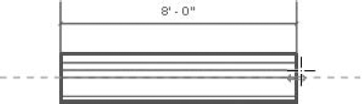
This option justifies the wall to the face of the structural element of the wall. The face it chooses is the side facing the exterior. Usually this is in the middle of the wall core, as shown in Figure 6.17. This allows you to justify the wall as if there were no architectural elements, and the insulation, air space, and brick layers are ignored.
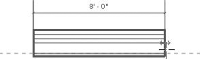
Like Core Face: Exterior, this option justifies the wall based on the inside face of the structural element. Any finishes on the inside of the wall will be ignored. See Figure 6.18.
Exercise: Justifying Walls
As a practice for the wall justification, perform the following steps:
Start a new project model and go to the Level 1 plan view.
Change the Detail level to Medium so that wall layers will be visible.
On the Structure panel of the Home tab, select the Wall button.
Assign the wall type Exterior – Brick on CMU on the Type Selector.
Change the Height to Level 2.
Change the justification to Finish Face: Exterior.
Pick a start point.
Toggle the Chain check box on (if needed).
Draw a wall 25′-0″ straight to the right. If the justification location line is to the top, press the spacebar to flip it.
Draw another wall 25′-0″ straight up. Continue to the left and down to form a box.
Although this is simply a box shape, it is important to understand how Revit Structure works and, more important, what it expects from the end user. Yes, placing walls is simple, but an eyes-open approach is needed to get the desired results. Although all of these options can be fixed later, getting the most accurate placement initially is crucial to a successful project. See the following illustration for the finished walls.
If you choose to sketch the walls, some additional tools will be available on the Options bar. These options will allow you to draw the walls in the geometry you need.
Now a final word about location line placement. Often when you copy and paste or use any other method of getting walls into your model, you might forgo worrying about the Location Line setting initially. But what if later you need to make adjustments to the wall type, such as getting rid of extra material layers you don't need structurally? If you simply adjust the Location Line setting to be a core face rather than a finish face, then when you swap to a new type the core will stay in the same position. If you need to then adjust core thickness, consider changing the location line to the core side that is in the proper location and then adjusting the type. This basic procedure will keep the primary concern of the wall, the core, in a consistent and correct location.
It does seem redundant to keep drawing walls piece by piece. After all, most drafting programs allow users to draw any shape they choose. Revit Structure is no different. With the proper height and base constraints and the proper justification, Revit Structure will allow you to "sketch" any desired shape. As a default, the Line method is selected for the placement of any new wall. To the right of the Line choice is the Rectangle method. Let's explore a couple of the other options available.
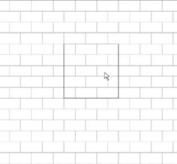
The placement of a wall using the Rectangle method involves these steps:
On the Structure panel of the Home tab, click the Wall button.
Set the Height/Depth and Location Line to the desired settings.
Click the Rectangle button.
Pick a corner point for a rectangular wall configuration.
Move your cursor in an angular direction.
You will see the walls form, but they may be positioned incorrectly. Remember, before you place the second point, you can press the spacebar to flip the orientation of the wall elements about the Location Line. Unfortunately, you will have to adjust the Temporary Dimensions after you finish the rectangle because you cannot define them before or during placement.
Pick a final point to finish the rectangle.
The other polygon shapes we can create are inscribed polygon and circumscribed polygon.
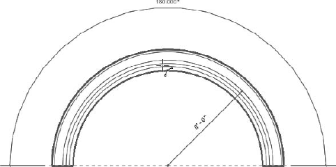
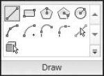
For curves or arcs there are several other tools: Circle, Start-End-Radius Arc, Center-Ends Arc, Tangent Ends Arc, and Fillet Arc. Let's take a closer look at the placement of a wall using the Start-End-Radius Arc method, which involves these steps (see Figure 6.19). This method is easiest to use in some cases because you don't have to know where the center of the arc is located.
On the Structure panel of the Home tab, click the Wall button.
Click the Start-End-Radius Arc button.
Pick the start point of the arc; with the first two points you select, you are defining the chord of your arc.
Pick the end point of the arc.
Either pick a point along the arc or type in a radius distance. Remember that if the justification is incorrect, you can press the spacebar to flip the wall.
There are other wall draw options as well (see Figure 6.20).
Let's try another method. Revit Structure does not have an actual Fillet command that will allow you to select the wall and add a radius at a later time. It does, however, have a Fillet Arc button built into the Draw panel during wall creation.
The creation of a filleted set of walls using the Fillet Arc option is as follows:
On the Structure panel, click the Wall button.
Create any corner condition.
Select the Fillet Arc button from the Draw panel.
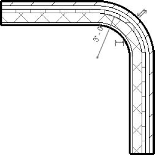
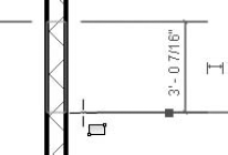
Turn on the Radius check box on the Options bar, and enter a distance of 3′-0″ (see Figure 6.21). If you want, you can dynamically place the fillet arc wall segment by skipping this step, moving to step 5, and picking a point that describes where the fillet arc should go.
Click the two walls, and the fillet arc is added (see Figure 6.22). Note that the radius is applied to the centerline of the walls. When you sketch using the Line or Rectangle button, you also have the option to specify a radius, in the same way as in step 4 and shown in Figure 6.21, which will cause Revit to add a fillet radius at each intersection of your sketch, as you sketch.
Now that we have drawn some walls in the model, it is time to see how we can further manipulate them. Simply placing a wall and then changing the visible options is literally just scratching the surface of what can be done. There is an entire dialog box filled with options and settings we can use to configure our walls. Once the wall(s) have been added to the model, we can modify the individual Element properties of each wall itself.
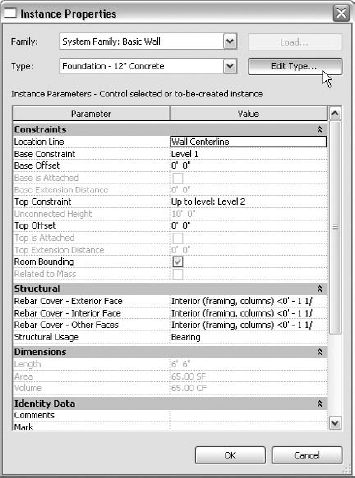
By placing a wall and then selecting Element Properties, you gain access to even more settings than were available on the Options bar. These settings are called instance parameters. This means that the changes will pertain only to the wall(s) selected. If you would like to change every wall instance of that wall type in the entire model, you can access the type properties by clicking the Edit Type button. This is common not only in walls but in almost all families in a Revit Structure model (see Figure 6.23).
To gain access to the Instance parameters of a wall using the Instance Properties dialog box, follow these steps (see Figure 6.24):
Type parameters of a wall are settings that define what a wall is. These parameters, if modified, will influence every matching wall type in the model. So, if you have a CMU wall and you change the Type parameter called Material to Brick instead of Concrete Masonry Units, you have just changed every wall of that type to be a brick wall. So, given that, you must make changes deliberately and thoughtfully. To access these properties, first select a wall, and then click the Element Properties button on the Element panel. Next, click the Edit Type button at the top of the dialog box, as shown in Figure 6.25.
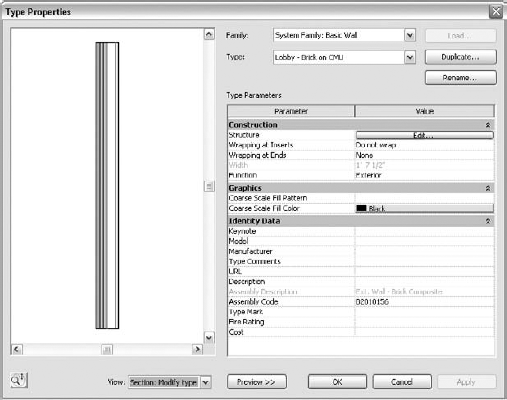
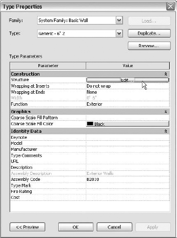
Once you click Edit Type, the Type Properties dialog box displays (see Figure 6.26).
It is important to get into the practice of creating new wall types when you are changing Type parameters and don't intend to alter the existing walls in your model. If you already have the Instance Properties dialog box open, then follow these steps to edit the Type parameters for a wall:
Click the Edit Type button.
Click Duplicate.
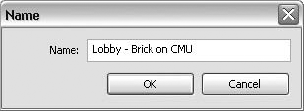
Rename the wall type to something that makes sense (see Figure 6.27).
Use the Type Properties dialog box when you plan to either change the current wall type globally or create an entirely new wall type. This sequence steps you through the process:
Click the Preview button at the bottom of the Type Properties dialog box. The dialog box expands to display a graphic of the wall (see Figure 6.28).
Beneath the preview is a View drop-down list. Select Section: Modify Type Attributes (see Figure 6.29).
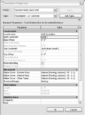
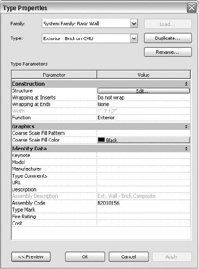
Figure 6.26. The Type Properties dialog box allows you to edit every wall for that type in the entire model.
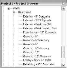
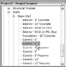
Another way of managing your wall types in Revit Structure is to use the Project Browser (see Figure 6.30). As you scroll down the list, you will come to a portion in the browser where families are listed. If you expand families by clicking the plus sign (+), you will see the Walls category. Here, the walls are broken out into the three categories: Basic Wall, Curtain Wall, and Stacked Wall. If you expand the list further, you can simply double-click on a wall type to access its Type properties. This method is slightly different than selecting a wall from the drawing area—with this method you have access only to the properties that will change all of the walls of this type in the entire model.
To create a new wall type from the Project Browser, perform these steps:
Notice you have access only to the Type properties. This is a good way to ensure you are editing only the proper wall. As mentioned earlier, there is a small sampling of walls to choose from in the out-of-the-box Revit Structure templates. You will almost certainly need to start creating your own walls at some point. Usually "some point" is the first stage of your first project.
Now that you have the basics down, it is time to create a new wall type. Depending on how you plan to use the wall type, this can be either easy or somewhat difficult. Keep in mind that the amount of effort you put into the wall at this stage of the model can have positive effects down the line when it comes time to add sections and elevations.
Let's begin with a very simple wall. Create a new model, and then in the Project Browser, scroll down to the Walls category within the Families list and then into the Basic Wall category. Right-click on Generic – 6″ and duplicate the wall type. This will create a new type of the same name with an added "2" (see Figure 6.31). Once it is created, right-click to open the context menu for the new wall type and rename it if so desired.
Use the following procedure on the new project model where we will adjust a new wall type (see Figure 6.32):
Double-click on the new wall type.
In the Type Parameters section of the Type Properties dialog box, click the Edit button in the Structure row.
In the Edit Assembly dialog box, make sure the Preview window is open and that the View drop-down is set to Section: Modify Type Attributes. This is important because otherwise you can't access some of the buttons we will be using (see Figure 6.33).
Note that before you start modifying this wall, you should plan each change carefully. Pressing the Esc key will cause you to lose all of your changes. If you make a mistake, click the Cancel button and redo the procedure. This does take practice and patience.
Revit uses wall layers to not only generate the appropriate look for a wall but also to instruct Revit on how to connect the various elements when they intersect other walls, of the same type or a different type. Core layers join to core layers, and subsequent layers join according to the hierarchy they are set to. Controls for physical materials like Substrates can supersede others such as Thermal/Air Layer.
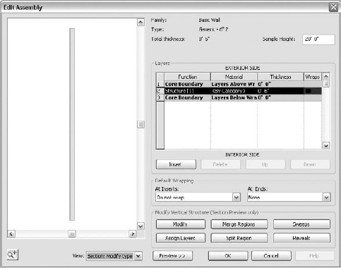
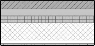
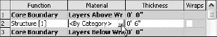
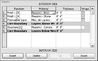
Notice a section called Layers in Figure 6.33. Two core boundaries surround a wall core. When you build a wall, anything that goes between the core boundaries is considered the core (typically structure). Above the layers you see EXTERIOR SIDE and below it you see INTERIOR SIDE. This information becomes important when it is time to set the justification (see Figure 6.34). The following procedure will step you through the process:
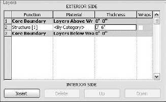
Figure 6.34. The Layers settings determine the materials and their thicknesses as they will be applied to the wall.
Click <By Category> in the Material column. A builder button will appear in the right end of the edit box (see Figure 6.35).
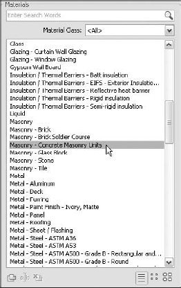
Click the builder button to open the Materials dialog box.
In the Materials section, select the material called Masonry – Concrete Masonry Units (see Figure 6.36).
Click OK.
In the Thickness column, assign a thickness of 8″.
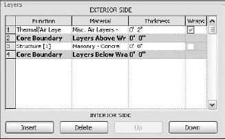
Click on the number 1 row (next to Core Boundary).
Click the Insert button. This will create a new layer outside of the Core Boundary.
Change the new layer function from Structure to Thermal/Air Layer.
Click the material and then click the builder button.
Select Misc. Air Layers – Air Space.
Click OK.
Give it a thickness of 2″ (see Figure 6.37). The preview is starting to change. Notice the row you select in the Layers section is highlighted in the preview window. This is true only in the section view.
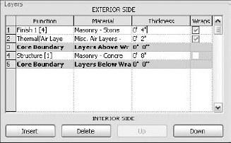
Select the number 1 row again, and click the Insert button.
Change the Function value to Finish 1.
Change the Material value to Masonry – Stone.
Click OK.
Change the Thickness value to 4″ (see Figure 6.38).
If you click in the preview window, notice that you can click your wheel button to pan around (see Figure 6.39). If you roll the wheel button forward or backward, you can zoom. Zoom in closer and to the bottom. You can also right-click to bring up the context menu and choose from available view options as well as click the Steering Wheel icon in the bottom-left corner to display the Steering Wheel tool.
A best practice that some follow is to reserve Finish 1 for exterior placed layers and Finish 2 for interior layers. This is often used to aid in joining layers at intersections. It also can be of help when reviewing layers in a wall type. Now we are going to split and merge the bottom 3′-0″ of the wall to create a compound wall situation.
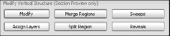
Underneath the Layers area where you were just working you will see the Modify Vertical Structure section (see Figure 6.40). This would not be available if the preview was not set to Section. Since it is set, you can chop up the wall. Before you do, though, click OK to preserve your work up to this point. This will place you back in the Type Properties dialog box. The following procedure will step you through the next process:
Click the Edit button next to Structure to return to the Edit Assembly dialog box.
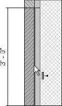
Click the Split Region button.
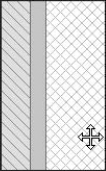
Your cursor turns into a knife. As you place your cursor over layers of the wall in the preview window, Revit Structure will provide a temporary dimension at your cursor. Move 3′-0″ up the wall, and split the 4″ stone material (see Figure 6.41). This may take a couple of tries to get right. Remember you can zoom in and pan. Your cursor needs to highlight the layer edge but be slightly inside the layer to cut the layer properly.
In the Layers section, add a new layer at row 1, specifying Function: Finish 1 and Material: Masonry – Brick (see Figure 6.42). Do not give it a thickness.
Using the Split Region command, split the air space at the same 3′-0″ height.
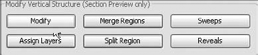
Click the Assign Layers button (see Figure 6.43).
Make sure Row 1, your brick material layer, is selected/active in the Layers section.
Click the Merge Regions button.
Hover your mouse over the line between the brick and the air space, below the 3′-0″ cut line. You will see that an arrow forms. The direction in which the arrow points is the direction in which the material will merge. Merge the brick into the air space (see Figure 6.44).
Click OK.
Click OK again.
You have a new wall type.
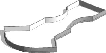
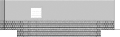
In some cases, the architectural finish extends above the core structure to form a small parapet. You can do this in Revit Structure. First, place some instances of your new wall in the model. It has been our experience that, just because something looks correct in the editor, it may not be in the model. It is also wise to test how the wall is joining in corners (see Figure 6.45); your sketch may look different!
In many cases, the architectural finish will extend above the bearing of the wall to form a small parapet for drainage blocking or to conceal structural elements. This can also be accomplished in Revit Structure with the following steps:
In the Project Browser, double-click on the new wall style, or open an existing compound wall.
Click Edit in the Structure row.
Zoom in to the top of the wall.
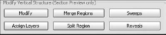
Under the Modify Vertical Structure (Section Preview Only) area, click the Modify button (see Figure 6.46).
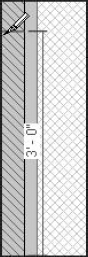
Select the top line of the stone layer. Notice the padlock.
Unlock the padlock by clicking on it.
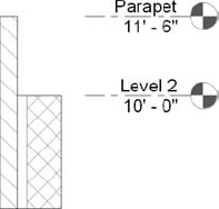
This releases the top wall constraint so that it's independent of the wall structure (see Figure 6.47). Once the wall is placed in plan, the wall can be edited via the Element properties, in a section or in a 3D view. We recommend that you make modifications using a section view to maintain accuracy. You can edit the Element properties while looking at the wall in section to ensure the offset is as accurate as you want. If this is an extensive feature affecting many walls, it may be a good idea to set up a parapet level and extend this item to a level. You will have to use the Align and Lock feature to establish a dynamic link between the level and the top of the brick parapet. Once the wall is selected, you will see two blue arrows. One controls the finish and the other controls the structure. This indicates that the wall has been successfully released.
Click OK in this dialog box.
Click OK again.
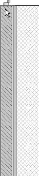
This puts you back in the model. If you have this wall placed, cut a section through it. In the section, select the wall. See the two blue arrows? It helps to use Detail Level: Medium so you can really see the layers. They can now be independently moved, as you can see in Figures 6.48 and 6.49.
Once the wall is physically placed in the model, the battle is only half over. Revit Structure has many functions that allow you to modify the wall once it is in place.
Once a wall is placed in a model, additional functionality is often needed. Adding an opening—penetrations, for example—and allowing the wall to attach itself to a sloping slab or a roof are a couple of tasks that often need to be done.
Openings are added after a wall is placed in the model. This can be done in an elevation and can be accomplished in two ways: editing the wall profile and adding a wall opening. The first method is to physically edit the wall profile. To add an opening, as well as extend the wall beyond its perimeter, perform these steps:
Add a wall to a new model. It can be a new wall type or a wall that has been predefined.
Create an elevation view looking at the wall.
Select the wall, and the Ribbon will display the Modify Walls tab.
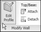
Within the Modify Wall panel, click the Edit Profile button (see Figure 6.50).
The wall is now shaded and outlined with sketch lines. If you look at the Ribbon, you will notice that is has switched to the Modify Walls
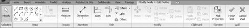
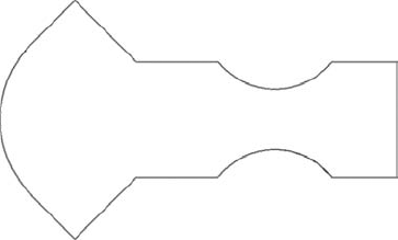
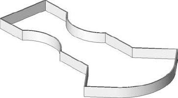
Click the Rectangle button (next to Line). On the Options bar, you will notice choices similar to when you were placing the walls originally; you have controls for Offset and Radius. Draw a rectangular opening in the middle of the wall (see Figure 6.52—your wall may look different).
Now, draw a step in the bottom of the wall (see Figure 6.53). You do not need to be accurate for this example, but you do need to split/trim and remove the bottom portion of the sketch so it looks like Figure 6.53.
Click the Finish Wall button on the Wall panel, on the far right end of the Ribbon. This will end the change and assign the new wall profile (see Figure 6.54).

Another technique at your disposal is the Wall Opening tool. This tool was originally designed to create openings in curved/arc walls because those walls cannot have their profile edited as we did in the previous example. These openings can be placed in an elevation view or a plan view and can only be rectangular in shape.
This tool is a bit awkward to use. For example, in an elevation view you can start sketching based on an edge or on reference planes, but setting the opposite corner accurately can be difficult. You then have to adjust the opening to achieve the size you need. In plan views you can see only the plan limits of the opening. You will have to define the opening height via the Element Properties dialog box or by switching to an elevation view. But understanding the opening parameters can aid in this work substantially. To add a wall opening in a plan view, perform these steps:
Starting with a plan view, add an 8″ masonry wall into a new model.
Click the Modify tab, and on the Opening panel click the Wall button.
Click your wall to select it.
Now drag your cursor along the wall. Revit Structure will provide temporary dimension strings so you can determine the width of the opening being placed (see Figure 6.55). Release the mouse button when you reach the desired width.
Click Modify or press Esc to cancel the Wall Opening tool; now select the wall opening. The Ribbon will switch to the Modify Rectangular Straight Wall Opening tab.
Click the Element Properties button on the Element panel. This will bring up the Instance properties for the opening (see Figure 6.56).
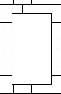
Depending on previous actions, the values will vary and be set to unpredictable values. That is fine since we will assign proper values in a specific sequence in order to create the opening we need. For starters, we want an opening that doesn't rely on the level above it. We also need to have an opening of 8″ above the current level and 5′-4″ tall.
Change the Top Constraint parameter to Up to Level: Level 1. This will disconnect the opening from Level 2.
Change the Top Offset to 6′ and the Base Offset to 8″. The Unconnected Height will adjust to an even 5′-4″ tall.
Click OK to close. Switch to an elevation view to see that the opening lines up nicely with the horizontal masonry joint lines (see Figure 6.57).
By using the Instance parameters, you were able to adjust the wall opening without having to go to an elevation view. In your plan view, you would still adjust the opening plan extents by using the shape handles; there are no Instance parameters for opening length and placement. The Align tool can come in handy to adjust the width accurately.

It is important to understand that these opening techniques can cause a wall to lose its room-bounding behavior if the opening touches the level that an adjacent room is also on. If a wall must retain its room-bounding behavior, then openings should be created using a component family instead. Since Revit Structure does not have Room commands, it might seem an unnecessary distinction, but if you collaborate with other firms using Revit Architecture or MEP, your walls may need to be able to provide room-bounding behavior. This is the sort of thing that a collaboration meeting should include.
A basic wall is restricted to maintain the same thickness overall with the exception of adding sweeps and reveals. There will be times where parts of a wall do not have a finished face that is aligned. In these situations, you can create a stacked wall instead.
A stacked wall is exactly what the name implies. It consists of two or more predefined walls that can be combined—stacked one on top of another to create a composite wall system, where the finished faces are staggered. Technically the walls are not required to have their layers align or be the same material, but in practice most walls share a common structure and the veneer varies.
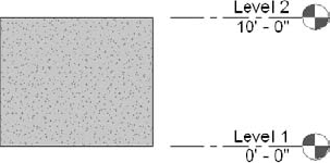
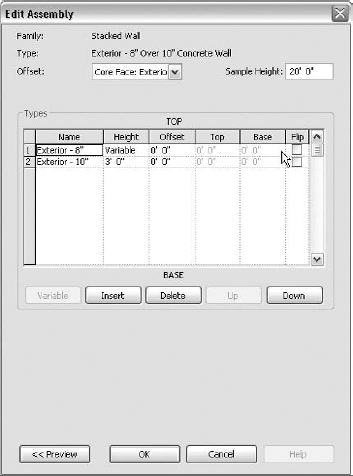
In the Project Browser, in the Families category, scroll down in the list of families until you come to Walls. You will see Basic Wall, Curtain Wall, and Stacked Wall. Expand the Stacked Wall category, and you will see a single type called Exterior – 8″ Over 10″ Concrete Wall. If you double-click this wall, you will open the Type Properties dialog box. Now click the Edit button in the Structure row to open the Edit Assembly dialog box, as shown in Figure 6.58.
As you can see, the options differ from those offered in the Basic Wall Edit Assembly dialog box. With the basic wall, you are trying to define the wall laterally, layer by layer. With the stacked wall, you are defining the wall vertically, piece by piece. In other words, you build each piece in advance and then assemble them here.
In the Edit Assembly dialog box is a Types section. Here you can assign basic walls to form your stacked wall type. The default stacked wall, for example, consists of an Exterior – 10″ Concrete wall and an Exterior – 8″ Concrete wall. These are two basic walls added to the Types field. To add a new wall to the stack, click on either row 1 or row 2. Below the Types field, you will see an Insert button. Once you click the Insert button, a new wall type row will be added to the stack. You can move each wall type up or down. You can add as many walls to the stack as you need.
In the upper-right corner of the dialog box is a Sample Height field, which governs how tall the sample will be in the preview window. Usually when building a stacked wall, it is a good idea to set this to the floor-to-floor height that the wall will be constrained to. (If it is 12′-0″ from Level 1 to Level 2, set this value to 12′-0″.) This helps to avoid unexpected results as you place the wall in the model.
Using stacked walls can save you time. They can also pose interesting problems for openings or other hosted elements like doors or windows, if these openings span more than one of the walls. Review the help documentation for more information regarding architectural elements such as doors and windows.
A common issue with walls often involves a pitched roof. You will almost certainly find yourself in a situation where you have a wall that must be extended to meet a roof.
A nice function in Revit Structure is the ability to attach the wall to a sloping or pitched floor/roof element. The following exercise explains how to attach a wall to a roof.
Exercise: Attaching a Wall to a Roof
To begin download walls.rvt from the book's website. It contains some walls and a roof.
Select the wall at the near gable end.
In the Modify Wall panel, you will see an Attach button under Top/Base. Click this button.
The Options bar changes for you to select either a top or a base. It is imperative that you notice this and select the proper option.
Select Top if needed.
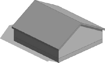
Now select the roof. The wall will extend to touch the roof, as shown in the following illustration.
The walls can be joined to any floor/roof structure. If that element then changes angle, the attached walls will change along with it.
Repeat the procedure on the other side.
The ability to join walls in Revit Structure to a floor/roof can be quite helpful (to say the least) when you are trying to match unusual geometry. You must, however, have the element in your Revit project—you cannot attach to a linked floor/roof from another model.
- Place walls in your model
When you are adding walls to your Revit Structure model, you can rely on the fact that you will get both the width and height of the wall depending on that wall's type, as well as the height constraint you have set. Once the walls are placed in the model, you can easily adjust them to change when the building changes.
- Master It
Walls are quite simple to place in the model, but they can also be inaccurate if they are not added to the model deliberately. What are three things to look out for when placing walls in the model?
- Create new walls
There is a good amount of functionality included in the process of building a new wall type. Furthermore, walls are a system family, which can be used as a basis for any additional wall type you may wish to create.
- Master It
The walls in the default Revit Structure template are not going to be sufficient. Revit Structure provides the capability to modify a preconfigured wall type to suit your condition. Describe the procedures for:
Creating a basic wall
Creating a stacked wall
- Modify walls in place
When a wall has been placed, some additional functions are allowed in Revit Structure for modifying the wall.
- Master It
Walls must conform to various conditions vertically, such as odd openings and a stepped base profile. Also, if you have a pitched roof, the tops of the walls need to be extended to meet the roof. Explain how these procedures can be performed.