
One aspect of using Revit Structure for BIM is creating documentation to help display the information that is part of the Revit Structure model. The method for creating these documentation pieces is pretty much the same as it is in a 2D environment. You create sheets with title blocks and then add plan views and sections or details to the sheets along with schedules and notes for plotting. In addition, you may include a sheet index and perhaps a few key plans if required. Since all this information is stored in one database, Revit Structure can help keep track of everything as the specs change during the coordination process.
You can easily keep track of these changes for others to see by using Revit Structure's built-in revision tracking. As changes are made and tagged in views, Revision Schedules placed in title blocks are automatically updated.
In this chapter you will learn to:
Create a title block to display project information
Create a Revision Schedule to your company standards
Explore the behavior of the various view types when they are placed on a sheet
Produce a drawing list/sheet index to keep track of your issued sheets
Control the behavior of revisions in your project
Sheets are a category in the Project Browser for organizing a system family called Sheets. Inside this system family you place other views and external component families such as title blocks. Sheets are another type of view used to display information from the model. They are somewhat like a drafting view in that they do not display information directly from the model or have a view range, but they are much more powerful in managing the information that is put inside them.
Similarly to any other views, you can place line work and annotation directly into sheets. In order to display model information, you can place other views that display the model elements inside sheets. Once other views are placed within a sheet, Revit Structure keeps track of their references and placement on the sheet as well as manages the various scales that are required to show the various levels of detail in a plan or detail view. Since sheets don't have a scale of their own and they manage the scales of those views that get placed within them, it is no longer necessary to worry about scale factors, text height, and dimension settings. As these views get moved to different locations on a sheet or onto another sheet, or when sheet numbers change, Revit Structure automatically updates the references to them throughout the model.
The basic procedure to create a new sheet in your project is as follows:
Right-click the Sheets category in the Project Browser and select New Sheet, or choose the View tab

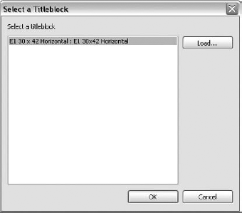
Within the Select a Titleblock dialog box shown in Figure 12.1, select a title block to use for the sheet. If none are available, click the Load button and browse to a title block family file to load.
After choosing a title block, click OK to create the new sheet.
When a sheet view is created, its name is automatically associated with the sheet number and sheet name, which are also properties of the view. You can change this name by changing the parameter values in the properties of the view, by right-clicking the sheet view name in the Project Browser and selecting Rename, or by selecting the sheet and pressing the F2 key, as shown in Figure 12.2. You can also just change the sheet number and name on the title block itself; select the title block and the sheet name and number values will turn blue, which means that you can edit them.
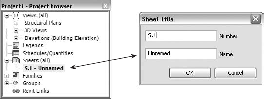
Figure 12.2. Selecting a view and using the right-click shortcut menu or pressing the F2 key is a quick way to number and name sheets.
Sheets have their own category in the Project Browser, which helps keep the sheets organized and easy to work with while documenting the model. Chapter 2 discusses methods of creating browser view types to help sort views so you can easily maintain their organization. Sheets are separate from other views, but you can use these same methods for organizing your sheets. To start the creation of a new browser view type for sheets, go to the View tab
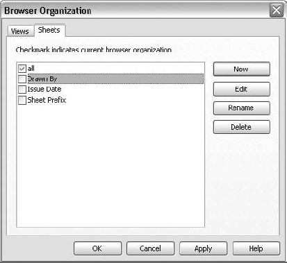
Figure 12.3. Create Project Browser view types for sheets to organize sheets in the Project Browser.
A sheet view, which is basically a drawing sheet, is where you will place your title block for displaying project-specific information with regard to location, owner, and design team as well as sheet numbering, sheet naming, and specific issue information. Like any other object or element in Revit Structure, a title block is a family. In this case it is a component family and can easily be created to match your current title block standards and/or to match another standard your client may require.
Revit Structure has sheets and title blocks. They need each other in order to work properly, and to Revit Structure they pretty much mean the same thing. Since sheets are a system family, all information pertaining to them must be created within the project. Some information and its behavior are hardwired to the Sheets category. We will discuss some of these aspects later in this chapter. Creating the title block for a sheet allows you to display this system information on a sheet along with any other required data that pertains to the project. A title block is a component family, so you can add such information as line work, annotation, images for logos, and Revision Schedules.
The basic procedure for creating a title block is as follows:
Choose the Application menu
The
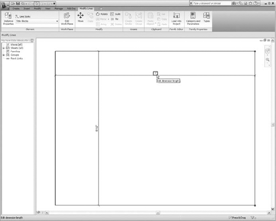
Titleblocksfolder opens, showing a list of available title block family templates. If you do not see these files, browse to theImperial or Metric Templates - Titleblocksfolder and look for them there.Select a size-defined template, or select the
New Size.rftfile and click Open.You will see the extents of a title block, with dimensions indicating its size if you choose the New Size template, as shown in Figure 12.4. You can adjust this line work to the extents of the title block. Once the extents are defined, you can delete the dimensions or turn them off to allow a clear drawing space.
Choose the Category and Parameters tool from the Create tab
Right-click within the drawing area and select View Properties, and you will see that the title block family already displays project parameters and shows how it behaves in a drawing list and Revision Schedule when it is placed into a project.
Save your new title block family, and proceed to adding line work, annotation, logos, and any other information that may be needed.
After you define the size for your title block, you can add content to it such as line work, text, labels that hold project information, images such as company or project logos, and a Revision Schedule. This content can be imported and used from existing CAD drawings or created from scratch. A well-put-together title block will include parametric data that will allow for prompt changes.
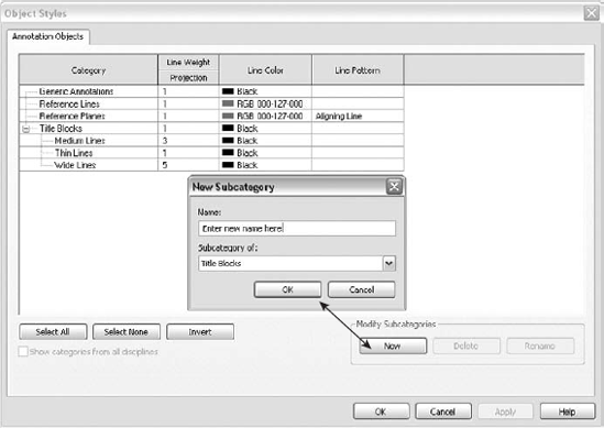
Line work can be added by using the tools in the Create tab on the Ribbon within the family. You can use tools such as Lines, Masking Regions, Filled Regions, and Symbols to help place line work. Lines are defined by a subcategory of the Title Blocks category, which is located in the Annotation Objects tab of the Object Styles dialog box, as shown in Figure 12.5. You can create a new line style by choosing the Manage tab
Make sure that the Subcategory Of value is set to Title Blocks, or the new style will not be available in the Type Selector. Existing 2D CAD data can be imported into the title block family to aid you in the layout of your line work, but keep in mind you won't be able to make it parametric, if that matters to you. You can trace over the top of the imported line work, or you can explode the imported CAD data, which will convert the line work into Revit Structure lines. Creating native line work is relatively simple, so try to avoid leaving unexploded imported objects in the title block family. Convert everything to Revit Structure content so the behavior is a bit more predictable and the family remains free of unnecessary information.
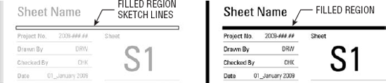
Some borders may have thicker lines to define separations within the title block or to define a boundary. In this case you can use a filled region set to a solid fill rather than using a wide line weight, as shown in Figure 12.6. Revit's lines have round ends, as if they were drawn with an ink pen. The thicker they are, the more obvious the round ends are. This technique will provide the nice "square end" look that many people prefer.
You can easily add text to your title block by using the Annotation tools located in the Create tab on the Ribbon within the family. You can create text styles and use them just as they are used in the project model environment. For each different type of text, you will need to create a new style. New text styles that are created in a title block family will not be available to the project when it is loaded in. This allows you to create the various styles that are needed only for the title block and have the comfort of knowing that they will not be cluttering up your project model. Using the Text tools to place text does not allow them to display the properties of the drawing sheet or any project information. To display this type of information you must use the Label tool. Figure 12.7 shows an example of text and labels being used together in a title block.
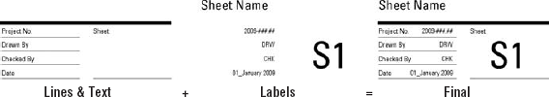
Figure 12.7. Use Text tools where text remains unchanged or changed only once per project, and use Label tools where information is set and changed in the project routinely.
Adding labels to your title block families allows text to automatically adapt to changes that are made to the information that they display. These labels can be used to display information such as Drawn By, Checked By, Sheet Name, Sheet Number, and other parameters. Most of these already exist as project parameters or are built into the title block family. If you need to add additional parameters, you can create them yourself. Chapter 2 discusses adding a project parameter for the contractor's name and having it display in the title block. The same procedure can be applied to other unique parameters you need to create.
To get the intended behavior when creating labels, make sure to take a moment to determine whether they should be Instance or Type parameters. For example, the Project Issue Date that is automatically created in the Project Information dialog box is a Type parameter, and the Sheet Issue Date within the title block family is an Instance parameter. All project information parameters will be Type parameters, which means you change it once and all sheets will show the same value, and the parameters that are already defined in the title block family are Instance parameters. Sheet Number is an Instance parameter because each sheet number is unique.
Another method for making your annotation, as well as other forms of line work, intelligent is to create a Yes/No parameter that allows you to turn the display of those objects on and off. The basic procedure to achieve this is as follows:
While in the title block family select the Types tool from the Family Properties panel located in the Manage tab.
Click Add from the Family Types dialog box to start the creation of a Yes/No Instance parameter.
Fill in the appropriate information, as shown in Figure 12.8. Name it Not for Construction, make it a Yes/No parameter type, group it under Graphics, and make it an Instance parameter.
Once the parameter is created, select the elements within the drawing area that you want to toggle on and off, and select its Instance properties through the Element Properties drop-down located in the Modify "XYZ" contextual tab
In the Instance Properties dialog box select the little rectangular button to the far right of the Visible parameter.
Select the Not for Construction parameter from the Associate Family Parameter dialog box, and click OK to return to the Instance Properties dialog box.
Observe the equal sign that now displays on the little rectangular button to the right of the parameter. This indicates that this element property is linked to the Yes/No parameter. Figure 12.9 shows the process involved to connect the text to the Yes/No parameter.
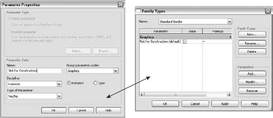
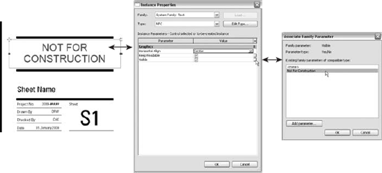
Figure 12.9. Create a Yes/No parameter to help control the display of elements in a title block family.
Depending on how you want the Yes/No parameter to behave, you can make it an Instance or a Type parameter. If you designate it a Type parameter, you could have two different title block types: one named For Construction and the other Not for Construction; then you can switch them as the project reaches the construction stage. If you designate it an Instance parameter, each instance of the title block family could have its own unique setting.
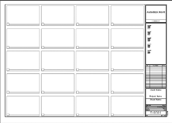
Another good use for a Yes/No parameter in a title block family is in creating a standard detail "grid" layout, as shown in Figure 12.10. This grid can be set to display as an Instance parameter of the title block family to be displayed and used while you are placing and arranging views on a sheet. After you have finished placing the views, you can toggle off the detail grid so it will not plot. Revit Structure will help align views to each other, but this grid can help prevent users from trying to place too many views on a sheet as well as aid in complying with sheet layout standards, like the NCS/UDS (National Cad Standard/Uniform Drawing Standard).
Revit Structure allows you to import several different image formats into your title block families. You can see a list of these formats as well as the first step in importing an image by choosing the Insert tab

Figure 12.11. You can adjust the size of an image by selecting it and then dragging the grips at its corners; use Lock Proportions on the Options bar to maintain its aspect ratio.
You'll have better luck using images in Revit Structure for logos that contain fancy font display rather than using a complex filled region with line work and adjacent text, custom fonts, or imported 2D CAD graphics. If images are not created for these complex logos, you can perform screen captures with the Windows Ctrl+Alt+Print Screen keys and then paste the screen capture into editing software to crop as needed. This may not always produce a high-quality graphic, however, so you may need to use other image-capturing or printing tools.
Chapter 11 discusses in depth how to create various schedules for quantities and for displaying structural information for documentation. In this section we will discuss the things that are different in Revision Schedules from the schedules that are created within the project environment.
Revision Schedules can be created only while in a title block family. Therefore this feature will not be available in a project environment. Revision Schedules behave and are created pretty much the same way as other schedules created in the project environment. When Revision Schedules exist in a project, they populate with revision information as it is created and added to the project. Adding this revision information is discussed in the section "Keeping Track of Revisions" later on in this chapter.
The basic procedure for creating a Revision Schedule is as follows:
While in a title block family choose the View tab
By default, parameters that are available for schedule fields are already present, as shown in Figure 12.12. At this point you can click OK, and a schedule will be created.
Observe the available tabs at the top of the Revision Properties dialog box shown in Figure 12.12. These tabs all have the same look and feel that other schedules have. The only difference is that Revision Schedules do not have a Filter tab. Therefore, you will not be able to use filters when creating these types of schedules.
Once the schedule is created, it will appear in the Project Browser, as shown in Figure 12.13.
There are a couple of ways to get the Revision Schedule onto the title block sheet. One way is to select and drag the Revision Schedule in the Project Browser over to the hyphen that is located under Sheets (all). When you release the mouse button, the drawing area will switch to the view that contains the title block line work; there you can place the Revision Schedule just as you would any other schedule. Another way is to already have the title block open for editing and then drag the Revision Schedule from the Project Browser onto the sheet.
Adjust the appearance of your schedule in its Element Properties dialog box, and adjust its size to fit within your title block by selecting the Revision Schedule while in your title block sheet view and dragging the shape handle control as required. To access the Element properties of the Revision Schedule, you can select the schedule on the sheet, right-click it, and choose Edit Schedule from the shortcut menu. This switches you to the schedule view where you right-click and choose View Properties from the shortcut menu. An alternative method is to select the schedule name in the Project Browser, right-click it, and choose Properties from the shortcut menu.
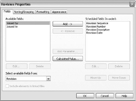
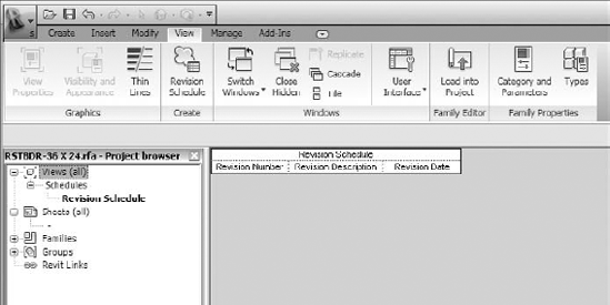
Figure 12.13. Revision Schedules show up in the Project Browser, where you can drag them onto the title block sheet for use in your project.
Earlier we said that creating a Revision Schedule is pretty much the same as creating other schedules within a project. Let's discuss those aspects that are different by looking at the Appearance tab, shown in Figure 12.14. You can find this tab by going to the properties of the Revision Schedule.
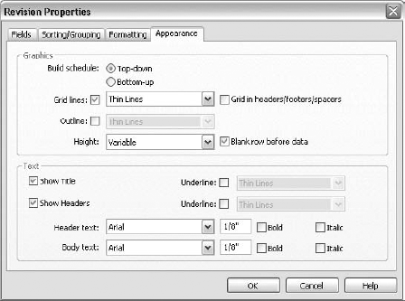
Within the Appearance tab shown in Figure 12.14 you will find fields that are available only for Revision Schedules. These appearance settings allow you to build the schedule to autopopulate from the top down or from the bottom up as well as have a variable or user-defined height. This information will display for other schedule types but will be grayed out and unavailable.
The first field that will become available is Build Schedule: Top-down or Bottom-up. This allows you to define the schedule to display schedule information from the top down, like any other schedule that is created in Revit Structure. Selecting Bottom-up allows you to create Revision Schedules that list the scheduled information starting from the bottom, as some firms prefer. Figure 12.15 shows the result of using these features.
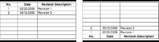
Figure 12.15 also shows the schedules with a user-defined height that allows them to show only a fixed number of rows so they can be placed in a defined area inside the title block.
The second field that will become available is the Height field, which allows you to define the schedule height as Variable or as User Defined. Setting the Height value to a variable height allows the schedule to display as many horizontal rows as required. The height of the schedule grows as each new revision is added to a sheet. With this setting your schedule has a potential to grow to an undesirable height or length that might eventually conflict with other annotation and/or line work in your title block.
When your title block requires a limited space to be available for revision information, you should set the Height value to User Defined. This allows you to adjust the overall height of the Revision Schedule while inside the title block family. Figure 12.16 shows a selected schedule with its Height set to User Defined.
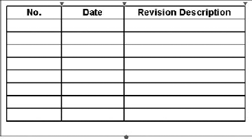
Figure 12.16. When Height is set to User Defined, you can adjust the fixed height by dragging the grip control.
Schedules that have the Height value set to User Defined can display only a certain number of revisions, depending on the number of rows available to display the revision information. As the schedule fills up, the earlier/oldest revisions get pushed out to make room for the new ones. If a schedule is created to show only five rows of revision information and it is filled with five revisions, revision 1 will be removed from the schedule to make room for revision 6. When revision 7 is added, revision 2 is removed.
Revision Schedules can be created to accommodate many different requirements. The best way to see all the various options is to create a new title block, add a Revision Schedule, and experiment with all of the different options. Load the title block into your project, and add revisions to the sheets to see how each change to the various settings in the Sorting/Grouping, Formatting, and Appearance tabs in the Revision Schedule properties behaves. Adding revisions to sheets will be discussed shortly.
Sheets are one of the ways to disperse information about your project so others can access it. Typically these sheets will eventually be plotted. Beyond adding a title block to your sheets, you can add any view that was created that displays bits and pieces of the model in a schedule, section, or plan form. Placing these views onto sheets is really as simple as dragging them from the Project Browser and dropping them onto the sheet view. Once they are placed on a sheet, additional parameters become available as properties to the view. Some of these parameters are unique to the view type that is being placed, and others like the Sheet Number and Detail Number are part of almost all types of views.
Revit Structure's use of view titles helps keep your views organized onto sheets. View titles can display information about the view so those using the sheets can easily find the information they are looking for.
Sometimes thinking outside the box will allow you to take advantage of Revit Structure's views and pull information from the model. Creating a key plan from the model is an example. As the model changes, your key plan changes also. Adding more line work or text on the sheet as an overlay to the views that are placed on it allows you to provide additional information that is specific to the sheet or to combine two separate details into one. You can even overlap plan or elevation views to create nonexistent composite views.
Different view types are used depending on what type of information you are showing about the model and how you want to show it. These view types are system families. Learning the parameters that appear when these views are placed onto a sheet and the different behavior each one can take on will help you produce great-looking documents that are easy to understand and work with.
There are several ways that you can add views onto a sheet. The various methods for adding any view onto a sheet are as follows:
- Method 1
With the sheet view already open, drag and drop the view from the Project Browser onto the sheet.
- Method 2
Drag and drop the view from the Project Browser onto the sheet name in the Project Browser. This automatically opens up the sheet view to allow you to place the view.
- Method 3
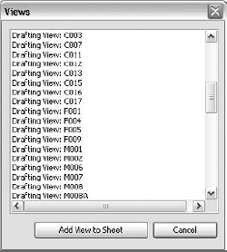
Within the Project Browser, right-click the sheet onto which you will be placing a view, and select Add View. This action automatically opens to the selected sheet view and displays the Views dialog box shown in Figure 12.17. This dialog box shows a list of views that are not yet placed onto any sheet. Choosing a view and clicking the Add View to Sheet button allows you to place the selected view onto the sheet. By using this method you can avoid having to search through other views that are already placed on sheets.
- Method 4
With the sheet view already open, go to the View tab on the Ribbon and select the View tool from the Sheet Composition panel. The same dialog box shown in Method 3 appears, where you can select from a list of views. The active view must be a sheet view, or the View tool will be grayed out.
As you can see, there are several methods you can use to place views onto a sheet. It is up to you to determine which one works best with your working habits. Once views are placed onto sheets, you can take advantage of those parameters that become available or those that have information available for display while they are on the sheets.
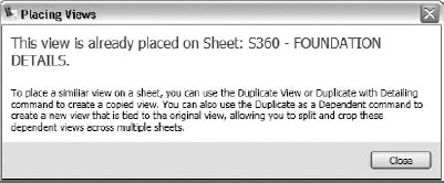
Only One Sheet Please
Revit Structure does a great job of keeping track of what views are on sheets, the sheet number they are on, and their detail number on the sheet. This helps keep your documents coordinated at all times. For this reason Revit Structure allows some views to be placed onto a sheet only once. If the same view were on a sheet twice, it would be tough to keep track of which sheet it needed to be referenced to. When a user attempts to place one of these views onto a sheet that is already on a sheet, the warning dialog box shown here will appear.
Adding views to sheets adds another level of organization to your project. When you expand any of the sheet views in the Project Browser, every view that is placed on that particular sheet is listed, as shown in Figure 12.18. Once you expand the list, you can select any of the views and right-click it to access its properties, rename it, remove it from the sheet, or open it to edit.
You also have the ability to access the individual views that are placed on a sheet by activating a view and working through the sheet. Once you are further along in your project, this can be an efficient way to access the views that you are using for documenting the model. Figure 12.19 shows that you can right-click on any view that is on a sheet to select Activate View from the shortcut menu. This is no different from opening up the view from the Project Browser except you are seeing it displayed on your sheet with other views as well as working in the view.
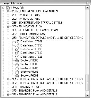
Figure 12.18. Use the sheet views in the Project Browser to quickly access views that are placed on sheets.
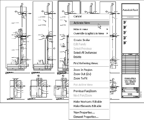
Figure 12.19. You can work on views through your sheets by right-clicking a view and selecting Activate View.
When you have finished working in the view, right-click again anywhere on the sheet and select Deactivate View from the shortcut menu. This can be an excellent method for reviewing and editing your documents while avoiding plotting the sheets or if you are picking up minor red lines that were made on a hard copy or a design review markup.
Understanding the behavior of the various views as they are placed on sheets and learning which parameters are associated with each are definitely something that you want to master. Grasping things like the various view properties, view title manipulation, and key plan strategies will give you the edge you need to use every bit of information that is available to you to help create a good-looking set of documents that will complement your modeling efforts.
These view types have all the additional properties applied to them when they are placed onto a sheet. If for any reason some of them need to be rotated on a sheet, you can rotate them clockwise or counterclockwise by using the Options bar and the Rotate on Sheet drop-down list at the time of placement or after the view has been placed. The value of the Title on Sheet parameter can be filled in to override the view name that is displayed in the view title.
Other parameters that become available for these view types are as follows:
- Detail Number
This contains the value that the view is given as its number on the sheet. The user can change this value, but no number can exist twice on the same sheet. When the first view is placed, Revit Structure gives it a value of 1. As additional views are placed on the sheet, Revit Structure automatically takes the next number in line or the lowest number not used.
- Sheet Number
This contains the value of the sheet number that the view is placed on. This value updates as a view is moved onto a different sheet or a sheet number changes.
- Sheet Name
This contains the value of the sheet name that the view is placed on. This value updates as a view is moved onto a different sheet or a sheet name changes.
- Referencing Sheet
This contains the value of the sheet number that the view is referenced from. If a view is referenced from more than one sheet, then the sheet number that referenced the view first will be displayed as the value.
- Referencing Detail
This contains the value of the detail number that the view is referenced from. If a view is referenced from more than one detail number, then the view that referenced the view first will be displayed as the value.
The parameters mentioned here can be used to display information in the view titles to aid in the layout and control of referencing information while you are documenting the model. Legends, schedules, and Graphical Column Schedules have behaviors that are much different from those of other views when they are placed on sheets.
Legends are somewhat a combination of a detail view and a drafting view as to what is displayed inside of them, but they resemble the properties of schedules and Graphical Column Schedules when they are placed on sheets. They are like drafting views to the extent that they do not allow you to display geometric information directly from the model and they do not have a view range, but like other views they can have annotations, symbols, region fills, detail lines, and the like added to them. They are similar to detail views in that they do allow you to display model information, except that information is not graphically from the model. You can display parametric information about the various family types that exist throughout a project. A more in-depth explanation on legends and keynote legends can be found in Chapters 9 and 11.
Legends cannot be rotated when they are placed on a sheet, and they are not referenced to sheets. Since they are not referenced to sheets, they do not have the additional parameter to keep track of what sheet number they are on or what number they are assigned when placed on a sheet. They can be placed onto multiple sheets but cannot be placed multiple times on the same sheet. Revit Structure does not support multiple instances of a legend on the same sheet. You can override the display of a legend's view name in a view title by filling in the value for the Title on Sheet parameter.
Chapter 11 discusses how to create and work with schedules prior to them getting placed onto a sheet. Once a schedule is placed onto a sheet, it can be rotated clockwise or counterclockwise 90 degrees by selecting the schedule and using the Rotate on Sheet drop-down list on the Options bar. A schedule can be placed onto the same sheet multiple times; therefore it will not have a Detail Number parameter assigned to it when it is placed on a sheet, nor will it have any other parameters. Selecting the schedule while it is on a sheet and choosing Element Properties will only bring up a blank properties box.
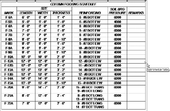
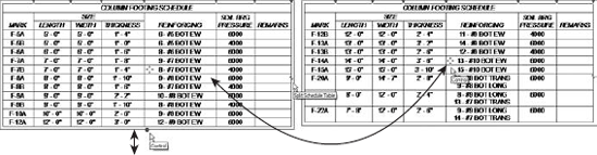
Once a schedule is placed on a sheet, you can adjust the width of the columns by dragging the shape handle controls that display when the schedule is selected. You can do this only after the schedule is placed on a sheet. If for any reason a larger schedule needs to be split into separate chunks to fit on a sheet, you can easily do so by selecting the schedule while it is on the sheet and clicking the Split Schedule Table "break" symbol at the right of the schedule. Each click will break the schedule in equal parts. Figure 12.20 shows a single schedule that is selected and about to be split into two segments.
Figure 12.21 shows the same schedule split into two segments. Dragging the grip control (filled dot at the bottom of the first column) and moving it up or down will move rows from one segment to the other. Dragging the move control (four-way-arrow symbol) back onto the adjacent segment will join the schedules back together. Clicking the break symbol again will split the schedule into additional segments.
Graphical Column Schedules are also schedules, but they are assembled and automated much differently by Revit Structure. They are really a "hyper schedule" of little "views" of columns since they have a detail-level control for their graphical appearance, much different from a standard schedule with rows of data. They too can be split into multiple segments but take a much different approach than just clicking a break symbol.
Chapter 4 discusses in great depth how to create the Graphical Column Schedule (GCS) as well as several of its properties. The GCS has a behavior that it takes on only when it is placed onto a sheet. The only way to access this information is to select the GCS that is on the sheet and choose its Element properties. Accessing the properties by first selecting the view name in the Project Browser will not display this information. Figure 12.22 shows the additional segment information that is displayed under the Extents group of the Element properties.
The GCS does not have a Detail Number parameter when it is placed onto a sheet, so it can be placed onto different sheets multiple times but not twice onto the same sheet. Revit Structure does not support multiple instances of a GCS on the same sheet. In the properties shown in Figure 12.22, the GCS has a total of four segments. The Segments Start in Viewport and Segments in Viewport parameters are Instance parameters for each GCS that is placed on a sheet. This means each parameter can have its own value and not affect the other one but still exist as one GCS. In some cases all of the segments may not fit onto one sheet, so these values will have to be adjusted accordingly.
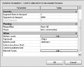
Figure 12.22. Place segments of a Graphical Column Schedule onto multiple sheets by adjusting the segment parameters in its properties.
With the help of Chapter 4, create a five-segment GCS to use while reviewing the following basic procedure for distributing a GCS segments onto multiple sheets.
Create two sheets. The first one will contain three segments, and the second one will contain two segments of a five-segment GCS.
Place the five-segment GCS onto each sheet.
Make the first sheet view active, and review the GCS properties by selecting the GCS on the sheet and then accessing its properties from the Ribbon or by right-clicking the sheet and choosing Element Properties from the short-cut menu.
In the Extents group of its Instance Properties dialog box, change the value of Segments in Viewport to 3. This will display segments 1 through 3 for this instance of the GCS. Click OK to see the results.
Make the second sheet view active, and review the GCS properties by selecting the GCS on the sheet and then accessing its properties from the Ribbon or by right-clicking the sheet and choosing Element Properties from the short-cut menu.
In the Extents group of its properties change the value of Segments Start in Viewport to 4 and the value of Segments in Viewport to 5. This will display segments 4 through 5 for this instance of the GCS. Click OK to see the results.
Note that if you set the initial extents of the viewport values while the GCS is placed on only one sheet, Revit Structure will automatically display the remainder of the segments when the next instance of the GCS is placed on another sheet.
As you can see, these parameters allow you to adjust each instance of the GCS so you can display whatever segments you want to display as the GCS is placed on a sheet. Normally the view title displays the view name when a GCS is first placed on a sheet. This view name can be overridden by filling in a value for the Title on Sheet parameter. If a value exists for this parameter, the view name that is displayed in the view title by default is replaced with it. The GCS has a parameter to display its own title at the top of the schedule, so you may prefer that the view title be set to not display.
When views are placed on sheets, view titles are used to display information about those views. These view titles are linked directly to the view and pull information directly from the properties of the view. As properties of the view change, the information that is displayed in the view title automatically changes with it.
View titles can have different types assigned to them to allow you to display different information about a view throughout a sheet. Some views may require only a title, and some may not require anything. For each required display you create a new view title type. Three view title types exist in the Structural Analysis-Default.rte template that is provided by the Revit Structure installation:
No Title
Title Only
Title w Line
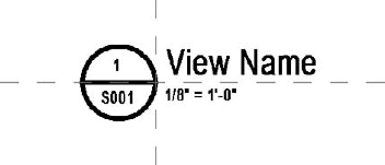
These view titles are set to display the scale, the view name or title on sheet, and the detail number inside a circle. You can create additional view title types by duplicating an existing one and changing its properties as needed. If you want to display new geometry and/or parameters, then you will have to create a new view title family. For instance, some companies prefer to add the sheet number as part of their view titles.
Exercise: Creating a New View Title
To create a new view title you can start from an existing family that is already part of the Revit Structure installation, or you can start from scratch by using a View Title template. Revit Structure already has a family created similar to the one we are creating, except the circle element is larger. You can locate this family by browsing to the Imperial Library - Annotations folder.
For this exercise we will start from a View Title template so you can see the steps involved for creating one from scratch. To start we will create the look of the view title in a family and then load it into the project, where we will make it a View Title type.
Creating a New View Title Family
Choose the Application menu
Browse to the
View Title.rtefamily template located in theImperial Templates - Annotationsfolder (orMetric Templates).Choose the Category and Parameters tool from the Create tab
Read the red block of note text that was preloaded in the template, and then delete it and the "dummy line" below it, as instructed.
Add line work and labels as shown in example graphic by using the tools in the Create tab on the Ribbon. The default Object Style for View Title in the template has a pen weight of 1. Once the family is loaded into your project, you can globally specify in the Object Styles dialog box of your project a line with that fits your standards for display. The image below has the line weight enhanced for print.
For the circle and line geometry, use the Line tool from the Detail panel along with various types of lines, circles, or arcs that can be found in the Draw/Pick Gallery on the Place Lines contextual tab that appears after choosing the Line tool.
To place the parameter information for the view data that will be part of the view title, click the Label tool located in the Create tab
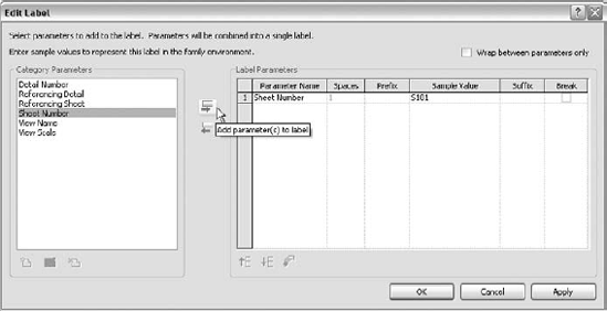
To add a parameter, choose it in the Category Parameters area at the left, and click the Add Parameter(s) to Label button. This is the button with the green arrow pointing to the right. Selecting this button places the parameter in the Label Parameters area to the right. Click OK to apply the parameter and close the dialog box. Tip: You can also just double-click the parameter name to shift it over as well.
Once the label is placed in the drawing area, drag it into its final position. Check to make sure its Justification properties are set properly, and edit its Element properties if necessary.
Repeat steps 7 through 9 to add the other labels to the view title.
Go to the Visibility/Graphic Overrides dialog box and turn off reference planes and dimensions so the thumbnail is easier to see when users load the family.
Save the family, naming it whatever you wish. After saving, load it into your project.
Creating a New View Title Type
The only way to edit or create a viewport type and assign your new view title to it is to select a viewport. If you haven't placed any views on a sheet, you'll need to do that first.
In your project select a view title or view that is displayed on a sheet, and click the Element Properties drop-down to access its Type properties, found on the Modify Viewports tab of the Elements panel of the Ribbon.
Choose Duplicate.
In the Name dialog box type a name and click OK.
Change the Title parameter value to match the view title family name that you created previously. Select the family name from the Title drop-down list, which won't be visible until you click in the field in the Value column.
Make adjustments, if needed, to other graphic parameters such as Line Weight, Color, Line Pattern, and the visibility of its title or extension line.
Click OK in the Type Properties dialog box.
Observe the new view title type, and check to see that its appearance is as you intended.
View titles allow you to control the display of the various components that compose them in a couple of places. To control the line weight, line color, and line pattern of the extension line, you will need to go to the Type properties of the view title, as shown in Figure 12.23.
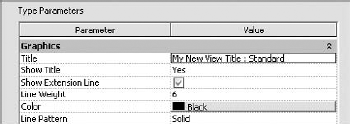
Figure 12.23. Change the display of a view title extension line by going to the properties of the view type.
To control the line weight of the annotation symbol that is created inside the family, you will need to choose the Manage tab
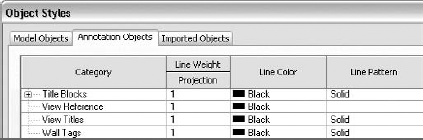
Within the Annotation Objects tab of the Object Styles dialog box, go to the category View Titles. Here you can change the line weight, line color, and line pattern.
In the past, in the 2D CAD environment, key plans probably consisted of line work that made up the perimeter shape of a building, some annotation for area delineation, and hatching to denote which area is shown on the sheet. There were probably other reasons for key plans even though you were not referencing zones or areas of a large-footprint building. You can still use those same strategies in Revit Structure, or you can go one step further and use modeled geometry to produce your key plans. Using modeled geometry for key plans will help keep them up to date with the current design of the building. It may even help you use key plans more often to aid in producing clearer documentation of your model.
There are several strategies for creating key plans, and they are explained in the following sections. Each strategy has pros and cons. Strategies such as the use of an annotation symbol family or images/screen captures can be embedded in title block families. Reduced structural plans and legends require them to be created directly into your project, and they are placed as views on sheets. You will need to choose which strategies will work for you as an office standard or on a project-by-project basis.
Using a reduced structural plan is probably the best strategy to allow the key plan to update as the model updates. The idea is that separate plan views are created at each level and then placed on sheets. The following procedure lists the necessary steps to quickly create key plans by using structural plans.
Create a structural plan of a level by creating a new one or duplicating an existing one. Name it accordingly.
Change the scale to a custom scale that allows a small key plan to be placed in a convenient and consistent location on a sheet.
In the Visibility/Graphic Overrides dialog box of the view, turn off the display of all model and annotation categories by selecting all and toggling their visibility off. Only a few categories will be turned back on. With everything off it is much easier to turn on the visibility of only those model categories that you want to be displayed.
Turn on the visibility of only those categories that you want to be displayed. Usually Walls, Floors, Roofs, and sometimes Grids will be enough categories to give you the display of the building footprint. Categories can be toggled on or off depending on how you want the key plan to display.
Override the line weight of the categories that are on to accommodate the reduced scale.
If needed, hide individual elements in the view or override their display individually.
Once everything is set the way you want, create a view template and name it Key Plan.
Create additional key plans for other levels, and apply the view template Key Plan to them.
Add additional line work, annotation, and region fills as required.
Drag each one to its appropriate sheet.
When using this method, you will need to create separate key plans for each zone or area of the plan you will be denoting. Structural plans can be placed on only one sheet before they have to be duplicated. The example shown in Figure 12.25 is a key plan for Zone 2 first-floor framing plan. We created this by following the procedure just outlined. Each zone is its own separate key plan with annotation, line work, and region fills specific to each view.
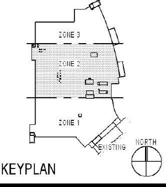
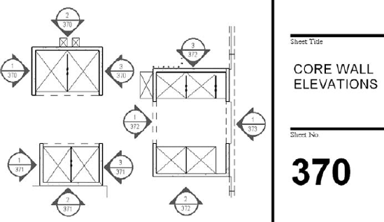
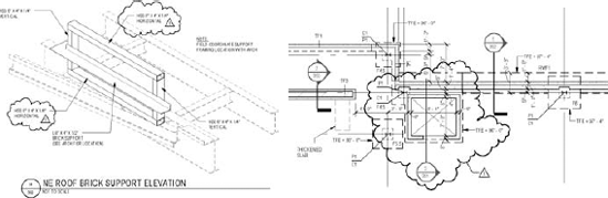
Figure 12.26 shows a similar example of a key plan displaying the parametric section cuts to reference the location of shear wall elevations that were used to document construction joints, reinforcing, and embed plate locations. Everything automatically updates in the key plan as the model changes or section references change locations.
Legends can also be used to create key plans. If a key plan is already created in another CAD system, the line work can be imported into the legend to be used directly or to be traced over the top of. Since legends can be placed on more than one sheet, there is potential to reduce the number of key plans you have to create. If it is not critical to follow the exact footprint, the same Zone 1, Zone 2, or Zone 3 legend could be placed on levels 1 through 10. In this scenario only three legends would have to be created. Legends can be used for building footprints just like the other methods we mention, but as you see, Figure 12.27 illustrates the use of a legend as a key to show what the information that is being displayed in a Graphical Column Schedule relates to. Using a legend as a key in this instance allows you to have one key that can be placed on multiple sheets.
Making use of annotation symbols can be a clever little way to go about creating a key plan. This allows you to create a key plan family that can be placed as a symbol onto each sheet. Line work can be added just as you would in any other example shown here. If a key plan is required to show different shades to denote zones or areas, you can add a Yes/No parameter to control the display of the hatching or filled region. An example of how to create a Yes/No parameter can be found in "Making Your Annotation Intelligent" earlier in this chapter.
The basic procedure for starting a new annotation symbol family is as follows:
Choose the Application menu
Browse to the
Imperial TemplateAnnotationsfolder, and select theGeneric Annotation.rfttemplate.A symbol used as a key plan can be categorized as Generic Annotations. You can verify this setting by choosing the Category and Parameters tool from the Create tab
If the example shown in Figure 12.25 for the reduced plan method was created by using an annotation symbol, you could create the line work by placing new line work or importing existing line work. You could create a reduced plan view by using elements from the 3D model. The reduced plan view could be exported to AutoCAD to create 2D line work. This AutoCAD file could then be imported into the annotation symbol family. For the separate zones, region fills could be created and placed on Yes/No parameters. Three parameters would be created for this (Zone 1, Zone 2, and Zone 3). Each one would be set accordingly to create its own type, so depending on where the key plan was placed, it could display Key Plan Symbol Type Zone 1, Zone 2, or Zone 3.
Images and screen captures can be used for key plans as well. Screen captures or images can be developed from existing key plans and placed into other views previously mentioned. Additional annotation, line work, and region fills can be used in conjunction with these images to create a look that suits your needs.
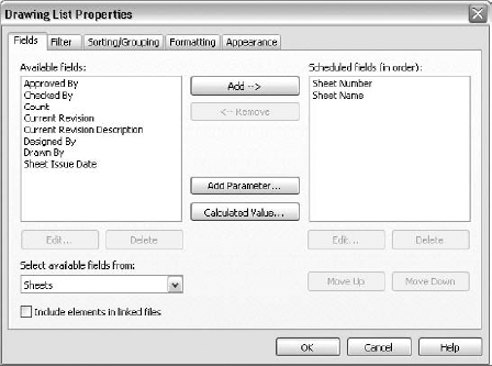
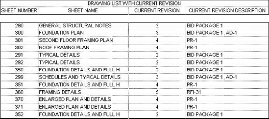
Revit Structure automatically keeps track of sheets, and information such as sheet name and number can be displayed in a schedule-like format called a drawing list, more commonly known as a sheet index. As shown in Figure 12.28, creating a sheet index is similar to creating any other schedule in Revit Structure in that you can add fields, create filters, provide sorting or grouping, adjust the formatting, and set the appearance.
You can create and manipulate drawing lists using the same methods as for the schedules discussed in Chapter 11, except that when you create a drawing list you use a specific Drawing List tool that locks the category to display only information that is part of the Drawing Sheet category.
The basic procedure for creating a sheet index is as follows:
Choose the View tab
Within the Fields tab of the Drawing List Properties dialog box, add any of the available fields on the left-hand side of the dialog box to the scheduled fields on the right-hand side by selecting the field and clicking Add.
To include sheets from another Revit project file that is linked to your project, check the option Include Elements in Linked Files.
Reorder the scheduled fields if needed by selecting a field and clicking the Move Up or Move Down button as required.
Open the Filter and Sorting/Grouping tabs to create any filters and sorting or grouping rules that may be needed.
Open the Formatting tab to adjust the formatting of the sheet index headings and the alignment of the scheduled text.
Open the Appearance tab to set the appearance of the graphics and text.
Click OK to finish the drawing list.
Drawing lists can also be useful in helping to keep track of title block information. Viewing or populating this type of information can be easily be done through a schedule form rather than by individually viewing sheets and their properties. Information that can be added to a traditional sheet index to be used in checking for title block coordination includes the following:
Checked By
Designed By
Drawn By
Approved By
Sheet Issued Date
Current Revision
Current Revision Description
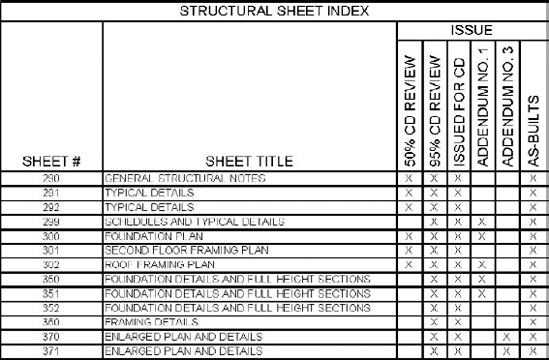
Sometimes you may need to create a much more advanced sheet index for larger projects or for those that have numerous issues. Keeping track of these issues can otherwise be a nightmare. Using Revit Structure to help automate some of this work will help eliminate confusion as to which sheets were issued when and for what reason. Figure 12.29 shows a more advanced drawing list that keeps track of the sheets as well as what they were issued for.
You can create a more advanced sheet index by adding additional project parameters that are linked to the Sheets category. Once these parameters are added, they will become available to be added to the scheduled fields. Within the Formatting tab, the Heading Orientation setting for the Issue field's headers is assigned to Vertical. When sheets are issued, the value of the Issue parameter in the properties of the sheet is populated with an X or any other character or symbol that you choose. Once the sheet index is placed on a sheet, you can adjust the columns as required.
The basic procedure for creating these additional parameters is as follows:
Go to the properties of the drawing list, and in the Fields tab, click Add Parameter. Adding this parameter within the properties of the schedule will automatically select the appropriate category for the parameter.
Select Project Parameter for Parameter Type.
Give it a name of ISSUE_01_50% CD REVIEW.
Select Text for the Type of Parameter.
Select a group to place the parameter in that makes sense to you.
Click OK.
Repeat steps 1 through 6 for as many parameters as you want to add.
Once the new parameters are created, they are listed under Scheduled Fields.
You can create a sheet index that also keeps track of the issue date information with the addition of a drafting view or a legend. This method requires that the drafting view or legend be manually coordinated with the drawing list. Figure 12.30 shows a sheet index that has been created with this method.
The upper portion of the sheet index shown in Figure 12.30 is a drawing list, with additional parameters added to the Sheets category. Symbol characters have been added to indicate the values of these parameters depending on how the sheets are being issued. To add a symbol character you must insert the symbol via the Windows Character Map application and copy and paste it into the text field within Revit Structure.
The lower portion of the sheet index is a drafting view, with line work and text added to match the look of the sheet index. This portion has to be manually coordinated with what is shown in the sheet index above it each time you issue it. This method works well because you can display a much lengthier issue name without the sheet index getting too large, and you can also keep track of the issue dates as well as how the sheets were issued.
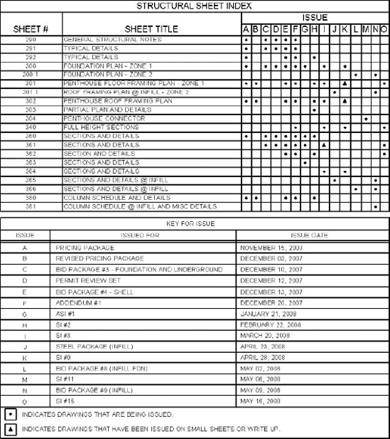
Figure 12.30. A sheet index created with additional parameters and a drafting view to help support the issue information
Current Revision on a Sheet
When creating a drawing list you can also utilize such parameters as Current Revision and Current Revision Description. This is a new feature in Revit Structure 2010. Creating a Drawing List Schedule to show these parameters is a great way to display the most recent issue or revisions to a sheet. This can really come into play for projects with several sheets.
Learning to create a sheet index to this extent will help you to keep your sheets in sync with the revisions that you are adding to them. It may be necessary to manually keep track of these issues and revision names adjacent to a sheet index in a "Key For Issue" schedule via a Drafting View as we have shown earlier, but you will be able to use Revit Structure's revision tools to help automate the process on a sheet-by-sheet basis as well as automate the control of the information that gets displayed in a Revision Schedule.
Keeping track of revisions so others can clearly see what has changed with the model or with the documentation is another task that Revit Structure does well. Similarly to how views on sheets are repeatedly being coordinated with the sheet they are on and where they are referenced from, revisions know what sheet they are placed on, keep track of whether they are issued or not, as well as hold other valuable information about the changes being made.
When you get started your project template should already have one revision defined and waiting for the day you need it. Revit Structure uses a Sheet Issues/Revision dialog box to define all of a project's issues/revisions. In practice you'll probably find that having a single revision waiting for you in your template allows you to start off creating revision clouds to identify where your first round of changes occur. Then you can visit the Sheet Issues/Revision dialog box to deal with new changes. This section is organized that way. We'll discuss what you do with revisions and then wrap up with an in-depth explanation of all the elements that support this feature.
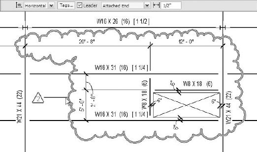
A typical revision consists of a cloud that displays all the information that pertains to a particular revision that is defined and stored in the Sheet Issues/Revision dialog box. We will ease into discussing this dialog box as we continue on. The cloud, which is a graphical mechanism to define where a revision affects the drawing, is placed around the area of change to indicate where the change is made. A tag that displays information from the cloud properties is placed alongside the cloud. When Revit Structure detects that a revision is on a sheet and a Revision Schedule is present in the title block, it displays and tracks the revision information for that sheet. Figure 12.31 shows revisions as they would be used on a project.
The basic procedure for placing and tagging a revision is described in the following sections.
Placing clouds in Revit Structure is very similar to how you may have done it in a prior 2D/3D CAD environment. You may have used an inserted block or a tool that allowed you to sketch the extents of the cloud. Revit Structure's Revision Cloud tool allows you to sketch the boundary of the revision cloud directly in the views where the revisions occur or directly on the sheet. To place a revision cloud, follow these steps:
Choose the Annotate tab
Placing a cloud will put you into Sketch mode, where you sketch the extents of the cloud by using the Line tool from the contextual tab that appears.
Clouds are sketched by consecutively clicking placement points to form a boundary. After you place your first point, each subsequent sketch point clicked creates a pair of arcs—the smaller is about a third of the size of larger arc—to represent a "sketchy" cloud shape. Pressing the spacebar while sketching an arc segment flips the orientation of the arcs. The size of the arcs increases or decreases according to the distance between the points you pick.
When the sketch is complete, click Finish Cloud from the Ribbon. A revision cloud does not have to be closed like other sketch-based elements in Revit, though most clouds, in practice, probably ought to be.
One of the best features of placing revision clouds in Revit Structure is that revision clouds are assigned to defined revisions. These clouds allow Revit Structure to keep track of those views that contain them and are on a particular sheet. Revit Structure does not know where the actual revision has occurred, but it knows that you placed a revision cloud in a view by tracking its existence. You can tag revision clouds just like other elements in Revit Structure to display their properties or denote them as a symbol that links to a Revision Schedule, where additional information can be displayed.
No Revision Cloud Required
Revit Structure automatically populates a Revision Schedule with revision cloud information when it detects a revision being placed on a sheet and the presence of a revision in a view when the view is placed on the sheet. Sometimes you may want to record information about a revision within a title block that does not require a revision cloud. For example, you may want to record information about a 50 percent review set, issued for DD or issued for CD. Whatever it may be, it might not require a revision cloud.
You can create a revision on a sheet without requiring a cloud by right-clicking a sheet in the Project Browser and choosing Properties. In the properties of the sheet click the Revisions on Sheet parameter located under the Identity Data group, and click the Edit button. The following illustration shows the Revisions on Sheet dialog box, where you can choose to record a revision on a sheet without having to place a revision cloud.
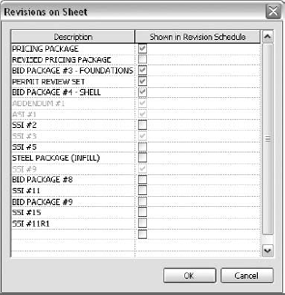
All the revisions in the project will display, and those that are already on sheets from the placement of a revision cloud will be grayed out. Checking the Shown in Revision Schedule field populates the schedule with that particular revision without having to place a revision cloud.
If multiple sheets are selected, this parameter will not be available to edit. You can select and set only one sheet at a time to display revision information.
Before you can place a tag to reference a revision, you will need to place a revision cloud. The tag is a label that can be defined by the user to display properties about the revision cloud. To tag a revision cloud, follow these steps:
Choose the Annotate tab
Use the Options bar to adjust placement properties prior to placement.
Select a revision cloud element to be tagged.
The Options bar shown in Figure 12.32 offers several options that you can set prior to tagging a revision cloud. The Options bar will display some settings when you select an existing tag as well.
Reading from left to right, the revision-tagging Options bar in Figure 12.32 allows you to do the following:
Select Horizontal or Vertical to predetermine the orientation of the tag.
Click the Tags button to select which loaded tag to use. If the desired tag is not loaded, you can click Load to find it and load it now.
Choose to place a tag with or without a leader.
Choose to have the end of the leader attached to the cloud by setting it to Attached End or to a location of your choice by setting it to Free End.
Set the initial leader length dimension from the end of the leader back to the tag. After the tag is placed, you can move it along with the leader to any location you want.
You use Revit Structure's Object Styles dialog box to set the appearance of revision clouds and tags that may be used to label them. These settings can be found by choosing the Manage tab
You may need to assign revision clouds that are already placed throughout the model to a different revision. Revit assigns the latest revision/issue to a revision cloud when you click Finish Cloud. If a revision cloud is assigned to the wrong revision, you can change it. If revision clouds are tagged, they will automatically reflect the new revision information. You can do this by selecting the revision cloud(s) and choosing Element Properties or by going to the Options bar. Figure 12.33 shows how these methods will let you choose which revision type the cloud should be assigned to.
If you need to move several revision clouds to a different revision, you may need to individually select each revision cloud or select them all by using a window selection and filter the selection to select only the revision clouds. The Select All Instances method is not available when working with revision clouds in Revit Structure.
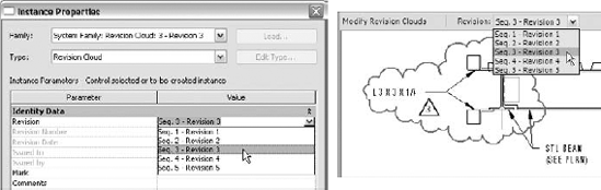
Figure 12.33. Change a revision cloud's type by going to its properties or the Options bar when it is selected.
To understand the properties of revision clouds and how they are controlled, we need to introduce you to the Sheet Issues/Revisions dialog box that Revit Structure provides to let you manage them.
You access the Sheet Issues/Revisions dialog box by choosing the Manage tab
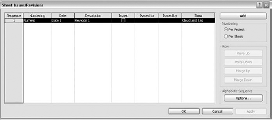
Figure 12.34. Creating new revisions, organizing their sequence, and controlling their behavior are possible with the Sheet Issues/Revisions dialog box.
When opening the Sheet Issues/Revisions dialog box for the first time, you will see that Revit Structure has already created a revision for you and it can't be removed. You can use this as a starting point. Each revision has a fixed number of parameters available.
To help you better understand the various settings in the dialog box shown in Figure 12.34, we will briefly explain what each section does. To further expand your knowledge from what is shown here, browse through the help guides that are part of Revit Structure by searching for "Revisions."
- Sequence
Revit Structure gives each revision a sequence number. This parameter can be added to a Revision Schedule to help sort the order of revisions placed on a sheet. This is Revit's own unique revision ID.
- Numbering
The Numbering parameter is used to select the display of numeric, alphabetic, or no numbering for each revision. This value is typically displayed in a revision delta. If a numeric number method is selected, it will display numbers in sequential order, such as 1, 2, 3, 4, 5, etc., as each revision is created.
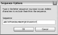
If an alphabetic numbering method is selected, it will pull its information from the alphabetic sequence list shown in Figure 12.35. This list can be found by clicking the Options button in the lower right-hand corner of the Sheet Issues/Revisions dialog box. Each revision will display the next character in line, such as A, B, C, D, E, etc., as each revision is created. This is intended to give you the ability to decide whether potentially ambiguous letters like I or O are allowed as revision values.
Note that the alphabetic sequence cannot contain spaces, numbers, or repeated characters. If you attempt to use this format, Revit Structure will display a warning to remind you of this.
- Date
The Date parameter is used to display the date of issue for the revision in a Revision Schedule on a title block.
- Description
The Description parameter is used to explain why the revision exists, and you can add it to a Revision Schedule on a title block.
- Issued
The Issued parameter is used to mark a revision as having been issued. This locks the revision clouds that are placed throughout the model so that they cannot be moved, deleted, or edited. If you try to move one, Revit will generate a warning dialog box that includes an option to "unissue the revision." This helps ensure that revision clouds don't get moved after they are issued. Keep in mind that the revision clouds do not automatically move when other modeled or annotation elements move, so it is possible to have the revision cloud not encompass its intended revision.
Issued revisions cannot be modified within the dialog box either except to provide Issued To or By information. You cannot place a revision cloud and assign it to an issued revision. If you need to do this, you will first need to change the revision so that it is not issued. When you place new revision clouds, they will automatically get assigned to the last unissued revision in the revision list.
- Issued To
The Issued To parameter can be used to display information about whom the revision is being issued to. If you don't usually show this information on documents, this field can be used as an alternative field to display information other than an Issued To value.
- Issued By
The Issued By parameter can be used to display information about who is issuing the revision. This field can also be used differently like Issued To if necessary.
- Show
The Show parameter allows you to display the tag, the cloud and tag, or neither before or after it is issued. Many firms prefer to show clouds only for the latest revisions. They leave only the tag visible for earlier revisions. Thus, these choices usually offer enough flexibility so you can display the information that you need at the time you need to display it.
- Numbering area
The Numbering area of the Sheet Issues/Revisions dialog box is where you can set the revision behavior to Per Sheet or Per Project. This affects the entire project revision scheme. This option can be set to however your company prefers to track revisions on sheets or to match how the architect is tracking them. This setting can be a big deal to the people in your firm who see the construction of the project through to completion. You can change the setting here, but it will alter how all of the revisions are identified, and you will have to verify that everything is correct.
When using the Per Project method, each revision gets assigned a numeric or alphabetic value depending on what revision it is. No matter which number of revision may be on a particular sheet, it will always display the same value. For example, if revision 3 was the fifth revision in the Sheet Issues/Revisions dialog box, it would display the value 5. Wherever that revision was detected on a sheet or set to display on a sheet through the sheet properties, it would display the value 5.
When using the Per Sheet method, each revision gets assigned a numeric or alphabetic value depending on what revision it is on that particular sheet. Each revision is given a value depending on how many revisions are on a sheet. For example, if revision 3 was the fifth revision in the Sheet Issues/Revisions dialog box and was the second revision on a sheet, it would display the value 2.
- Row area
The Row area of the Sheet Issues/Revisions dialog box is where you can rearrange the order of revisions or merge them with other ones. How often does it happen that you are working on revision 3 and you get the call, "Can we quickly issue this one detail as revision 3 and put everything else you have been working on for the past three days on revision 4?" Well, this is how you would handle it. You can add a new revision, move it up ahead of revision 3, swap the names, and can continue on your way.
- Alphabetic Sequence area
The Alphabetic Sequence options are used when the Numbering method is set to Alphabetic. This dialog box sets the sequence to be used for alphabetic characters as revisions are placed on sheets.
You will find that learning how the tools in Revit Structure work for creating sheet content and tracking revisions will help you learn some workaround solutions that can be done to achieve the behavior of several standards that may be required. You will want to take full advantage of everything pertaining to your deliverables and what sheets can do for you so you can spend your time designing and documenting the structure rather than coordinating the placement of your information, as it may change as a project evolves.
- Create a title block to display project information
The basics of creating a title block include using line work, annotations, filled regions, labels, and images. Combining these basic elements to create parametric behavior will take you way beyond 2D drafting.
- Master It
What are three ways you can make your title blocks parametric to autoadapt to changes that are made within your sheets?
- Create a Revision Schedule to your company standards
Revision Schedules added to title blocks allow you to keep track of revisions on sheets. You can design these Revision Schedules to accommodate just about any company standard and title block configuration.
- Master It
How do you rotate a Revision Schedule 90 degrees? How or where do you set a Revision Schedule to display its information from the bottom up?
- Explore the behavior of the various view types when they are placed on a sheet
When views are placed on sheets, new parameters become available that display information that is specific to how and where the views are placed. Each view can have a different behavior; knowing this behavior allows you to take advantage of it.
- Master It
What are four parameters that become available in plan, elevation, detail, drafting, and 3D views when they are placed on a sheet? What types of views can be placed on a sheet more than once without being duplicated?
- Produce a drawing list/sheet index to keep track of your issued sheets
Revit Structure lets you easily create a drawing list/sheet index to keep track of sheets.
- Master It
How can you get additional information on your drawing list to manually account for issue names and descriptions as well as to show which sheets are being or have been issued?
- Control the behavior of revisions in your project
You can control the tracking of revisions made to the model to reflect several standards that may be required as well as react to unknown project schedule changes.
- Master It
How do you set a revision tag to display an alphabetic sequence "numbering" standard? How do you rearrange a revision to be put on hold so that it can be used after others instead?