
There are two ways you may have arrived at this chapter. One is you read through the book in its entirety and are now ready to start creating some families. The other way is you went out, bought the book, and flipped directly to this chapter with the sole purpose of learning this part of Revit Structure. Whatever path brought you to this point, you now know that Revit Structure is very much dependent on family objects to drive the model. For all of the advantages of Building Information Modeling (BIM) and the smooth workflow Revit Structure can provide, you will find that you are going virtually nowhere unless you have the content you need. Yes, Revit Structure does provide a rich library of content out of the box that will get you through most areas of a project, but what about the specialty content you need? It would be literally impossible for Revit Structure (or any CAD application for that matter) to provide a predefined custom family for every situation. Add to that the need to re-create that special family within your company's set standards, and the task becomes even more impossible.
Revit Structure acknowledges this and takes a different approach. Instead of attempting to provide a specific family for every situation, Revit Structure provides general templates (.rvt files) that allow you to choose the basic type of family object you want to create. Each family in Revit Structure is built with the flexibility to adapt to as many situations as possible. For example, say you need to add a lintel to your project. In AutoCAD, you might have a block that is inserted into your detail drawing. You can then edit the block scaling or explode and modify that block to suit your specific dimension requirements. Then you need another block or additional line work in plan to document the lintel. In Revit Structure, you make one lintel family starting with a Revit Structure family template, with parameters that allow you to change the size, shape, and anything else you need adjustable in the family. You can also create the family to display the line work in plan. Taking it a step further, you can even use the family to produce schedules and material takeoffs.
At its heart, Revit Structure is driven by families, and it depends on families to enable its parametric concept. Some families will be quite simple to create once you understand their basic structure and function. Families don't need to be complex to be well constructed. Others are going to be more difficult and will require more thoughtful consideration and good old-fashioned patience. Either way, learning the ins and outs of creating Revit Structure families is not something that will be accomplished overnight. Rome was not built in a day, but little parts of it sure were.
In this chapter you will learn to:
In Revit Structure, a family is named family for a couple of reasons. One is the hierarchical concept that drives its organization and functionality. The second is the ability to deliver multiple types (or members) of the family to a project, all of which are contained in one package. It is similar to when a minivan pulls up to the picnic area of a local state park and eight people, all parents or siblings, start piling out of the vehicle. The same concept holds true for a Revit Structure family. The van represents the family and the eight members of the family on the picnic represent the different family types being delivered.
In Revit Structure, there are three kinds of families:
- System family
Although you may not be aware, you have been using this family type throughout this book. A system family is defined within the project and is not an external file that needs to be loaded. It has a predefined purpose and capabilities that you cannot change, only use. You can edit a system family by modifying the parameters provided in the Element and Type Properties dialog boxes. You can also define the extents of many system families in Sketch mode. Some of the model elements contained within the project that are system families include
Walls
Wall footings (strip footings)
Floors (slabs)
Roofs
Stairs/ramps
Toposurfaces
Openings
Dimensions
There are also several system families that incorporate a component family, an external file, for a portion of their definition. These particular system families have additional flexibility to customize their look or the profile used to create them. Some of these include
Grids
Levels
Spot elevations
Spot coordinates
Railings
- In-place family
This type of family resides completely within the model as well, but when you issue the Model In-Place tool and select the category of the in-place family, the Ribbon switches to the Family Editor. You can then create the family components in their required position without the need to insert and then position them correctly. Also, in many cases you will need to use the existing model elements to lay out the geometry of the in-place family. This functionality is very important in Revit Structure since there will always be areas of a model that need a custom touch.
- Component family
This type of family is created and managed externally and then loaded into the Revit Structure model as needed. For instance, if you wanted to add a castellated beam to the model, you would have to load it from an external family file (file extension
.rfa). By default, Revit Structure does not have this type of beam family loaded into the model. After you execute the Beam tool, you can load a new beam family by selecting Load Family in the Detail panel of the Ribbon. Then you can browse for the family you need, and it will be loaded into the project for future use. It is obviously preferable to have a library of families available for use, but in the interest of maintaining an organized model with a manageable file size, families shouldn't be loaded into the model until you actually need them.
Constructing a family in Revit Structure is a unique process, and you will probably find it unlike any of your experiences with other CAD applications. At first you may see the family-creation process as cumbersome and somewhat unwieldy. It may seem like more than it is worth to create a family for a model element that may be needed for only limited use, but then you realize how much potential your creation has. After some practice using the tools, you will see the overwhelming advantage of constructing these components. To get a feel for family creation, we will use a stepped footing example. It will be similar to the stepped footing you have already used in Chapter 8.
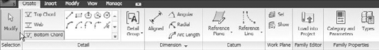
To begin creating a family file (.rfa), you should first decide on a template that is close to what you are trying to create. Revit Structure provides templates for most situations. For example, if you started a new truss family, you would begin with the Structural Trusses.rft file found in the Imperial Templates directory. Once this template is opened, the Ribbon reflects this with tools specific to the creation of trusses, as illustrated in Figure 18.1. Specific materials are preloaded into these templates as well, along with logical setting defaults related to the family category.
The process for starting a new Revit Structure family is to choose New
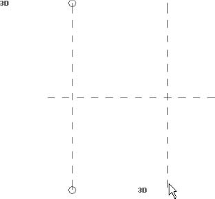
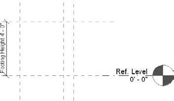
Once you are in the desired template, you are basically on your own. As you can see, you are given very little graphical information to begin with. If you look at the Project Browser, you will see Revit Structure has provided several views of the family for you. These include a floor plan, four elevations, and a 3D view. The Project Browser allows you to navigate around the family just as you would navigate a Revit Structure project. You will most certainly use all of these views at some point, but for now let us concentrate on the Floor Plan: Ref. Level view.

Figure 18.2. The New Family dialog box, allowing you to choose from one of the predefined Revit Structure family templates
With the floor plan open, notice the two green dashed lines. These are reference planes. Depending on the template used, Revit Structure often will start you with at least two of these in plan view and usually a datum (a level) reference in elevation view, thus the floor plan name Ref. Level. When you are constructing a family, these reference planes are critical to your success. They are used to constrain the family, which allows the users input to determine the resulting geometry. To make a long story short, reference planes help define the family and control placement in the host model.
In Figure 18.3, you will see two reference planes. These two reference planes are important, and you should always build from them when creating families. You should not modify or move these planes, as they define the origin and insertion point of the family. Follow these steps:
Select one of the reference planes. You will see the name of the reference plane, as shown in Figure 18.3. This particular name indicates it serves a specific purpose.
With the reference plane selected, choose Element Properties

You will see this plane's specific reference is the center of the family in the front/back direction, which is reflected in the value of the Is Reference parameter. It has been named the same as its given reference for continuity (Name parameter).
You will also see a check box next to the Defines Origin parameter. Highlight and view the Instance properties of the vertical reference plane, and you will find it serves an identical function in the left/right direction.
This further indicates that these two reference planes have special value, and each should be used as a datum when constructing families.
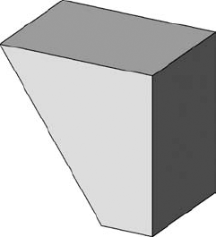
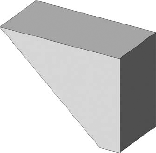
The family we are about to create is the footing step illustrated in Figure 18.4. The objective is to make the family dynamic enough to work with any stepped situation. This means the dimensions and geometry need to be flexible enough to allow the family to be placed manually and then adjusted to fit the needed condition.
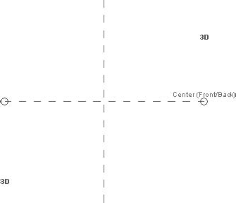
Figure 18.3. These reference planes define the origin of the family and should be used as a starting point for family construction.
To create the required dimensional constraints, you will need to add additional reference planes offset from the existing reference planes shown in Figure 18.3.
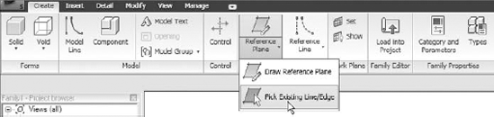
To do so, focus your attention on the Ribbon. On the Create tab, you will see a Reference Plane button. When using this tool you have the choice of drawing reference planes from scratch or picking existing lines to create them.
Choose Reference Plane
Once you have launched the Reference Plane tool with the Pick Existing Line/Edge option, you will notice the Options bar now contains an Offset edit box.
Assign an offset of 4′-0″ You can now create a reference plane 4′-0″ from the existing vertical reference plane in the view window.
When you hover the cursor over the existing vertical reference plane, you will see a blue alignment line indicating the new reference plane to be created.
Move your cursor to either side of the vertical reference plane to assign your offset side. Click to place the new vertical reference plane. Your view should now look like Figure 18.6.
The strategy for this example has the insertion point at the right midpoint of the footing step when it is inserted into the model. The vertical origin plane will take care of this in the vertical plane. In the horizontal plane, however, you need to add two more reference planes to center the footing step on the horizontal origin plane. You need one above and one below.
To do this, start the Reference Plane tool with the Pick option as before.
Create an offset horizontal reference plane 1′-0″ above and 1′-0″ below the origin plane, leaving you with three horizontal reference planes, as shown in Figure 18.7.
At the bottom of the footing step it will be nice to have an extension, which will provide more bearing surface against the bulkhead of the wall step. Normally this is a 6″ extension of the wall footing. We can build this feature right into the footing step family. Using the Reference Plane tool, offset a reference plane 6″ to the left of the vertical origin plane. This will establish a plane to model any additional cover you may wish to add to the step. Later on, you will create an extrusion that will be locked to these planes. When the reference planes move, the extrusion will follow.
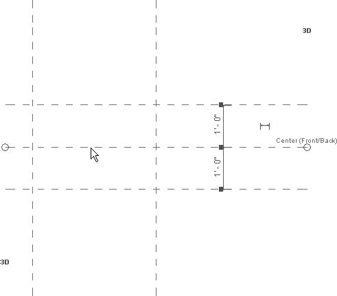
Figure 18.7. Adding two additional reference planes to center the footing step on the horizontal origin plane
In plan view, the planes needed to create the footing step geometry have been accounted for. Now it is time to look at the third dimension.
In the Project Browser notice there are four elevation views predefined. Choose the front elevation. You can now see a Reference Level datum and three reference planes, including the two we added, in the plan view. You now need to add a reference plane that reflects the height of the footing step. To do this, follow the same procedure as you did in the plan view. You may notice there is a reference plane as well as the Reference Level datum at 0′-0″. It is good practice to align the reference plane to the datum and lock these two elements together. The datum line is the strongest elevation reference in the family, and the reference plane is tackling the origin reference duties, so generally you will want them to be aligned. This will prevent the family from behaving erratically when placed in the model.
Using the Reference Plane tool, create a reference plane that is offset 4′-0″ above 0′-0″, as shown in Figure 18.8.
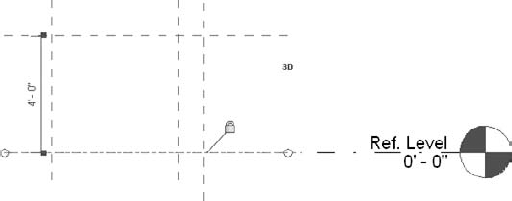
Figure 18.8. Establishing a reference plane in an elevation view is done exactly as it is in plan view. Remember to lock the origin reference plane to the datum elevation.
Since this is a relatively simple family, these are all the reference planes we will need. It is helpful to look at this procedure the same way you would look at the procedure for creating a steel-framed structure for a building. These reference planes are the structure of the family and serve as its backbone. Any additional elements we add are going to be locked to these planes and will be controlled by them. Once this family is loaded into the model, the reference planes we just added will not be visible, but the model elements such as the concrete step will be influenced and controlled by the planes.
Now that the reference planes are in place, it is time to add some parameters to your family. These parameters will serve as labels to control the dimensions of the reference planes. When you do this, the end user can go to the Element properties of the footing step and input new dimension values, creating different configurations of the same footing step family.
If you are thinking this is the fun part, then you are correct! Adding flexibility to families is at the heart of the functionality Revit Structure provides. Once you witness the potential of this concept, you will never want to go back to a traditional CAD platform again. Fundamentally this procedure is simple. Of course, when you begin creating more complicated families, it naturally gets more complex, but the base concept is grounded in simplicity. You need to dimension these reference planes so you can then add labels to those dimensions. Those labels reference parameters the user sees in the Element Properties dialog box. For instance, you added a reference plane 4′-0″ above 0′-0″ in the front elevation. The next step is to add a 4′-0″ dimension and label it Height. Now, the user can change the Height parameter to 5′-0″, and voilà! The footing step becomes 5′-0″ high. To start adding dimensions, do the following:
Return to the Ref. Level plan view. Again, one really nice thing about the Ribbon is that it makes it easy to get to the tools you need.
On the Detail tab of the Ribbon, in the Dimension panel, you will see an Aligned button. Click it, and place a 4′-0″ dimension, as shown in Figure 18.9. Be sure to dimension from the Center (Left/Right) reference plane.
You should base your family dimensioning strategy from the origin reference planes whenever your family strategy allows. This will lead to much more stable families when it comes time to place the new component into your model. You should also note that a label can't be applied to a dimension string spanning more than two elements, so most dimensions in families will be placed individually. An often-used exception is when a string is used to define an equal-spacing constraint. You will be placing one such string a bit later.
Dimension the reference planes as shown in Figure 18.9. After the reference plane is dimensioned, you can then select the dimension.
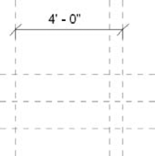
Figure 18.9. Dimensioning the reference planes is the link between the physical geometry and the element parameters.
As is true for any Revit Structure element, once the item is selected, you will be presented with choices on the Options bar specific to the selection. In this case, we are interested in the Label option.
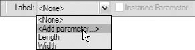
Select the <Add Parameter> item from the Label drop-down list, as shown in Figure 18.10.
Notice that there are two parameters already defined in the template and listed here too, Length and Width.
The Parameter Properties dialog box, as illustrated in Figure 18.11, is very powerful despite its simplistic appearance. Some of the choices you make here are unchangeable, so be deliberate when you are creating these parameters. In the Parameter Properties dialog box, the first set of choices deals with the type of parameter you wish to use: Family Parameter or Shared Parameter. Each has a specific purpose.
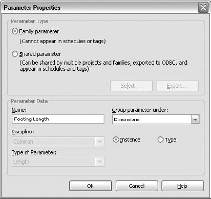
Figure 18.11. The choices made in the Parameter Properties dialog box influence the behavior of the family.
Shared parameters should be used when the parameter's value needs to be used by other families or projects. When shared parameters are created, information is stored in an external .txt file. This text file can be used while editing families and projects, and the parameters contained within can be added wherever they are needed. An example of a situation where you would want to use a shared parameter is if you were planning to nest the family within another that would then need access to its parameters, such as if you were creating a foundation family that included a nested pilaster. Shared parameters would allow you to change the pilaster's parameters within the foundation family.
If you choose to create a family parameter (which is the default), it will be used by this family only and will not be accessible to other families. Given the specific nature of this type of parameter, it would be impractical to allow it to show up in schedules and tags because it is specific to only one family. You would wind up with a separate schedule or tag for each family. This is obviously not desirable, so Revit Structure does not allow it. A family parameter should be used when there is no need for the parameter's value to be used in another family.
For now, choose Family Parameter, as shown in Figure 18.11.
The first item in the Parameter Data panel of the Parameter Properties dialog box is Name. Remember that you accessed this dialog box after selecting the 4′-0″ dimension. For clarity, the parameter name should describe its purpose. This may be related to the item you are labeling or the dimension you are controlling. Do the following:
Name this parameter Footing Length.
Notice the name Footing Length contains capital letters. This comes into play if the parameter is later used in a formula. Formulas are case sensitive and must include the exact parameter name. A popular convention is title case; that is, all the important words in the name are capitalized. However you choose to name your parameters, you should be consistent.
Notice that the Discipline and Type of Parameter data fields have been automatically assigned and are unavailable for modification. They are not editable because Revit Structure knows you chose a dimension to apply this parameter to, so the Discipline value is automatically going to be Common, and the Type of Parameter value is going to be Length. Again, both of these values can make a huge difference if the parameters are used in a formula. This is the advantage of creating a parameter by selecting a dimension first. It isn't possible to assign the wrong type of parameter.
The Group Parameter Under drop-down list allows you to categorize the parameter under a specific heading (Group) in the Instance Properties dialog box. This type of length parameter is almost always grouped under Dimensions. Some parameters may not lend themselves to one category over another, and that is why Revit Structure has provided a group called Other. Regardless, in these cases you will need to use good judgment.
Assign the Dimensions Group parameter.
The next option is Instance or Type. This is arguably the most important choice of all. If you decide this will be an Instance parameter, you are saying, "I want this parameter to be independently editable, unique, for every instance of the family object." For example, if you select the footing step after you insert it into the model and open the Instance Properties dialog box, you will see a list of Instance parameters of the family. If you change any of these parameters without clicking the Edit Type button, only the footing step you selected will be modified with the changes you make. The rest of the footing steps in your project will remain unmodified. If you choose to create a Type parameter, you will need to first select the footing step in the model, then click the Element Properties drop-down list, and click the Type Properties tool. There you will find a list of Type parameters. If you edit these parameters, you will change all of the footing steps of the same family and type in the entire project. Then if you needed a different set of Type parameter values, you would need to duplicate the type to create a new one. For the footing step, you will be making all but one of the parameters Instance parameters.
For this parameter choose Instance.
Now click OK, and the dimension will contain the new label, as shown in Figure 18.12.
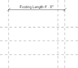
Figure 18.12. The Footing Length label has been added to the new dimension, which is now controlled by the Footing Length Instance parameter.
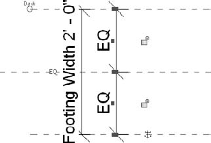
Now it is time to dimension and label the two 1′-0″ offset reference planes you added earlier. The distance between these two reference planes represent the overall width. You will, however, need to tell Revit Structure that although the width will vary, it should always be equally spaced about the origin reference plane. To accomplish this, follow these steps:
Use the Aligned dimension tool and place a two-dimension string that includes all three horizontal reference planes.
Once the dimension has been placed and is still selected, click the blue EQ icon, but don't click the padlocks. This will create a relationship between the reference planes relative to the center reference.
Now add one more dimension to the overall 2′-0″ width, select it, and create a parameter called Footing Width.
Make sure the parameter is grouped under Dimensions, as shown in Figure 18.13. This parameter should be created as a Type parameter.
You also need to dimension the 6″ offset reference plane and give it a parameter called Footing Cover, but let's do something a little different this time.
Dimension the 6″ offset reference plane, but instead of selecting <Add Parameter> from the Label drop-down list, click the Types button located on the far right of the Ribbon in the Family Properties panel.
This brings up the Family Types dialog box, as shown in Figure 18.13. While parameters that are used as labels for dimensions can be created through the Options bar drop-down, other kinds of parameters must be created here. You see the parameters you have already created here under Dimensions as well as the values that were automatically applied to them from the dimensions you labeled.
In this dialog box on the right near the bottom you see the Parameters panel. Click the Add button and you will see a familiar dialog box.
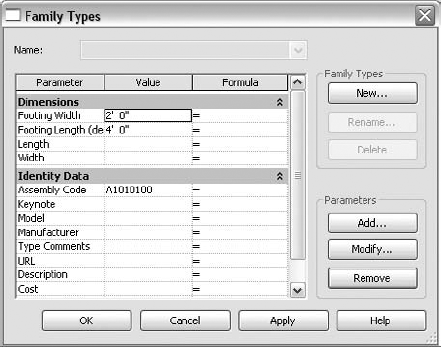
Figure 18.13. To access the Family Types dialog box, click the Types button on the far right of the Ribbon in the Family Properties panel.
This is the same process as before, just a different way to go about it. Notice that the Discipline and Type of Parameter options are available here. That is because Revit Structure does not yet know this parameter is meant for a dimension label.
Create the Footing Cover parameter as you did the others before, taking care to select Common for Discipline and Length for the Type of Parameter option.
Set it to be an Instance parameter grouped under the Dimensions category. The parameter has been created but has not yet been applied to the dimension.
Click OK twice, and we will do something about that.
Back in the plan view, highlight the 6″ dimension and look at the Label drop-down list. You will find the newly created Footing Cover parameter there.
Select it, and the label is applied and the parameter takes on the default value of the dimension. You can verify this by returning to the Family Types dialog box if you want.
These two methods achieved the same result but went about it a bit differently. Adding a label to a dimension is certainly more streamlined using the Label drop-down, but using the Family Types dialog box is required knowledge for anyone who creates families because there other types of parameters than those for dimensions. All of the necessary plan dimensions have now been added, as shown in Figure 18.14.

Figure 18.14. The reference planes now have the added dimensions and labels. Notice that the first two center reference planes are being used as the origin.
Are you starting to see the process? You build the geometry with reference planes, and then you dimension and apply parameters to them to make them parametric. To continue, follow these steps:
Display the front elevation where you added the reference plane 4′-0″ offset of the datum elevation.
Add a dimension from the origin reference plane located at 0′-0″ to the top reference plane you added previously. The procedure is the same as in plan view.
Select the dimension and use the Label drop-down menu to create a new parameter named Footing Height. Make it a Type parameter for now—we'll show you how you can change it later if needed
Apply it to the 4′-0″ dimension, as illustrated in Figure 18.15.
Now is a good time to test the family before you get too far along. If you were to wait until the family was finished to test it, the cause of any problems you may encounter would be much more difficult to determine. Once you have established the majority of the reference planes and have applied parameters to them, you can start to flex the family to shake out any unexpected results before adding the physical geometry:
To see how your family reacts to changes, click the Types button on the far right of the Ribbon to open the Family Types dialog box once again.
Like most windows, this dialog box can be resized by dragging any edge or corner. The width of all columns will grow as you increase the width of the dialog box. In addition, if you hover the cursor over the line dividing the headers, you can adjust their widths individually.
Do this between the Parameter and Value headers, and drag slightly to the right so you can read the entire Parameter column.
Notice that the parameters that have (default) next to their name. This indicates they are Instance parameters, and the value listed here is the value the parameter will have when it is initially inserted into a project.
These parameters can be edited. If, for example, you forgot to make a parameter an Instance parameter, you can correct it by selecting the parameter in question and clicking the Modify button in the Parameters field in the lower right of the dialog box, as shown in Figure 18.16. This returns you to the Parameter Properties dialog box, where you can make needed changes.
For this footing step family, click Modify and make sure each of the parameters you added except Footing Width is an Instance parameter.
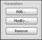
Figure 18.16. First select the parameter you wish to modify, and then choose Modify. Parameters can also be added or removed here.
To test the family, modify the value that was established to the right of the parameter name.
While still in the Front Elevation, drag the Family Types dialog box to the side so you can see the Footing Height dimension; then change the Footing Height value to 3′-0″ and click Apply.
Notice that the reference plane representing the top of the footing step moved down to reflect the new value. The origin reference plane acts as an anchor in this situation, and you can now see why you should dimension from origin planes whenever possible.
Return the value to 4′-0″ and click OK. Now go to the Ref. Level plan view so you can test your other parameters.
After relaunching the Family Types dialog box, change the Footing Length value to 5′-0″, click Apply, and then change it back to 4′-0″.
Change the Footing Width value to 3′-0″ and click Apply.
Notice that your reference planes move away from the origin reference planes even when an equal dimension string is involved. This procedure is called "flexing the family," and you should do this to test every parameter you create.
Return the Footing Width value to 2′-0″.
Now, suppose you wanted the Footing Cover value to be a function of the Footing Length value. You can achieve this by using a formula in the Family Types dialog box. To the right of the Value column, you will see a Formula column. Here Revit Structure will accept a formula and evaluate it, and the resulting value will be applied to the parameter. Again you can adjust the size of the dialog box or drag the column widths if you need to.
Open the Family Types dialog box, find the Footing Cover parameter, and under the Formula column type Footing Length / 3, as illustrated in Figure 18.17 (the formula is case sensitive).
When the Footing Length value changes, the Footing Cover value will equal the Footing Length value divided by 3. Formulas can contain mathematical functions,
if/thenstatements, and much more. Consult the Revit Structure help file for the exact syntax and all supported expressions.
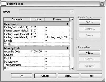
Figure 18.17. You can add a formula to the Formula column in the Family Types dialog box. Remember that the expressions are case sensitive.
Now that the skeleton of the family is firmly in place, it is time to add the physical solid that you will see in the project. The extrusion that you will add will be locked to the reference planes that you have created and will be controlled by the values for each parameter.
You have finally made it to the fun 3D part. Once the family is flexing correctly, the hard part is over, and you can usually wrap it up by adding a simple extrusion or two. There are, however, still a couple of tricky details to deal with. The first is establishing the plane you want the extrusion sketch to be drawn in. You will create this extrusion in the front elevation view, but if you start the Extrusion tool (Forms panel
In the Ref. Level plan view, the horizontal reference plane you added below the origin plane is at the front of the family, and the one you added above is at the back.
Select the front reference plane and choose Element Properties
In the Instance Properties dialog box you will see a Name parameter. Name the reference plane Front and click OK.
Then repeat the procedure for the back plane and name it Back.
Notice that now when you select the back plane, you can see its name in the drawing area, as shown in Figure 18.18.
Switch to the Front Elevation view.
Choose Solid
Now that it has a name, our preferred plane appears in the drop-down list. Select Reference Plane : Back, as shown in Figure 18.19. Click OK to close.
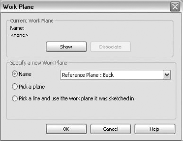
Figure 18.19. It is important to have a clear naming strategy for reference planes. New reference planes become available as a work plane selection only after they have been named.
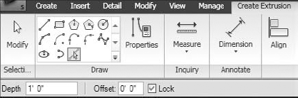
You will now find yourself in Sketch mode with a Create Extrusion tab to work from. The Options bar will also be of use to you. In the Draw panel of the Ribbon, you will find several options for sketching. One of the most useful is the Pick Lines option, especially when it is used in conjunction with the Lock option on the Options bar, as illustrated in Figure 18.20. While the lines can be sketched, aligned, and locked manually, this combination is usually more convenient.
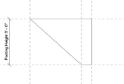
Figure 18.21 shows the footing step shape. It is easiest to select the reference planes to create the sketch where possible.
Sketch the three lines that fall on reference planes using the Pick Lines and Lock options.
Select the Draw Lines option (top leftmost option in the Draw panel) and sketch in the diagonal line.
Be sure to snap to the reference plane intersections when drawing the diagonal; use the keyboard shortcut for intersection (default is SI) to bring up only the intersection snap if needed.
Once you have the perimeter of the extrusion sketched in, use the Trim tool in the Edit panel of the Ribbon to clean up the corners.
Notice when you select a sketch line that you see the lock symbols for the three sides that are constrained to the reference planes. Next we will illustrate how you might accomplish this without the Pick Lines and Lock options:
Click the lock symbol for the right vertical sketch line to unlock it. Now select and drag the line a few inches to the right.
Choose the Align tool from the Edit panel of the Ribbon, and align the sketch line to the origin plane once again; pick the reference plane first.
Once this line is aligned, a lock symbol will appear but will remain unlocked. This is your opportunity to lock the sketch line to the reference plane, and you should do so now.
You can also align the end point of a sketch line if you need to. This align-and-lock combination is used often to constrain geometry when creating families.
Now that the perimeter is sketched and locked to the reference planes, you need to specify a material and an extrusion depth.
In the Element panel of the Ribbon, you will see the Extrusion Properties button. Click it and navigate down to the Material parameter.
The default material value is <By Category>. Since you know this footing step will be cast-in-place concrete, you can specify this as its material.
If you click within the Value field, a small browse button ([...]) will appear on the right side of the field. Once you click this button, the Materials dialog box will open.
Here you can select Concrete - Cast-in-Place Concrete and click OK.
This returns you to the Instance Properties dialog box, where you will see this value added, as shown in Figure 18.22. If you do not assign a material, one will be automatically assigned using the default material for the category you specified for your family.

Figure 18.22. You can add a material by clicking the browse button in the Value field of the Material parameter.
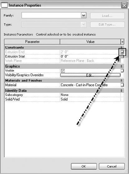
In the Instance Properties dialog box you will see three parameters, but only two that you can change here, Extrusion Start and Extrusion End, that deal with the extrusion's constraints, as shown in Figure 18.23. Since you know Extrusion Start refers to the plane the perimeter was sketched on (the back reference plane in this example, which you can see in Work Plane parameter), this value can remain 0. The Extrusion End parameter, however, needs to be the same as the Footing Width parameter. You could simply type the width in the Value field and the extrusion would adjust accordingly, but if you were to flex the model, the extrusion depth would remain at that fixed value you specified.
To apply the Footing Width value to this parameter, look to the right of the Value column. There is an = column. Within the = column you will see a small gray button, as pointed out in Figure 18.23. Click this button (Associate Family Parameter), and you will get a list of length parameters to choose from.
Select Footing Width, and now the Extrusion End parameter will match the value of the Footing Width parameter.
Click OK; now the small gray button shows an equal sign, and the field is grayed out.
As with many tasks in family creation and Revit Structural in general, there is usually more than one way to achieve an objective. For example, in this situation, instead of applying the Footing Width parameter to the extrusion width, you could choose to finish the extrusion and then align and lock it to the front and back reference planes in the Left or Right Elevation view.
Once the Extrusion End and the Material parameters have their values assigned, you are finished in this dialog box and can click OK.
On the far right of the Ribbon in the Extrusion panel, click Finish Extrusion.
Go to a 3D view to be sure the shape looks the way you expected it to.
At this point it is strongly recommended that you flex every parameter once again while viewing the family in 3D, as shown in Figure 18.24.
You name the family by saving the file with a specific name. If you have not already done so, click the Save button, browse to an appropriate location, and name the footing step family Footing Step. You can download the finished Footing Step.rfa file from this book's website at www.sybex.com/go/masteringrevitstructure2010.
You have one more thing to do before inserting this family into a project. You should always assign the family a category. In this case, it would be nice to be able to insert this family as an isolated foundation as opposed to a generic model. The ability to do this not only makes the process more organized but also allows this family to automatically join with adjacent foundations in most situations. To check or modify the family's assigned category, find the Family Properties panel on the right end of the Ribbon and click the Category and Parameters button. Notice in Figure 18.25 that this specific family is already categorized as Structural Foundations. This is because you used the Structural Foundation template when you created the family. If you had used a generic model, you would have had to modify the family category. Click OK once you have verified the family's category.
To add the family to a model, you need to either start a new project or open an existing one. The project file should be open but in the background, and the family file should be open and active.
Within the family file (
Footing Step.rfa) click the Load Into Project button in the Family Editor panel of the Ribbon. The project will become active.The Footing Step family now appears in the Type Selector as the current type. Click the Change Element Type drop-down, as shown in Figure 18.26.
You will see Footing Step as one of the choices in the Type Selector on the Options bar. Notice that this family is one of two isolated foundation families available (if you open a default template). The Footing Step family looks a little different from the Footing-Rectangular family. They both display a small preview of the family, but the Footing-Rectangular family has multiple types available, while your Footing Step family offers only the default type.
To create types of different sizes for your new family, switch back to the family file and click the Types button in the Family Properties panel. You will recognize the Family Types dialog box from when you added the parameters and flexed the family. In the upper right of the dialog box you will see a Family Types panel, as pointed out in Figure 18.27. Also notice that the Name drop-down at the top of your dialog box is currently not available. This is because only the default type exists.
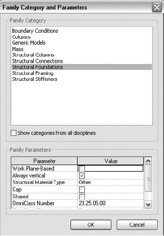
Figure 18.25. To be sure this family is assigned the Structural Foundation category, click the Category and Parameters button on the Ribbon.
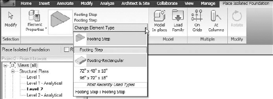
Figure 18.26. In a project, the Footing Step family is identified by its filename in the Type Selector.
Imagine your project had two wall footing conditions you needed this family for. One was a wall footing step where the footing was always 3′-0″ wide, and another was always 6′-0″ wide. You can make a type for each of these conditions:
Under Family Types, click the New button, and you are immediately prompted for a name.
Name the new type 3′-0″ Wide and click OK. This will be a descriptive name for the width you are about to apply to the type. Notice that the Name drop-down now displays the name of your new type. This is an indication you are editing that particular type.
Change Footing Width to 3′-0″.
Click New again, and add a type named 6′-0″ Wide. You guessed it, change the Footing Width value to 6′-0″ for this type. Notice that now you can switch between the types in your family, as illustrated in Figure 18.27.
Simply select one from the Name drop-down and click Apply. The family updates in the drawing area, and its parameters are editable.

Once you have finished, you can load the updated family back into the project, and choose Overwrite to overwrite the existing version. Now when you execute the Isolated Footing tool within the project, you now have two variations of the same family: Footing Step: 3′-0″ Wide and Footing Step: 6′-0″ Wide. Because you created Footing Width as a type parameter, it can be different only in different types of the family. The Instance parameters are all freely editable in every instance regardless of type.
Real World Scenario: When to Stop!
At my company we jumped right into using and customizing Revit Structure with little reservation. We took every AutoCAD block and rebuilt it as a Revit family file. In AutoCAD we had over 60 pile caps of various size and configurations. So we created a single family file with all forms in it. Seemed like a great idea at the time. Whenever we wanted to add something new, that proved to be a real hassle since we had to keep all the various types in the family in mind. The other major hassle was whenever a new type needed to be loaded, the single act of loading a single new type could take minutes, not seconds.
It is sometimes difficult to know where to draw the line as far as trying to capture every size configuration in individual family types. Typically you can create a family and provide the end user with two or three size configurations to use as templates. Once the user adds the family to a project, the provided types can be duplicated by selecting the family and choosing Element Properties
Some families you create are going to very simple. Some families you will attempt to create may require "Ninja" skills. Either way, it is quite obvious that the more you learn about creating stable, intelligent families, the more benefit you will reap by choosing to use Revit Structure. In many cases, success in Revit Structure and BIM in general depends on how proficient you are at creating families.
Exercise: Creating a Bridging Family
The following activity involves creating an uplift/joist bridging family. It includes family-creation concepts along with practical uses and applications. This family will be placed in a roof-framing plan by drawing a single line. The graphic representation will be a symbolic line in plan. In section view, there will be an angle seated on the bottom of the joist for detailing purposes. If at some point during the exercise you are prompted to save or you need to stop working on it for awhile, just save the file as Joist Bridging.rfa. The only steps you must complete first in order to save fully are those that require a sketch mode, like creating a solid sweep. Otherwise, you can save and return later.
To get started, open Revit Structure and in the Application menu (R in the upper-left corner) choose New
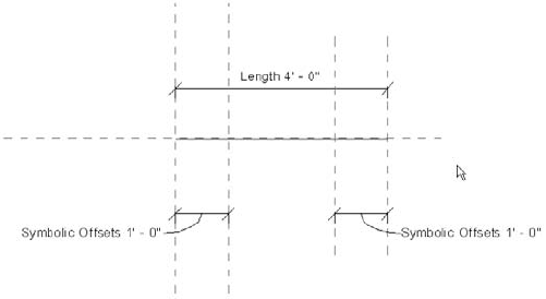
While in the plan view, on the Create tab in the Datum panel, select Reference Plane
Dimension the two new reference planes to the two existing references planes.
Select both new dimensions and add a label to each. Call the new label parameter Symbolic Offsets, group it under Graphics, and make it an Instance parameter.
In the Family Properties panel of the Ribbon, click the Types button.
Change the Length value to 8′-0″, and click Apply. If the right reference plane moved 4′-0″ to the right and the Symbolic Offset reference plane went with it, you are good to go. Click OK.
Select the reference plane to the far left. Notice that it is already labeled. This is a good thing because some of the logistical work has been done for you in the template. This is the base origin of the entire family, so this is where you want to start your extrusion.
In the Project Browser, go to the Left elevation view.
Again, select Reference Plane
Align and lock the horizontal origin plane to the datum Ref. Level line, and add a dimension between the new reference plane and the horizontal Origin reference plane.
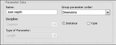
Add a label to this new dimension by selecting it and using the Label drop-down from the Options bar. Name it Joist Depth, choose Dimensions in the Group Parameter Under drop-down list, and make it an Instance parameter.
Click the Types button.
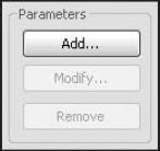
Near the bottom right of the dialog box in the Parameters frame, click the Add button.
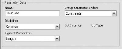
Name the parameter Joist Size, under Type of Parameter choose Length, group it under Constraints, and make it an Instance parameter.
Click OK.
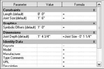
In the Family Types dialog box, give the new Joist Size parameter a value of 1′-6″.
Create a Joist Depth formula, and type Joist Size - 0′ 1 1/4″. Click Apply, and the Joist Depth value should change based on the formula result. You must provide "units" in the formula column; otherwise Revit will interpret the slash (/) as a divide symbol.
Click OK.
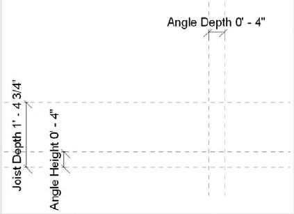
Select the bottom reference plane (the one 1′-4¾″ below the datum).
Select Element Properties
Name the plane Bottom Reference and click OK.
Open the Ref. Level floor plan.
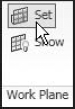
On the Create tab, in the Work Plane panel, click the Set button, set the work plane to Bottom Reference, and click OK.
On the Create tab in the Datum panel, click the Reference Line button (not to be confused with Reference Plane). Draw a reference line from the leftmost reference plane to the rightmost reference plane in line with the Center (Front/Back) origin plane. However, you are not really drawing this one in the same place as the other reference line already in the view; it will be sketched on the bottom reference plane.
Choose a 3D view and verify that there are two reference lines visible.
Flex the family with the Family Types dialog box by changing the Length value to 9′-0″. If both lines stretch, you are good to go. Reset the Length value back to 8′-0″.
Navigate to the Left elevation view.
At this point you can draw some reference planes for the angle. This will only involve adding two additional reference planes, but this is a good time to think about your strategy in more depth. "Should I add more reference planes to provide additional functionality such as angle thickness?" There is no need to do so at this point, but when you are designing a family, always keep this option in mind. More effort will be required as the families become more complex, but the time spent contemplating your strategy will certainly pay off later.
From the Create tab, click the Reference Plane tool using the Pick Existing Line/Edge option, and offset one reference plane 0′-4″ above the bottom reference and the other one 0′-4″ to the right of the vertical origin plane.
Dimension the two new reference planes from the plane you used to create them.
Add a label to the dimension of the horizontal plane, and name it Angle Height. Group it under Dimensions, and make it a Type parameter.
Add a label to the dimension of the vertical plane called Angle Depth. Group it under Dimensions, and make it a Type parameter.
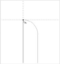
Now you can create the angle sweep. Since you have a reference line to use as the sweep path and two parameters controlling the size, all you need to do is sketch the angle profile.
Open the 3D view.
On the Create tab in the Forms panel choose Solid
On the resulting Sweep tab in the Mode panel, select the Pick Path button. This will bring up a new Sweep
Pick the reference line you just drew along the Center (Front/Back) origin plane. It will be the bottom one of the two. You can freely switch between views in this mode if you need to. In 3D you will see a node with a reference box at the midpoint. Click Finish Path.
This will result in a new Modify Profile tab. In the Edit panel, select the Edit Profile button.
In the Project Browser, open the Left Elevation view. This will allow you to sketch the angle in profile.
Draw the angle using the tools on the Sweep
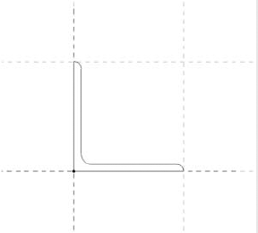
To ensure the angle will be controlled by the reference planes, you will need to align and lock the edges and endpoints to them. At first this may seem somewhat daunting, but once you get the hang of it, you can use this method for many purposes in Revit Structure.
Start by aligning and locking the end of the outside edge of the angle to the family reference plane it stops at. Click the Align button.
For the first alignment point, select the top horizontal reference plane that represents the top of the angle height.
For the second alignment point, select the endpoint of the magenta line representing the back of the angle. When a line's end point is highlighted, the line highlights as well. This allows you to choose the correct end point even though end points from both lines fall on the same point. You may have to use Tab key to cycle through to get the correct one. Once you align the end point to the reference plane, a blue lock icon will appear. Be sure to click this icon, locking the alignment in place.
Because the radial portion needs to be locked too, you need to repeat the process for the endpoint of the arc. That means you basically have to align and lock two endpoints to the same reference plane.
Repeat the procedure for the horizontal leg lines of the angle where it intersects with the Angle Depth reference plane.
To the far right of the Sweep
Again to the far right of the Ribbon, click the Finish Sweep button.
Flex the angle by clicking the Types button and changing the Angle Height and Angle Depth values.
Navigate to a 3D view and flex the Length and Joist Size parameters.
Save the file as
Joist Bridging.rfa.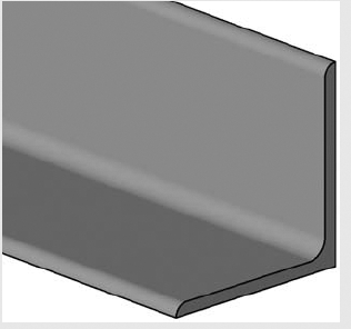
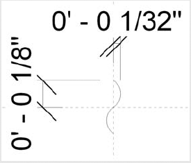
Now it is time to work on the graphical plan representation. In plan view, the symbolic line work will look like the following graphic:
Of course, this plan representation should also adjust to any scale change that may occur as well. To add the break marks at the end of the dashed lines, it would be prudent to make a separate annotation family (because this kind of family will adjust for scale as desired) and load it into this joist bridging family as a component.
From the Application menu, choose New
Select
Generic Annotation.rftas the template and click Open.Read the red block of text and then delete it.
On the Create tab in the Detail panel, click the Line button, and draw the two arcs as illustrated here. You can use the Start-End-Radius arc tool and make them

Save the file as
Tick Mark 1.rfa.Click the Load Into Projects button on the Create tab. Naturally, if you closed the file earlier, you'll need to open it again first.
If you have more than one file open, Revit will ask you which file you want to load the family in; select the
Joist Bridging.rfafile. If your current view is a 3D view in the Joist Bridging family, when you use Load Family you will get the message that Revit "can't create this kind of element in the view in the current mode." The Tick Mark family is annotation, which cannot be used in 3D views. You can ignore the message and move to step 8.In the
Joist Bridging.rfafile, navigate to the Ref. Level plan view.On the Create tab in the Work Plane panel, click the Set button.
Set the current work plane to Level: Ref. Level in the dialog box, and click OK.
On the Detail tab in the Detail panel, click the Symbol button.
Insert the Tick Mark 1 symbol at the intersections of the Center (Front/Back) reference plane and the symbolic offset planes.
Align and lock the symbol both vertically and horizontally to the intersecting reference planes. Remember, select the reference planes first, and then click the symbol's embedded references. When you place your cursor over the symbol, a center line will appear, allowing you to select the symbol reference. You will probably need to use the Tab key to cycle through the possible references. Of course, remember to lock the symbol.
Repeat steps 11 through 13 for the other side.
Open the Family Types dialog box (Type button on the Family Properties panel on all of the Ribbon tabs), and flex the Symbolic Offsets parameter to test the constraints of the newly added symbols.
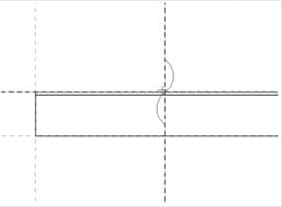
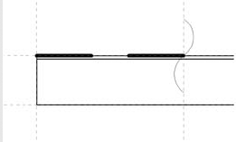
On the Detail tab, click the Symbolic Line button, and then in the Type Selector drop-down (Place Symbolic Lines tab
Draw a symbolic line between the intersections of the reference planes as shown in the graphic below, in which the line weight is exaggerated for clarity. Align and lock these symbolic lines to the reference planes they fall on. Although it is not always necessary to align and lock the endpoints of these lines to the perpendicular planes, it is a good practice to get in the habit of doing so. If you uncheck the Chain option before sketching the lines, you should get the option to lock the padlocks for the endpoints.
Repeat this procedure and draw another symbolic line at the other end. You may need to extend the Center (Front/Back) reference plane if you've increased the Length parameter. If you don't, you may not be able to snap to the intersection of the reference planes until you do. It is also "pinned," so you have to unpin it too.
One last thing to do before you load this family into a project for testing is to prevent the actual angle from being visible in plan view. This will enhance the functionality of the component and decrease the amount of RAM being gobbled up while viewing the plan.
Select the angle in any view.
On the Modify Sweep tab in the Form panel, click the Visibility Settings button.
In the Family Element Visibility Settings dialog box, in the View Specific Display frame, uncheck Plan/RCP. If you wanted to, you could even specify which display levels (Coarse, Medium, or Fine) the angle will be visible in.
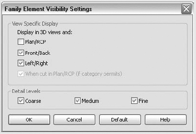
Click OK.
Click the Category and Parameters button in the Family Properties panel.
Change the Family category to Structural Framing. (After you do this, you may notice that Revit Structure changed the symbolic lines to a continuous line type. If so, you can highlight them and change them back to Hidden Lines [Projection]. We could have structured this exercise so that you wouldn't stumble into this issue, but then you wouldn't be aware that it mattered. You should define the category of your family as early as possible to avoid any rework like this.)
Click OK.
Start a new project, and place some 14K joists (or use your project with joists already established).
Load the Joist Bridging family into the new project.
On the Home tab, click the Beam button.
The Joist Bridging family should be the active type.
Click the Element Properties button.
Change the Joist Size value to the appropriate size. (Notice that the other values that were part of a formula in the family are grayed out.)
Place the bridging in plan view. When you first attempt to place the bridging, Revit Structure may default to Place on Face placement, and you'll see your cursor display the "you can't do this" sign, a circle with a slash through it. On the Place Beam tab
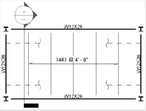
Cut a section along the joist where the bridging is. Vertically, it should fall at the base of the joist right where you want it. The nice thing is you can move the angle into the correct horizontal position in the section, and it will update the placement in plan view as well.
That completes this exercise. How did you do? In this exercise you created a joist bridging family. The family works by being drawn on a framing plan as a single line. As you have seen, the graphical result in the plan view is symbolic line work representation. In section view there is an angle seated on the bottom of the joist for detailing purposes.
The final version of this family and the tick mark symbol family are available for download from this book's website at www.sybex.com/go/masteringrevitstructure2010.
While creating an external family file is a very common practice, there will be times when you need to create a family that requires the surrounding model geometry to construct the family correctly. Or, if the family is so specific that you know it will never be used again, you can create what is called an in-place family.
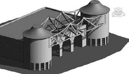
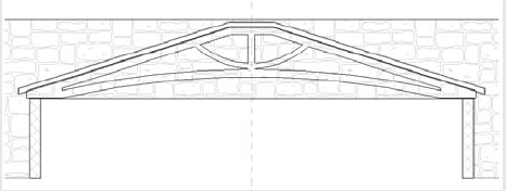
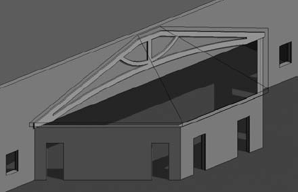
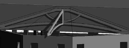
In-place families can be a very powerful tool to help you in the design process. They can also be restrictive if they are created beyond their usefulness. Normally an in-place family is designed to be just what its title implies. Although you can ultimately copy it around the model after it is created, an in-place family depends on specific placement within the model. That being said, if you are planning to create an in-place family, think about how many times it will need to be copied. If you find that you will need multiple instances of the family, creating an external family file (.rfa) may be the way to go. For example, Figure 18.28 shows two roofs and a special truss that was created between them using an in-place family. Because there will likely never be another project that would use these shapes, or any variation of them, it makes more sense to create an in-place family versus an external one.
An in-place family can be used in most situations where a 3D massing type element is required, but what the in-place mass tools produce are general shapes that help with conceptual design. That is the difference between a conceptual mass and an in-place family. When you create a 3D element as an in-place family, Revit Structure then knows that this is the final geometry and is a part of the actual model.
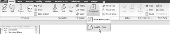
To start an in-place family, the first thing you need to do is go to the Model panel of the Home tab. Click the Component drop-down
The Family Category and Parameters dialog box will open so you can define which category this family should belong to. In this example, you will add a truss to each side of the model.
This is the same Family Category and Parameters dialog box you used earlier when creating the other families in this chapter.
Select Structural Framing as the family category. The next dialog box allows you to name the family.
This is somewhat less important than specifying an accurate family category, but you should always adhere to good naming conventions because the name will be listed in the Project Browser.
For this example, type the name Esthetic Trusses and click OK. Once you have finished naming the new family, Revit Structure will provide a Model In-Place tab similar to what you saw while creating external families earlier in the chapter.
This is done to give you the full capability to create a family just as you would in the Family Editor mode, only this time you can use the existing geometry in the model as a guide—the best of both worlds! Also, you still have access to the Project Browser to navigate to the different project views.
Typically, creating an in-place family will be easier than creating an external family since this type of family usually does not need to be nearly as dynamic as an external family. The dimensions are usually fixed, and the nature of the placement is primarily static. There will be fewer, if any, variable dimensions. In the case of adding a specific item to the side of a building, the only reference planes you may need are the walls, floors, and roofs of the existing structure.
Since you are in the in-place Family Editor mode, you can now add as much 3D geometry as you wish. As we mentioned earlier, however, once you start adding 3D elements, Revit Structure will need you to define a work plane to reference. If the desired location of your in-place family is such that it can be sketched in plan, Revit will know to use the level as the work plane, but other views will require that the work plane be defined. For example, to create a truss profile in an elevation view, choose Solid
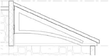
In this example, the face of a wall is being selected as the work plane in which to sketch the special truss, as illustrated in Figure 18.31. You can use most any item as a reference, including established gridlines.
Now you are essentially free to sketch anything you want. If you add reference planes, they will be invisible when you finish the family. If you choose to edit the family at a later date, the reference planes will reappear, as they are embedded in the family itself. Figure 18.32 illustrates an in-place family in production.
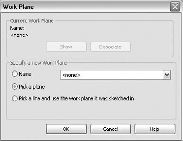
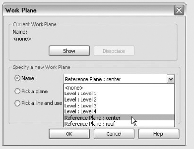
Figure 18.30. The Work Plane dialog box allows you to specify the location on the building where your sketch will reside. It is common to choose a wall or a framing member to establish a work plane.
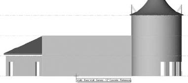
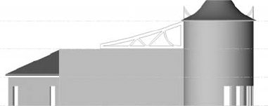
Figure 18.32. This is a sketch of an extrusion within an in-place family. Notice that you can easily draw any shape you need.
Once you have finished sketching the profile, choose Finish Extrusion on the far right of the Ribbon. Notice that when you do that, you are still in the Model In-Place mode. This means you can perform additional 3D functions. This is but one extrusion within the family. Any number of 3D shapes and elements can be included in a single in-place family. In addition, if you look at the Home and Annotate tabs, you will see that you can also insert components and detail components into the family.
To investigate the creation of an in-place family further, you can open the Revit Structure file called Gothic Structure.rvt and follow along with the next exercise.
Exercise: Creating an In-Place Family
This lesson walks you through the creation of a special truss family designed specifically for one building that will never be used again in another project.
Open the file, available at this book's website, called
Gothic Structure.rvt.The file should open by default in the section view called Truss Section - 1. If not, open the view called Truss Section - 1.
On the Home tab in the Model panel, choose Component
For the Family Category value, select Structural Framing and click OK.
For the name, enter Back Entry Truss, and click OK.
On the Model In-Place tab, select Solid
You will encounter the Work Plane dialog box. Under Specify a New Work Plane, choose Pick a Plane, and click OK.
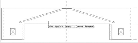
Select the back wall, place your cursor near the boundary edge of the arch opening in the wall, and watch for the tooltip: Walls: Basic Wall: Generic −12″ Concrete : Reference.
Now you are ready to start sketching. Remember, the 3D extrusion will extrude toward you depending on the direction in which the reference plane was created.
Sketch a truss shape, complex or simple—it doesn't matter. It must be a valid sketch, meaning no overlapping boundary lines or segments that fail to close/trim properly.
Click the Extrusion Properties button on the Create Extrusion tab
In the Instance Properties dialog box, verify that the material selected is Wood - Birch.
Set the Extrusion Start value to 0′-0″ and the Extrusion End value to 0′-3″ and click OK.
On the far right of the Create Extrusion tab, click Finish Extrusion.
On the far right of the Ribbon, click Finish Model.
Go to the default 3D view, and rotate the view to check out your truss.
Now you will add a truss in the other direction. Just because you finished the Back Entry Truss family does not mean you cannot edit or continue working on the family at a later time.
Open the section view Truss Section - 2. This will bring you to the side view of the truss you just placed.
Select the truss you previously created, which is under the high point of the back roof against the building. It is only 0′-3″ wide/thick in this view from the side.
On the Modify Structural Framing tab in the Model panel, click the Edit In-Place button. This brings you back into the Model In-Place editing mode, as shown by the current Ribbon tab.
Select Solid
In the Work Plane dialog box, choose to specify a work plane by Name, and select Reference Plane : Center from the drop-down list. We prepared the file for you earlier by adding a reference plane in the plane view and naming it Center.
Sketch another truss profile.
Click the Extrusion Properties button.
Set the End value to 0′-1 1/2″.
Set the Start value to - 0′-1 1/2″ (negative). These two settings place half the truss thickness on either side of the Center reference plane.
Click OK.
Click Finish Extrusion.
Click Finish Model.
Check out the truss in a 3D view.
As you have just seen, you created the trusses while sketching in orthogonal views, which are equivalent to the task of sketching them in a 2D CAD elevation or section once. However, now that you have done this you can study and document the design in any other view that you need because they are 3D trusses, not just 2D line work in a single-view file. The ability to freely create any kind of required geometry in a 2D environment and achieve 3D results is crucial to BIM and the modeling process as a whole. As you can see from the previous exercise, you could easily elaborate on this truss system by adding two section view cuts along the hips and sketching the trusses in those views. Because the additions belong to the same family, you can enjoy greater organization and flexibility if you ever need to alter the trusses.
Another item in Revit Structure that allows for organization is the Group feature. The ability to take any typical geometric configuration and create a unified set of objects from it can be quite powerful.
Families are useful and make Revit Structure effective. Groups extend this usefulness because families are associated with a single category, while a group is a collection of elements that can be associated with a variety of categories. Families also tend to be most effective if they are somewhat ambivalent about the project's specific use of them. Groups, on the other hand, can let you assemble a wide variety of otherwise innocuous families into a very useful, easily repeatable building condition that can be changed efficiently when or if required.
The concept of grouping has been around in Revit Structure for quite some time, and it is a simple procedure. You collect a bunch of components, group them together, and copy the entire group around the model. If you need to change anything within the group, you change one component, and the rest are updated automatically. It is as simple as that. Of course, not every situation will benefit from grouping, but when used correctly it can be very advantageous.
Before you create a group you need to first ask yourself, "Should this be a group?" Like anything in Revit Structure, if you try to use a specific feature beyond its usefulness, you are negating the benefit of that feature's functionality. You can wind up with a collection of groups that get confusing and, worse yet, will exponentially expand your file size. You also have two distinct types of groups: annotation and model. Revit Structure handles model components differently than annotation components, so there are two types of groups available. So with that in mind, let's start creating groups. In our example, a typical cross-bracing elevation will be grouped and then labeled accordingly.
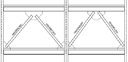
The purpose of a group is to maintain consistency throughout the model by establishing typical conditions and configurations. The end goal, as is the overall end goal of BIM, is to ensure that a change made in one place will occur in every instance of that configuration. There will be times, however, when a copy of a specific group needs to have a stand-alone edit performed. Revit Structure takes this into consideration as well. But first, take a look at Figure 18.33. It is an elevation of two slightly different bracing schemes: Brace Frame A on the left and Brace Frame B on the right. It sure would be nice if these could be grouped and copied around the model. It would be even better if when the HSS sizes change, every instance of Brace Frame A and Brace Frame B would be updated.
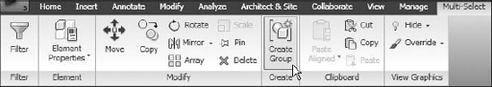
To create the group containing the bracing, you must first select the items you want grouped, including any text and tags. Select the two HSS members, their tags, and the three gusset plates of the left brace frame. A Multi-Select tab is now available.
Click the Create Group button in the Create panel, as shown in Figure 18.34.
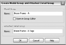
Once you click the Create Group button, a dialog box will appear, allowing you to name two separate items. One item is the model group, which contains all the model components you selected.
Name the model group Brace Frame - A. The second name is for any annotations that go with the components, tags in this case. If you have a group with no annotation, the detail group is omitted.
For this example, name the attached detail group Brace Frame - A Tags, as shown in Figure 18.35.
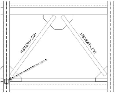
Once the group is created, you will see a blue grip at the bottom center of the group. This is the group origin, and it can be moved.
Place this origin where you want the group's insertion point to be. In this case, it would be a good idea to place it at the intersection of the grid line and the top of the lower framing member. See Figure 18.36.
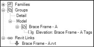
Once the group has been established, it will appear in the Project Browser. Because the group contains model objects, it will appear under the Model heading under Groups. If you expand the model tree, it will expose the Brace Frame - A model group. Now if you expand the Brace Frame - A model group, you will see the attached detail group, indicated by the paperclip icon, as shown in Figure 18.37.
Now that you can see the group in the Project Browser, you can simply drag the group into the model and place it using the insertion point. When you are selecting the group item to drag into the model, be sure to drag the model group, not the attached detail group. Once the model group is placed, you will notice that the tags were not inserted along with it. This is because you may not want to include the annotation with every occurrence of the group. In many cases, you can annotate one typical group and assume the others are the same unless noted otherwise. In the event you do need to annotate each instance, you can annotate the entire group in one shot.
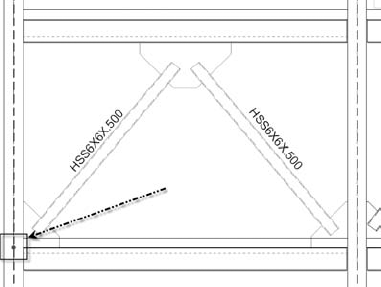
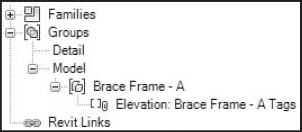
Figure 18.37. The group is displayed in the Project Browser. From here you can simply drag and drop the group into the model.
Once the group has been inserted, select it. You will see that the entire group is one entity with a blue dotted line indicating the perimeter of the group. You will be presented with the Modify Model Groups tab. In the Group panel there are four choices: Edit Group, Ungroup, Link, and Attached Detail Groups.
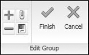
The first choice, Edit Group, allows you to make changes to the group's configuration. Once you click the Edit Group button, you will be using the Group Edit mode. An Edit Group panel will appear on the Ribbon, as shown in Figure 18.38. You can click the plus sign to add elements to the group and the minus sign to remove elements from the group. The paperclip icon allows you to create and attach a new detail group to the model group, and the group properties button will display the group's Instance Properties dialog box. Any changes you make to the group are reflected in every instance of the group that exists in the model.
The Ungroup button removes the grouped elements from the group and returns the geometry to its original state, no longer part of the group. In a sense, using AutoCAD terminology, it "explodes" the group.
The Link option uses the group to create a separate Revit Structure model file, and then that file is linked back into your model. Once you execute this tool, Revit Structure will ask if you want to create a new project file or if you wish to find an existing model, as shown in Figure 18.39. Either way, the instance of the group will be replaced with a linked external file.
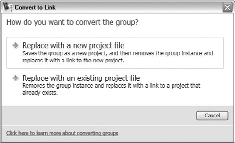
Figure 18.39. You can create a linked Revit Structure model by using the Link option. This can be advantageous in controlling file size.
Normally you will create a new model, but there are some cases such as an architectural overlay where you may want to find an existing model. Once you choose between creating a new model and linking an existing one, Revit Structure will add the link to the Project Browser, as shown in Figure 18.40. You or another team member can now work on the link separately without having to start file sharing. This can become quite helpful in the waning days of a project.
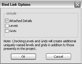
Another nice thing about the ability to turn a group into a linked Revit Structure model is that you can reverse the action. If you select the new link, you will notice a Bind button on the Options bar. You can bind any linked model (it does not have to start out as a group). Once the link is bound, it turns into a group. This can be helpful in many situations, but be aware of the file size of the linked file and what that will mean for the current model's file size once it is bound.
Once you click the Bind button, you will get a dialog box asking which items you want to bring into the current model. See Figure 18.41. If you choose to bring in levels and grids, you will create separate, uniquely named grids and levels. Be careful here, as this could overwhelm you with redundant information. In general, this is probably not a good idea.
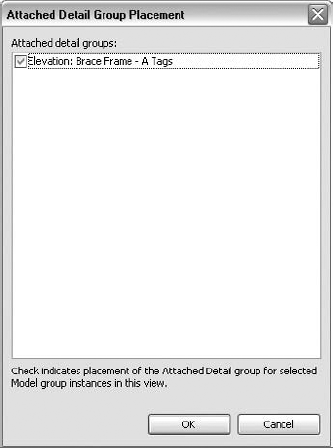
The Attached Detail Groups button will insert the annotations that compose the attached detail group. This is a nice feature that allows you to annotate the model elements consistently. Once you click the Attached Detail Groups button, a dialog box will appear listing the attached details associated with that particular group, as shown in Figure 18.42. You can select a detail, and it will annotate the entire group.
You will almost certainly run into a situation where you would like to make a slight modification to only one instance of a group without having to ungroup the set and create a brand-new grouping. This is allowed in Revit Structure. Once the group has been copied around, you can simply hover your cursor over the object you wish to modify within the group. Of course, the entire group will become highlighted, but once this occurs, press the Tab key on your keyboard to highlight the specific element. While the element is highlighted, right-click on it, and a small group icon will appear along with the shortcut menu, as shown in Figure 18.43. In the shortcut menu you will notice a Move to Project tool and an Exclude tool.
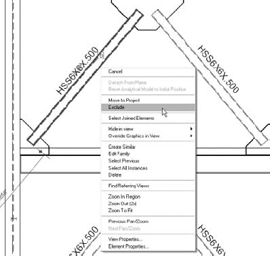
Figure 18.43. By selecting a single element in the group, you can either exclude it from the instance or move it back into the project.
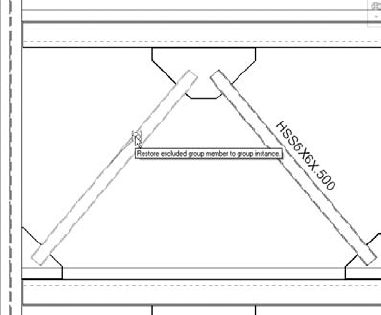
Figure 18.44. By hovering your cursor over a group with an excluded element, you can select the element and click the group icon on the member that was excluded to return it to its original place within the group.
The Move to Project tool will create a copy of the selected element from the group and place it back into the project. The element that this tool is used on is still part of the group, but that same element is now hidden from view (excluded) for that instance of the group, and it won't be included in schedules. In contrast, the Exclude tool just hides the selected element in this instance of the group. You also have the option of clicking the group icon to exclude the element. If you choose to exclude the element from the group, Revit Structure hides it but remembers that instance of the element for later retrieval. After you select Exclude, you can hover your cursor back over the group to reveal hidden elements. After using Tab to select the desired element, you can click the group icon that appears to move the element back into the group, as shown in Figure 18.44. This icon works as a toggle to exclude and restore the selected element. You also have the option of using the shortcut menu and selecting Restore Excluded Member. In addition, if you want to restore all excluded elements, you can select the group as a whole and select Restore All Excluded from the shortcut menu. Keep in mind that should you use the Move to Project tool, the Restore All Excluded tool will make the hidden element visible again, and this will likely mean that there are two elements in exactly the same location. If this does happen, a message will appear warning you that there are now identical instances in the same place.
The following exercise allows you to create a group on your own using the provided Revit Structure model from this book's website.
Exercise: Creating a Brace Frame Group
This exercise allows you to create a brace frame group and copy it throughout the model. As you make your way through this exercise, try to think about specific situations where you may want to use this feature.
Open the file titled
Bracing Groups.rvt.Select all the elements (seven) of the brace frame on the right. This includes the two HSS members, the three plates, and the tags. Be careful not to select the adjacent framing or the slab.
Click the Create Group button.
Name the model group Brace Frame - B.
Name the attached detail group Brace Frame - B Tags. (Note the option Open in Group Editor, which is useful if you need to make some changes right away.)
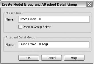
Click OK.
Find the grip dot that indicates the group's insert point of origin, and drag it to the left projected end of the HSS framing.
Expand the Project Browser under the Groups category, and find the new group.
Drag the new group into the bay above.
Select the new group.
Click the Attached Detail Groups button on the Ribbon.
Click the Elevation: Brace Frame - B Tags check box.
You can either repeat this procedure or simply copy the brace frame to each bay. Either way, fill in the rest of the bays above the original Brace Frame - B.
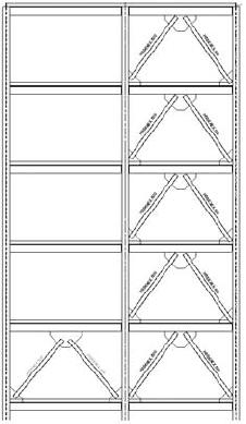
Select any one of the brace groups, and click Edit Group on the Ribbon.
Select the two HSS6X6X.500 brace members, and change them to W8x10s using the Type Selector.
Click Finish on the far right of the Ribbon.
All of the brace members are then updated.
As you can see, there are some real advantages to using groups within a Revit Structure model. Having a good grouping strategy and sharing it with everyone on the team, you will greatly increase your productivity in terms of organization and uniformity.
- Create a footing step family
Creating families is a vital skill. You create a family, such as a footing step family, by meticulously tying reference planes with dimensions and parameters. Then you add 3D solids to the references to achieve a flexible, useful family.
- Master It
When you start a new Revit Structure family from a template, there will be existing reference planes. How do these reference planes help in the creation of the family?
- Create in-place families
You create specialized families, called in-place families, directly within the model, tying the family to the surrounding building. This allows you to more easily create custom geometry that will probably never be used in another model.
- Master It
What is the process for creating a custom family directly within the model?
- Create groups
Adding groups to the model greatly reduces the time spent organizing and manipulating the configuration of certain items. Also, by linking a group, you can actually create a separate Revit Structure model and link it back into Revit Structure, similar to creating an x-ref in AutoCAD.
- Master It
You also learned that a linked Revit Structure file can be turned into an embedded group. Explain the procedure for this to occur.