
For many designers, Flash Catalyst workflows begin in Adobe Illustrator. Illustrator provides a powerful set of drawing tools. These tools allow you to create a comp of your application design that you can later pull into Catalyst and convert into an RIA.
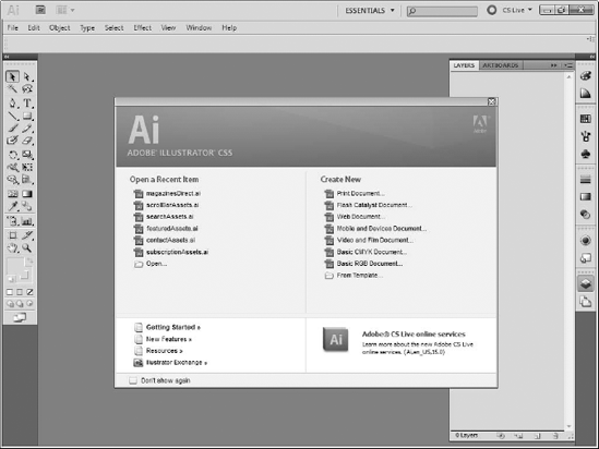
Like other Creative Suite tools, Illustrator displays a Start Screen when first launched (see Figure 5.1). The right side of this screen provides a set of options for new documents. The options provide default settings for your artwork.
Tip
For obvious reasons, designers creating work for Catalyst will usually want to select the Flash Catalyst Document option. There are no significant differences in the initial setup between a Web document and Flash Catalyst document.
You need to establish several basic parameters for your Illustrator document, discussed in the following sections, before you begin. All of these settings will be translated directly into Catalyst, so you need to think about what you want your final application to look like, even at this very early stage of development.
The main difference in Illustrator between selecting a new print document and a new Flash Catalyst document is the color space. Printers have long relied on a color space known as CMYK, so named after the primary colors used: cyan, yellow, magenta, and black.
Note
The K in CMYK is used for black to avoid it being confused with blue.
Computer monitors, like TV sets, color film, and the human eye, use a different model known as RGB, for red, green, and blue. Thus, when you select a new print document, Illustrator uses CMYK, while new Flash Catalyst documents will use RGB (see Figure 5.2).
In many projects, the decision about which color model to use can rely on many factors, but in a Catalyst project, it is quite easy; you are designing an application to be displayed on a computer screen and will thus always use RGB. Therefore, you would never want to click the option to create a new print document.
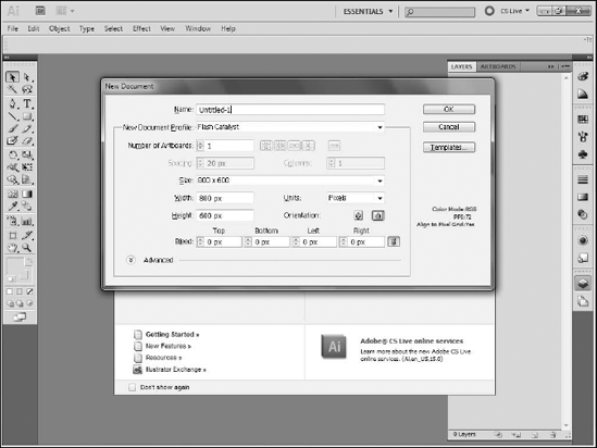
The first option on the dialog box allows you to give the document a name. This name is ultimately used as the file name, so it should be descriptive of the file's purpose.
Next, you need to determine the document size in pixels. As this will translate into the size of your Catalyst project, and ultimately the size of your application, you should set this to whatever dimensions you have chosen for your project. There is no set correct size to use; every application is different and will have different size requirements.
You can either select one of the preset sizes from the drop-down list or type your own pixel dimensions. The units should be left at pixels, while the orientation will automatically change depending on the values input into the Width and Height fields.
Bleed is a term from the print world that allows designers to designate additional space around an artboard to eventually allow printing all the way to the edge of the document. It has no application in Web pages or RIAs, so you can always leave it at its default settings.
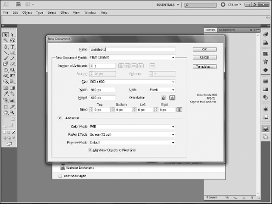
At the bottom of the dialog box, you will see an option to expand the dialog box to display advanced options (see Figure 5.3). These allow you to set the Color Mode, which you should always have as RGB.
The Raster Effects setting determines the resolution at which Illustrator rasterizes effects such as drop shadows. Make sure that this is always set to Screen (72ppi). Finally, set or leave the Preview Mode at Default.
As its name implies, the main idea behind Illustrator is drawing. It has a powerful set of tools that allow you to create vector-based artwork.
Illustrator's Tools panel runs down the left edge of the screen (see Figure 5.4). Tools are organized into categories, grouping them together based on their main functions.
The top section of the Tools panel contains the selection tools. The black arrow represents the Selection tool. Any time you need to simply select an object on the artboard, whether to move it, delete it, group it with other objects, or change its properties, you can use the Selection tool.
The white arrow is the Direct Select tool. All objects drawn in Illustrator are made up of vectors. The Direct Select tool allows you to select portions of a vector drawing. For example, you can use the Direct Select tool to select a single line within a shape.
Note
For more information on vector artwork, see Chapter 3.
Many of the tools on the Tools panel have a small arrow in the bottom-right corner that indicates that there are multiple tools grouped together. You can access the additional tools by pressing and holding your mouse down on the tool.
The Direct Select tool is the first example of this. Press and hold your mouse on the Direct Select tool to reveal the Group Selection tool. Despite its name, the Group Selection tool does not select groups of objects. Instead, it does the opposite: When you have a set of objects grouped together, the Group Selection tool allows you to select individual items within the group.
The Magic Wand tool, immediately below the Selection tool, allows you to select objects based on similar characteristics. For example, it can select all objects that have the same color fill or stroke.
To its right is the Lasso tool, which allows you to draw a free-form selection around an area of the stage. Any items that fall within the selection form, in whole or in part, are selected.
You will find that you need to use a combination of these tools frequently in any project. Taking some time to become familiar with these tools will pay dividends down the road.
The bulk of Illustrator's tools are for drawing. Before you begin drawing in Illustrator, keep in mind that everything you draw is a vector. While Illustrator can import raster art, it does not create it.
Drawing in vectors can take some getting used to, as it often requires techniques that are different from drawing raster art. However, you will likely find that once you are familiar with the tools, you can generally draw much more precise shapes and lines with vectors than rasters.
The primary tool used for drawing in Illustrator is the Pen tool (see Figure 5.5). All vector art is made up of anchor points that connect line segments or paths. When using the Pen tool, you are simply defining these anchor points, while allowing Illustrator to draw the connecting paths.
Drawing a straight line is fairly simple with the Pen tool. Simply click at a point where you want the line to begin, and then click again where the line should end. After you draw the second point, Illustrator draws the connecting line.
Tip
When using the Pen tool, you do not click and drag to trace the line you want to create. Remember, that you do not draw the lines themselves with the pen; instead, you define the points that make up the lines.
Once you create the second anchor and have a line, any further clicks on the artboard create additional anchor points and new lines in the same shape (see Figure 5.6). If you eventually click back on your original point, you close the paths and create a single, closed shape that can then be filled.


Figure 5.6. Creating a closed shape by clicking on the original point after creating a series of paths
Tip
Pay attention to the indicator icon in the bottom right-corner of the Pen while moving around the art-board. An X indicates that you are about to start a new series of paths, while a closed circle indicates that you are over your original point and are about to close the path. Whenever you see the Pen tool with no icon in the corner, you are going to add to the existing shape.
If you want to start a new shape, you need to reset the Pen tool. Clicking on your original point to create a closed path accomplishes this.
However, if you want to leave a path open and simply start a new shape, you can simply click on the art board while holding down the Ctrl (
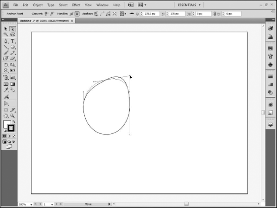
You can also use the Pen tool to create curves (see Figure 5.7).
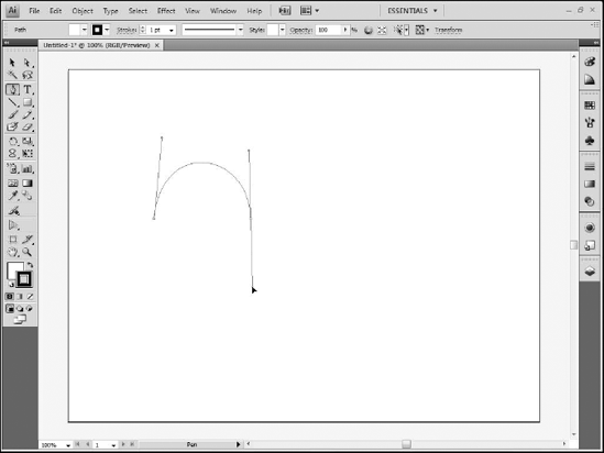
Curves require that you click and drag with your mouse, but just as with straight paths, you are not tracing the actual curve you want to create. You still need to define anchor points, regardless of whether those points are defining curves or straight paths.
Straight path anchor points are only the anchor. Curves require both the anchor point, from which the curve originates, and a pair of control handles. The handles define the height and arc of the curve.
Therefore, when you define a curve anchor point, you click and drag to create one of these control handles. The other handle, which mirrors the first, is created for you. Your first control handle should be in the general direction you want your curve to go. If you want to create a curve that goes up from the point, drag up.
After you create the first control handle, release your mouse button and move to the point on the artboard where you want to place your second anchor point. This defines the end of the curve.
Here again, you click and drag to create your control handles. However, you need to drag in the opposite direction from your first control handle. If you dragged up for the first handle, you drag down for the second. The angle at which you drag determines the arc of the curve, while the distance you drag sets its height.
As with straight segments, you can continue creating additional curves on the path by clicking and dragging from new places. You can also return to your original point to close the shape.
One of the nicest features of drawing vectors is that they remain editable at all times. If your first attempt at drawing a path is not exactly what you want, you can simply modify it until it looks the way you need it to.
The Direct Select tool is most often used to modify paths (see Figure 5.8). You can use it to move a straight line segment's anchor point to a new location, thus adjusting the path. You can also use it to modify curves. Moving the curved segment's anchor point adjusts it, but you can also move the control handles to further fine-tune the path.
Straight segments and curve segments can be combined to create complex shapes (see Figure 5.9). The only difference between a straight segment's anchor point and a curved segment's anchor is the lack or presence of control handles.
Therefore, you can convert straight-segment anchors into curve anchors by adding handles, and you can change curves to straight anchors by removing them. These modifications can be done with the Pen tool and a modifier key on the keyboard or with specific tools.

To create a path that combines straight lines and curves, follow these steps:
Ctrl+click (

Click on the artboard to create a straight-line anchor.
Click on another location to create a second straight anchor.
While pressing and holding the Alt (Option) key, click and drag from the anchor point created in Step 2 to add control handles to it.
Move your mouse to a new location. Without holding any keys on the keyboard, click and drag to create a new curve anchor point.
Press and hold the Alt (Option) key, and click on the anchor point created in Step 4. The control handle that matches the direction of the curve remains, but its opposite handle is deleted.
Click in a new location on the artboard to create a new straight anchor point.

You can repeat these steps as often as needed to create complex artwork.
You can achieve the same technique by switching between the Pen tool and the Convert Anchor Point tool, which you can access by pressing and holding your mouse on the Pen tool in the Tools panel. However, it is much faster and easier to remember the keyboard modifier, rather than switching tools.
Sometimes, you need two consecutive curves that go in the same direction, creating a series of bumps. The problem is that when you click and drag to create the second anchor point, finishing your first curve, you are creating the first control handle for the next curve. Unfortunately, this handle is going in the wrong direction. This creates a series of flowing curves (see Figure 5.10) but does not allow you to have each curve mirror the prior curve.
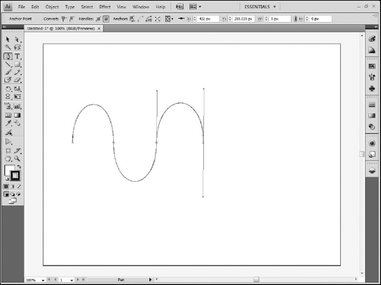
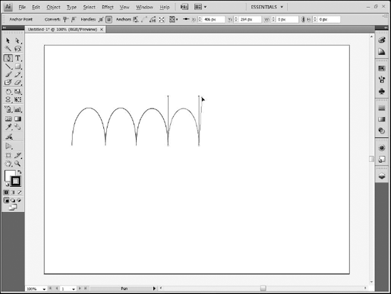
In order to get the second curve to match the first, you must change the direction of that second control handle after you draw it. You can do that using the same keyboard modifier you used to combine straight and curve line segments. To create a series of matching curves, as seen in Figure 5.11, follow these steps:
Ctrl+click (
Click and drag on the art board to create an anchor point and control handles.
Click and drag in a new location to create a second anchor point, its control handles, and the curve path.
Press and hold the Alt (Option) key on your keyboard and position your mouse over the end of the second control handle.
While still holding down the key on the keyboard, drag the handle to a new location.
Release the key, move to a new location on the art board, and click and drag to create a new anchor point, control handles, and path.
These steps can be repeated to create a series of matching curves. You can adjust and fine-tune the curves later with the Direct Select tool.
While you can draw almost any complex shape manually using the Pen tool, Illustrator provides a set of shape tools to simplify the process of creating common shapes (see Table 5.1).
Table 5.1. Illustrator Shape Tools
Tool | Description | Notes |
|---|---|---|
Rectangle | Draws a simple rectangle | Press and hold the Shift key while you draw to create a square. |
Rounded Rectangle | Draws a rectangle with rounded corners | Hold the mouse while drawing a rounded rectangle. Press the Up and Down arrow keys to increase or decrease the amount of roundedness of the corners. As with the rectangle, holding the Shift key while you draw creates a rounded square. |
Draws ovals and circles | Press and hold the Shift key while you draw to create a perfect circle. | |
Polygon | Draws multisided shapes | While drawing, press the Up arrow key to increase the number of sides, and the Down arrow key to reduce the number of sides. You can rotate the shape by moving your mouse left or right while you draw or press and hold the Shift key while drawing to lock one corner at the top of the shape and prevent it from rotating. |
Star | Draws stars | While drawing, press the Up and Down arrow keys to increase or decrease the number of points. You can rotate the star by moving your mouse left or right while you draw or press and hold the Shift key to lock the one point at the top of the star and prevent it from rotating. |
Flare | Creates a flare or starburst effect | Drawing flares requires two steps. First, click and drag to create the center and halo part of the flare. Then click in another area of the art board to create additional rings radiating from the center point. While drawing the first part, use the Up and Down arrows keys to increase or decrease the number of rays. While drawing the second, use the Up and Down arrow keys to increase or decrease the number of additional rings. Press and hold the Shift key while drawing the first part to prevent it from rotating. |
All of the tools are grouped together in one place on the Tools panel, so you need to click and hold your mouse on the Rectangle tool (see Figure 5.12) to access them.
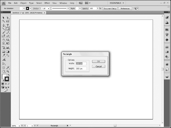
If you want to create a shape with precise dimensions, follow these steps:
Select the Shape tool and click once on the artboard. A dialog box appears.
Enter the desired parameters. The dialog box for rectangles and ellipses lets you set the width and height of:
Rounded rectangles, the width, height, and corner radius
Polygons, the radius and number of sides
Stars, the inner and outer radii and number of sides
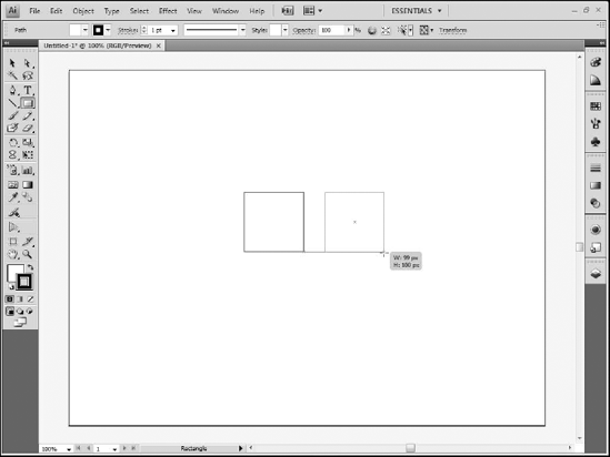
While you draw a shape, light green lines called Smart Guides appear on the artboard. Smart Guides help you align new shapes with existing objects on the artboard. By default, your new shape attempts to snap to these guides. You can disable Smart Guides by choosing View
Similarly, a small tooltip appears in the bottom-right corner of your shape while you draw that displays the width and height of the shape, providing a reference to allow you to draw shapes at a given size (see Figure 5.13).
The Paintbrush tool allows you to draw on the artboard using more traditional techniques than those provided by the Pen tool. After you select the tool, the Control panel along the top of the screen updates to show the tool's properties. You can select the stroke color from the Color Picker. You are always painting strokes with the Paintbrush, so even though the Control panel displays Color Pickers for both the fill and stroke, only the stroke will have any effect.
Tip
Clicking on the Color Picker displays a list of the color swatches in Illustrator. You can also hold down the Shift key while you click to produce an alternate Color Picker interface that displays red, green, and blue sliders.
You can set the width of the stroke by either selecting a preset value from the Stroke drop-down list or typing a value in the text box. You can click directly on the Stroke label to display a panel that provides you with many additional stroke properties.
The drop-down list to the right of the Stroke settings allows you to pick a brush profile, which affects the appearance of the stroke around curves. To the right of the Stroke settings drop-down list is another list from which you can select one of several brush presets. At the bottom of this selection is a button that displays a menu of additional brush types. Finally, the style and opacity settings allow you to apply preset styles or change the transparency of the stroke.
Note
See Illustrator CS5 Bible, by Ted Alspach, for more detailed information on brushes, presets, and styles.
The Eraser tool allows you to erase any objects you have drawn on the artboard. You can increase the size of the eraser by pressing the left square bracket key ([) or decrease it with the right square bracket key (]).
Note
Technically, the Eraser tool does not erase, but redraws the outlines of shapes into new compound shapes. Therefore, if you erase inside a shape that has a stroke, you will notice that its stroke appears around the edges of whatever area you erased. This also means that the erased area can be altered or basically redrawn using the Direct Select tool.
In addition to its drawing tools, Illustrator provides a set of tools that allows you to modify your artwork after you draw it.
The Direct Select tool's primary purpose is to modify vector art after it has been drawn (see Figure 5.14). Vector shapes are made up of paths connected to anchor points. You can adjust these anchor points with the Direct Select tool whenever you need to change the art.
When you first click on an object with the tool, all of its anchor points become selected. If you then click on a single anchor, it remains selected while the rest are deselected. Selected anchor points display as solid, filled squares, while deselected anchors appear as open squares.
Anchor points are either for straight segments or curves. Straight anchor points do not have control handles. If you select one with the Direct Select tool, you can reposition it on the artboard, which causes the line segments attached to it to reposition as well. If you select a curve anchor point, you can reposition it, but you can also click and drag on either control handle to modify the curve.
Tip
Curve anchor points have two handles that are linked to one another, so moving one handle moves the other in the opposite direction. If you need to move only one handle, you can press and hold the Alt (Option) key while you drag. This breaks the connection between the handles and allows them to move independently. Once the link is been broken, you can continue to adjust either handle without holding down the modifier key.
You can also click and drag line segments with the Direct Select tool. Dragging a straight segment moves it and necessarily adjusts segments directly adjacent to the one being moved, but leaves the other anchor points on the shape in place. Dragging a curve segment has much the same effect as dragging its control handles.
Tip
You can select more than one anchor point by holding down the Shift key and then clicking additional points.
Almost all objects in Illustrator are made up of two parts: a fill and a stroke. Each object can have its own color. The program provides several places to set these colors, but all have the same ultimate effect so you can use whichever one you prefer.
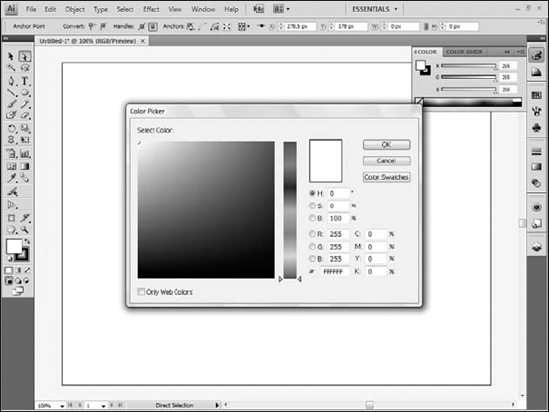
The Tools panel contains a fill and stroke color setting toward the bottom. These are two large squares, one filled and the other just an outline. The filled square represents the fill color, while the outline is the stroke. You can change the color of either by double-clicking it, which displays the Color Picker dialog box (see Figure 5.15).
You can also select colors for either the fill or the stroke using the Color, Color Guide, and Swatches panels. All are normally available from the panel sets on the right side of the screen, but if you don't see them, they can also be accessed from the Window menu.
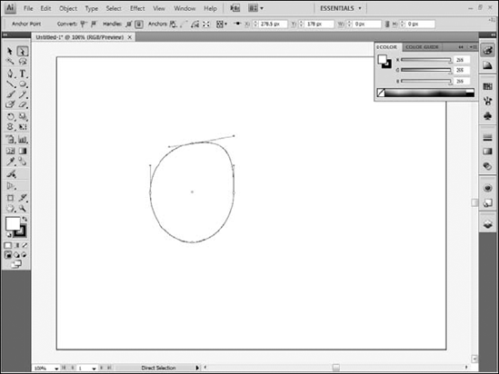
The Color panel (see Figure 5.16) provides three sliders, one each for the red, green and blue in the color, along with a color spectrum along the bottom of the panel. You can select whether you are setting the fill or the stroke in the top-left corner of the panel.
The Color Guide panel displays a set of color groups (see Figure 5.17). Once you select a group, you can choose from a variety of related tints. The panel does not provide an icon with which you can select whether you are creating a fill or stroke color. Instead, you need to click the appropriate button on the Tools panel.
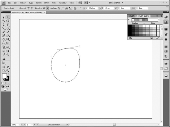
The small icon in the bottom-right corner of the Color Guide panel allows you to choose from a set of swatches upon which the guide's groups are based.
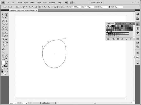
The Swatches panel provides a set of predefined colors (see Figure 5.18). Like the Color Guide panel, it doesn't have an icon to set whether you are applying the swatch to a fill or a stroke, so once again you need to use the Tools panel's button.
The Swatches panel also provides a menu in its bottom-left corner from which you can choose from a variety of additional panels, each of which opens as its own separate panel. You can add swatches from these individual panels to the main Swatches panel by simply dragging the swatch from the new panel to the Swatches panel.
Warning
Most of the swatches in the additional panels use CMYK, so be aware that these colors may look different once they are applied to Catalyst and converted to RGB.
Once selected, you can use the current stroke color with any tool that draws strokes, such as the Pen or Paintbrush. Shapes use both the current fill and current stroke color.
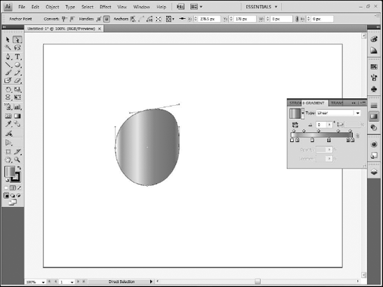
Gradients are a gradual shift from one color to another over the course of a fill or stroke. Illustrator includes the ability to define custom gradients and use them as an object's fill or stroke.
The Gradient panel allows you to create gradients (see Figure 5.19). Illustrator supports both linear and radial gradients. The Gradient panel displays a gradient ramp that shows the current gradient and allows you to define the colors to be used. Each color is called a color stop and is represented by a small box with an arrow just below the ramp.
You can change the color of any color stop by simply double-clicking its box. This displays a pop-up panel that allows you to set any color you want by dragging sliders.
Note
The default gradient in Illustrator is a linear gradient from white to black. When you first attempt to modify the color stops, the Color Picker only displays a single slider for shades of black. You can either click the Swatches button in the top-left corner of the pop-up to use a swatch, or click on the panel menu — the button in the top-right corner — and switch from Grayscale to RGB.
You can add more color stops by clicking in the area immediately below the gradient ramp. Should you inadvertently add a color stop and decide you no longer need it, you can remove it by simply dragging it straight down, away from the ramp.
You can drag each color stop left or right to change its position within the gradient. Color stops can be duplicated by Alt (Option)-dragging them. You can reverse the entire gradient by Alt (Option)-dragging either the left-most or right-most stop to its opposite side.
You can save a custom gradient by placing it in the Swatches panel. To do this, simply drag it from the large Gradient Fill button at the top of the Gradient panel to the Swatches panel.
Once a gradient is applied to an object, you can use the Gradient tool to modify it. Clicking on an object on the artboard that contains a gradient displays a gradient ramp for that object. You can drag the circle at one end of the ramp to reposition the gradient within the object, or drag the square at the ramp's opposite end to resize it.
The ramp also displays each color stop, so you can adjust their positions within the gradient and even double-click them to change the colors. You can use the Gradient tool to redraw a gradient within a shape that already has the gradient applied by clicking and dragging inside the shape.
Illustrator's Transform tools allow you to rotate, reflect, scale, and shear objects.
The Rotate tool allows you to spin an object around an arbitrary anchor point. By default, the anchor will be in the center of the object, so you can simply click and drag to rotate the shape. You can also click with the tool to reset the anchor point — the point around which the object will rotate — at any time. The anchor point doesn't need to be within the object itself.
Note
In order to use the Rotate tool, you must first select the object you want to rotate with either the Selection or Direct Select tool.
The Reflect tool allows you to flip an object over an invisible axis. To use it, follow these steps:
Select the object, using either the Selection or Direct Select tools.
Select the Reflect tool.
Click on any point on the art board to define the first point in the invisible axis.
Click on a second point, defining the end of the axis.
Once you click on the second point, the object flips over the axis line. If you want to create a mirrored copy of the object, hold down the Alt (Option) key when you click on the second point.
Warning
If you use the Direct Select tool, be sure to select the entire object. If you only have some of the shape's anchor points selected, only those points will be reflected.
The Scale tool allows you to resize objects. You can use it to click and drag over either an anchor point or a line segment on a selected object and resize that object. If you want to maintain the object's proportions, press and hold the Shift key while dragging.
You can skew or shear an object along an axis using the Shear tool, which is grouped with the Scale tool. The object will be sheared relative to its axis point when you drag from either a path or anchor point. The axis point is represented by a small cross hair and by default in the center of the shape. You can drag this axis point to any other spot, inside or outside of the shape, to change this axis point.
The Free Transform tool combines the functionality of the Rotate and Scale tools. When you click on an object with the Free Transform tool, you can click and drag just outside the object to rotate it or drag any of the white control handles around the selection outline to resize.
You can also drag anywhere inside the object to reposition it. Unlike the Rotate and Scale tools, the Free Transform tool does not allow you to change the axis around which the object rotates or from which it scales.
Illustrator allows you to organize your complex drawings into layers, sublayers, and groups. It might be easiest to think of drawing in Illustrator as analogous to drawing on clear sheets of plastic overlaid on one another. Each sheet is a sublayer in Illustrator. Each time you add a new object, Illustrator automatically creates a new sublayer on top of those that already exist.
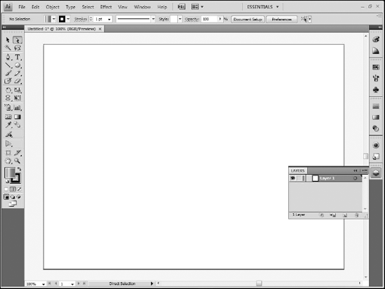
You can see this represented on the artboard; when you draw an object that overlaps those you have already drawn, the new object appears on top of the others. All layers and sublayers are shown in the Layers panel (see Figure 5.20).
Sublayers contain the actual artwork in your Illustrator drawing. You can group sublayers that contain similar or related artwork into layers for better organization.
When you first create an Illustrator file, the program automatically creates a single layer. Any objects you add to the file are placed on sublayers within this layer. However, in larger projects you will want to create additional layers, give them meaningful names, and place sublayers within them.
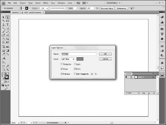
You can rename a layer by simply double-clicking its name in the Layers panel. This displays the Layer Options dialog box (see Figure 5.21). You should always give layers meaningful names based on their content.
The Layer Options dialog box also allows you to set a color for the layer. The selection box around objects on the layer is in this color, providing an easy way to tell which objects are on which layer.
Click the small arrow to the left of the layer name to expand it and show its sublayers (see Figure 5.22). You can and often should rename sublayers. The procedure is the same:
Double-click the sublayer's name.
Type a new name. Any new objects are created as sublayers of the currently selected layer, so be careful to select the appropriate layer as you draw.
You can create new layers by clicking the New Layer button at the bottom of the Layers panel. If you want to rename the layer as you create it, press and hold the Alt (Option) key while you click the New Layer button to immediately display the Layer Options dialog box.
Click and drag a sublayer to move it from one layer to another. The order of the layers and sublayers in the Layers panel is the visual stacking order of objects on the artboard. Click and drag layers or sublayers to rearrange them to create a different stacking order.
The small circle to the right of the layer or sublayer name allows you to select the object or objects on the layer. This can be particularly helpful if you need to select an object that is visually behind other objects on the artboard. Simply click the circle for that layer or sublayer, and Illustrator selects the relevant objects on the artboard.
The eyeball icon to the left of the layer name allows you to show or hide the objects on the layer. Clicking the icon for a layer shows or hides all of its sublayers, but each sublayer has its own visibility icon as well.
The empty box to the right of the eye visibility icon allows you to lock a layer or sublayer. Once locked, the objects on the layer cannot be selected or modified in any way. As with visibility, you can lock a layer and thus lock all of its sublayers, or you can lock individual sublayers as needed.
You can add text to enhance your artwork in Illustrator. The program includes a set of text tools for typing horizontal or vertical text, text within shapes, and text on a path.
With the basic Text tool, you can click on the artboard and simply begin typing. The Control panel at the top of the screen displays common text properties, including font, style, size, and color.
You can click on the Character label in the Control panel to display the Character panel with additional text properties or the Paragraph label to display the Paragraph panel. Text, like other objects in Illustrator, can have both a fill and a stroke.
The Area Text tool allows you to add text to an existing shape or object. Almost any path you create can be converted into a text box with this tool. Simply click on the path to add text. You will lose any strokes or fills you have applied to the shape.
The Type on a Path tool allows you to type text that follows a path, most often one drawn with the Pen tool. Once typed, you can adjust the text's position along the path, as well as changing the path itself. The Vertical Text, Vertical Area Type, and Vertical Type on a Path tools all behave similarly to their horizontal counterparts.
You can use effects to add more visual impact to your design. Illustrator contains a set of effects unique to it as well as Photoshop's Filters, providing you with a variety of effects to apply (see Figure 5.23).
All of the effects are in the Effects menu. You will need to select an object on the art board and then select the appropriate effect from the menu. Each effect displays a dialog box. Select the Preview check box to see the effect on the art board as you adjust its settings.
Once applied, effects can be modified using the Appearance panel. This panel can be opened by choosing Window
Beginning in Illustrator CS4, designers could divide their work across multiple artboards. A print designer might create a brochure and want to design the front cover, inner pages, and back cover in Illustrator, and so could put each page on a separate artboard.
Web applications rely on a similar multi-page construction. An e-commerce application, for instance, would have a page with a product list, another page with product details, and then several pages to display the shopping cart and checkout process. Almost every project you create for use in Catalyst is likely going to need more than one page. When creating the comp in Illustrator, you can either create the designs for these multiple pages as layers which can be turned on and off as needed, or you can create them on separate artboards. The advantage to the latter approach is that these artboards will be automatically converted into pages upon import into Catalyst.
Note
See Chapter 10 for more information on pages in Catalyst.
The preceding sections have served as a general overview of Illustrator. Much of the work you will do in Illustrator will be the same, regardless of whether you bring that artwork into Catalyst or are designing with something else in mind. There are, however, some things you need to take into account to make the transition to Catalyst easier.
Illustrator files frequently contain dozens and sometimes hundreds of layers and sublayers. All of these layers and sublayers are imported into Catalyst and appear in its Layers panel. Therefore, taking the time as you design in Illustrator to ensure that your file's layers and sublayers are well organized will save time once you import the project into Catalyst.
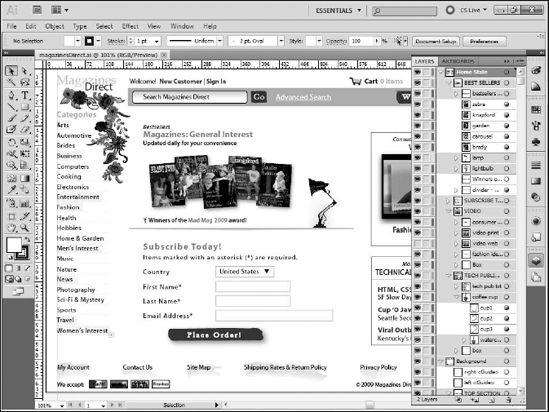
Catalyst projects contain a series of application states. These are roughly the equivalent of pages in a traditional HTML-based Web site. For example, an e-commerce Web site will likely have a home page, catalog page, and shopping cart page. The same site as a Flex project will have a home state, catalog state, and shopping cart state.
Each of these states needs to be represented in your Illustrator project. You can simplify your work in Catalyst by grouping all of the assets for each state together in single layers, with shared components such as a logo or main navigation in its own layer.
Every layer and sublayer in Illustrator should have a logical name describing its purpose in the application. Eventually, a Flex developer is likely to take on the task of finalizing the project, and the names you choose early on in Illustrator will be used by the developer in Flash Builder. Therefore, you need to follow a consistent naming convention. Adobe has yet to develop any guidelines on naming best practices for Catalyst comps, so you should instead discuss the issue with your Flex developer and decide on a convention that you can both use.
If you choose to import graphics into Illustrator to use as part of your design, you can choose to embed the graphics directly into your project or link to them as external resources. When designing in Illustrator for print, there are advantages to linking, but in Catalyst, linking to those files can be problematic. If you later pass on your project to a Flex developer, the Developer may be unable to access those files as the paths will have changed. Therefore, you should embed all assets.
Tip
If you import raster graphics, be sure to choose Object
Typical designs will have many repeated assets. You may have a navigation bar that contains repeating backgrounds for buttons or a planned fillable form with repeated boxes representing the backgrounds of the form fields.
While standard practice in Illustrator is to simply copy these assets, Catalyst contains the ability to take an object, convert it to a component, and reuse that component as often as needed. In fact, you will want to avoid repeatedly defining components for artwork that is the same, as it needlessly bloats the file size of the final Flex project and makes updating and maintaining the application more difficult. Therefore, mark any assets that you are copying in Illustrator to make it clear that they do not need to be redefined.
One easy way to do this is to use a consistent name for these assets. For example, the initial box for a form field might be TextField_Background, while duplicates might be Dup_TextField_Background.
A common practice among Illustrator designers is to convert text to outlines. This process changes the text from editable type into vector shapes and is often done when creating works that will be sent out to a commercial printer. If the printer doesn't have the font the designer used, the printer will be unable to produce the document, so converting to outlines removes that as a possibility.
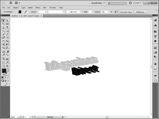
Catalyst projects automatically embed fonts except for common system fonts such as Arial. Therefore, you don't generally need to worry about converting text to outlines. One exception is that Catalyst doesn't always correctly import text that has filters or effects, such as glows or drop shadows. Therefore, this text should be converted to outlines so that it looks correct in Catalyst. Keep in mind that this text will not be editable as text in Catalyst.
The other time you should consider creating outlines for text is when you have small blocks of text that use an uncommon font. For example, if your organization's logo needs to be rendered in a particular typeface, and that font will only be used for that logo, then you can save file size on your final project by converting that text to outlines so that that font is not embedded into the project.
You might consider doing the same to other small blocks of text that will remain as static text in the final project, but keep in mind that you lose the ability to edit that text without going all the way back to Illustrator.
Artwork drawn with Illustrator's Art and Pattern brushes will be converted into vector paths upon import into Catalyst. Each stroke drawn with these brushes becomes an individual path, which can result in hundreds or even thousands of paths, each of which needs to be treated as an separate object in Catalyst. Illustrator CS5's new Blob brush, however, automatically combines paths as you draw with it. In one example from the project created for this book, a line drawn with the Pattern brush was imported into Catalyst as forty paths; when redrawn with the Blob brush, it imported as a single path.
This chapter served as an introduction to Illustrator. For many designers, Illustrator will be the starting point for work in Catalyst. Most likely Catalyst will be the tool of choice for the creation of the initial design comp that is later converted into a Catalyst project.
You learned the following:
How to create a new document in Illustrator
How to use many of Illustrator's tools for drawing shapes and objects
How to organize your artwork into layers
How to use text in your designs
How to apply filters and effects to layers
Best practices to follow in your design