
Chapter 8. Physical Input
Interaction design opens new possibilities of interaction between humans and technology. Physical computing is a particular type of interaction design that centers on the interaction between the human body and the computer. All the types of interaction explored in this chapter are driven by physical actions, both the sending of information out into the physical world and the sending of information from the physical world into the digital world. The power of physical interaction is in the connection of a physical action to an abstracted result, be that an auditory or visual result.
Some of the controls explored in this chapter are instantly familiar, such as knobs, buttons, and sliders, and some aren’t so instantly familiar, such as accelerometers and infrared sensors. All the code will be Arduino, and we’ll include diagrams to help you get your components connected to your board.
Interacting with Physical Controls
Human beings are flat perceivers; that is, we perceive the world as a flat 2D space. This is advantageous, evolutionarily speaking, because it’s a natural limit to the amount of information humans can accept. However, humans are quite skilled at mentally manipulating a series of two-dimensional images into a fully realized three-dimensional space, assembling it piece by piece. To record information, we are quite accustomed to drawing flat representations, maps, and diagrams, with which a three-dimensional mental model can be mentally assembled. The classic way of turning two-dimensional information into three-dimensional information is to physically manipulate the object or environment. You want to see how it fits together, so you turn it over; you want to see the other side, so you walk around it. This physicality is an inseparable aspect of information gathering, and as anyone who has spent time interacting with alternative interfaces like a multitouch user interface or any other kind of haptic interface can attest, varying the physical interaction frequently leads to new experiences, new realizations, and new ways of thinking.
One of the great strengths of using physical interaction is the ability to separate the feedback from the action that the user takes. Anyone who has spent time making music can relate to the intuitiveness of turning knobs to speed or slow a beat or change a pitch. We have tools that help us physically and cognitively understand and work with an interface using physical objects that we manipulate with our hands.
In the simplest model of physical input: you press a button, and a light goes on. In a more complex model, you tilt and turn a sensor, and the tone a computer plays changes; you turn a pair of dials, and a camera pans and rotates. What these all have in common, of course, is that they’re physically driven by controls that are instantly recognizable as controls. In this chapter, we’ll focus on such controls. An entirely separate realm of physical computing uses implicit interfaces and focuses on gathering physical or environment data in ways that aren’t directly controlled by the user, and we’ll cover some of those later in this book. When you think about an explicit interface, you’re dealing with quite different challenges than when you’re dealing with an implicit interface.
All controls require some discovery to use—some instruction given to us by a combination of the controls and the labels around the controls. With anything that we make for others to use or that we ourselves learn to use, the creator must provide a discovery process that the participant actively takes part in. When we are faced with a new control or a new series of controls, those controls have unknown consequences and side effects. To understand those consequences and side effects, we have to discover how to work the equipment. How we approach engendering this discovery process, and specifically, how we engineer the discoverability of an object, is one of the most important decisions in making an application or device.
Any equipment that we interact with via controls has three elements to it: the things that we touch, the electricity that powers and communicates with the system, and the software that handles that communication. While you as the developer and creator will, of course, be concerned with all three, you have to remember that the user will deal only with the first.
Thinking About Kinetics
Here’s an interesting question: is kinetic motion thinking? Well, yes. To paraphrase the psychologist Scott Kelso, it’s important to remember that the brain and the mind that it engenders didn’t evolve just to picture and analyze the world. The brain and mind are both parts of a larger system that always exists within a physical realm. A lot of research suggests that the ways in which humans think is an extension of their existence as embodied minds. The way that we think is driven by our physicality, and our physicality drives the way that we think. Your goal in interaction design is to tailor the design of your application to your users’ capabilities and to the way that they process information and make decisions—in short, to the way that they think. Interacting with physical controls allows users to act and react kinetically.
We’ve all seen muscle memory in action, abstractly. An experienced guitarist isn’t consciously aware of each finger. They see through the action to the task. In a sense, this is the goal of industrial interaction design: to allow workers to perform their action instinctively and without the need to consider each action but to instead consider its larger consequence. A task itself is often an impediment to seeing through it to the desired result. Most often when making an interactive system, the goal should be enabling the user to realize a goal or see through the interaction to the system below it. When we speak or listen to our native language, we don’t have to actively think to process and produce the information. Physical interaction is much the same; we’re adept with our hands, and we learn certain movements quickly and well enough that we can perform them before our conscious mind is fully aware of what we are doing. Tapping into this fundamental human ability lets your users engage your system more fully and develop habits around that system more quickly.
Muscle memory is more than the movement of the body. Many linguists have noted how native Chinese speakers frequently “write characters in the air” with their fingers when attempting to recall the stroke order for a particular character. This is a linguistic example, but it extends to other tasks. Ask a piano player to write down the keys that they hit in a piece of music they know. Usually, unless they can sit at the piano and use their muscle memory of the order of the keys, they can’t do it. This is because the memory isn’t a visual memory; it’s isolated in the act of finger movements. A great many tasks are far easier to accomplish with a kinetic or physical interface.
Getting Gear for This Chapter
This chapter, and the rest of the Arduino chapters, will be a bit challenging because of all the controls and components you’ll use. For each type of control we discuss, parts may go in and out of production and in and out of stock at popular electronics stores. Updates may be made to a component that may necessitate minor changes in the code shown here. But the controls we discuss are common and classic enough that they will likely remain consistent for several years. What follows is a list of essential gear that all the examples will use:
- Arduino board
This chapter and its diagrams assume that you’re using or referring to the Arduino Diecimila or Duemilanove board. If you’re using the Mini or the Nano, you can still run all the code in this chapter, but you’ll need to check the differences between the two boards to make sure you’re making connections to the correct pins.
- Prototyping board
This is just a board with electrical conductive metal and a plastic grid atop it that allows circuits to be created easily without soldering, saving you time, solder, and the pain of having to unsolder mistakes.
- 10 KiloOhm resistors (always written as 10K)
You can find these at any hobby electronics shop and even at some hardware stores.
- 22- or 24-gauge single-core plastic-coated wire
Wire gauge refers to the thickness of the wire. The smaller the gauge, the larger the wire; the thinner the wire, the easier it is to bend and turn. Getting several different colors of wire lets you follow what you’re doing more easily when you create circuits with a prototyping board.
For everything else, please refer to the later section Getting Gear for This Chapter, which will include names, models, manufacturers, and likely sources for all the controls and components in this chapter.
Controlling Controls
We’ve already discussed how to attach a button to an Arduino controller, but now let’s talk about what attaching a button to an Arduino controller “really does.” The “really does” is in quotation marks, because any element in any interactive object exists as several different things. Even the simple button is rather complex.
The Button As an Electrical Object
A button works by completing a circuit external to the controller. The Arduino board sends a small amount of electricity to the button. When the button itself is pressed, the circuit is completed, and the input pin to which the button has been connected detects the change in voltage, alerting the controller that the button has been pressed.
The Button As an Interactive Object
Buttons are far more commonly encountered in the digital age than knobs, largely because buttons define a binary operation that shape a user’s behavior so quickly: on/off, start/stop. The button guides behavior by breaking down all the possible interactions, even a complex series of interactions, into a set of binary oppositions. Even when the button controls a range, it controls the range in fixed increments. You push a button to increase or decrease the temperature of an oven 5 degrees for each click, or the volume of a stereo increases in fixed amounts with a click.
The Button As a Value in Code
The Arduino controller registers the button press as voltage passing to a pin on the controller. In Chapter 4, you saw how the button is wired to the Arduino controller: the button has two wires, voltage is passed through one wire, and the other is connected to a port that listens for a 5-volt signal. When the button is pressed, the circuit is completed, and the Arduino controller registers the voltage change. All the controls that the Arduino interfaces with send electrical signals that the controller reads and processes in an application.
Turning Knobs
Buttons operate using a digital signal, which indicates two
things: we read the button using the digitalRead() method (see Chapter 4), and the possible values for the button are
HIGH or LOW, or 0 and 1. A button can’t be anything
other than pressed or not pressed. Analog signals, in contrast, can be
a range of values. In Arduino, you read the analog values as integers
from 0 to 1,023. These analog values correlate to the amount of
voltage sent into the analog pin on the analog input of the
controller. Any value from 0 to 5 volts means that each 4.8 millivolts
correlates to an increase or decrease of an integer value.
The Dial As an Interactive Object
A dial fully represents a range and allows for a smooth transition from one value in the range to the next. Although buttons allow for greater precision in setting the value, they jarringly move from one state to the next. Imagine a stereo suddenly turned on or an engine roaring to life. Think of the dial for the volume of an old stereo or the hands of a clock.
Each turn of the dial increments or decrements a value in a fixed immutable amount, but we tend to experience these amounts as fluid changes. The hour hand of a clock seems to turn imperceptibly; turning the volume on a mixing console changes the volume subtly enough that the music seems to simply rise in volume.
Potentiometers
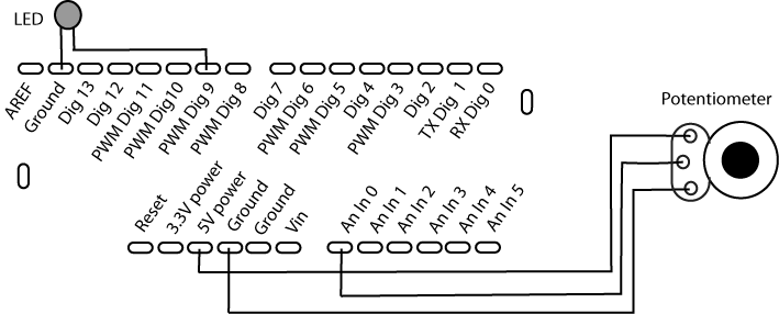
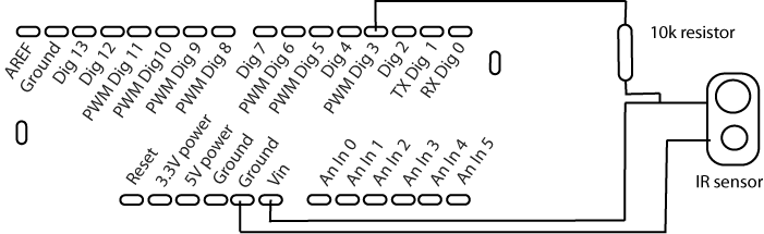
Potentiometers, perhaps known to you as knobs or a dials, work by receiving a current and increasing or decreasing the amount of voltage on a pin as it’s turned. For the Arduino controller, this means that the potentiometer is connected to three places on the board (Figure 8-1) to provide the three things that the potentiometer needs to communicate with the board:
Voltage (in this case, 5 volts from the +5-volt pin),
A ground (from the ground bus),
An analog input to read how much voltage is being returned (in this case, the An In 0 pin)
You can configure the Arduino board to read data from the
analog pins by using the analogRead() method. This method, like the
digitalRead() method, takes the
number of the port that should be read and returns the value that is
read from the port. In the case of analog data, that value can be
from 0 to 1,023.
In the following code snippet, the analog value sets the blinking rate of an LED:
int potentiometerPin = 0;
int ledPin = 13;
int val = 0;

void setup(){
    pinMode(ledPin, OUTPUT);
    Serial.begin(9600);
}

void loop(){
    val = analogRead(potentiometerPin);
    Serial.println(val);
    digitalWrite(ledPin, HIGH);
    delay(val);
    digitalWrite(ledPin, LOW);
    delay(val);
}
To use the value from the potentiometer to set the brightness of the LED, you need to remember that analog output can be any value from 0 to 255, so you divide the analog input value by 4, converting the 0 to 1,023 range to the 0 to 255 range:
int potentiometerPin = 0;
int ledPin = 9;
int val = 0;
void setup(){
// setup isn't doing anything, but we still need it here
}
void loop(){
val = analogRead(potentiometerPin);
Serial.println(val);
analogWrite(ledPin, val/4);
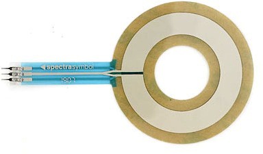
}A slightly different twist on the potentiometer is the 0.5-millimeter-tall soft potentiometer that provides a very different form factor that you can use for flatter, fingertip-tactile interfaces.
The soft potentiometer shown in Figure 8-2 is manufactured by Spectra Symbol and is widely available. A few other suppliers are creating them, so checking at any of the recommended suppliers should give you an idea of what’s available for your region and price range. This particular soft potentiometer can be wired the same as a standard dial potentiometer, while providing a much different appearance and experience for a user.
Using Lights
A light is generally used as a feedback mechanism to tell users that something is on or has changed, to inform them of progress by blinking, or to warn them. When a light blinks, you instinctively pay attention to it. When a light suddenly comes on, you notice it. When a light goes off, you tend not to notice. If a light is always on, you’ll notice only if you’re searching for the cause of something gone wrong.
Lights are one of the oldest electronic feedback mechanisms because they’re simple to engineer, easy to comprehend with a well-placed label or icon, and cheap.
Wiring an LED
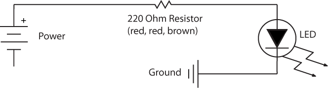
Attaching a small light to the Arduino board is quite easy. Create a circuit with a 220 Ohm resistor to the 5-volt pin of the Arduino and then connect that to the longer leg of the LED. Connect the shorter leg of the LED to the ground pin of the Arduino.
Figure 8-3 shows the electrical diagram.
This raises an interesting question: how do you wire multiple lights? Since the light simply requires a complete circuit and enough voltage to power the bulb, you can easily add multiple lights to the circuit and power them all at the same time, as shown in Figure 8-4.
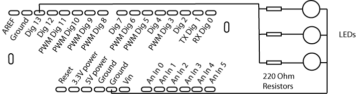
When the lights are wired to the digital out, both are turned
on or off by the digital port either sending a HIGH value or sending a LOW value. You can also send analog values
to the lights by using the analogWrite() and using any one of the
pins marked PWM to power the lights, but you’ll need to add a
resistor to the circuit:
int ledPin = 9;
int amountOfLight = 0;

void setup(){
}

void loop(){
    if(amountOfLight > 254) {
        amountOfLight = 0;
    }
    analogWrite(ledPin, amountOfLight);
    amountOfLight+=1;
    delay(10);
}
Since the loop() method is
going to repeat every 10 milliseconds, you can use that loop to
slowly increase the amount of power that is sent to the lights,
creating a slow linearly increasing glow. Of course, the next thing
you might want to do is add multiple lights and control them
independently. While this is fairly easy to do with a limited number
of lights by using the same number of lights as digital out or
analog out ports that the Arduino controller possesses, using more
lights in more complex configurations is an entirely different
matter. Chapter 11 will cover more complex
ways of using LEDs in your applications.
Detecting Touch and Vibration
A piezoelectric sensor (piezo sensor for short) is a device that uses the piezoelectric effect to measure pressure, acceleration, strain, or force by converting these factors to an electrical signal. Piezo sensors use a phenomenon called piezoelectricity, the ability of some materials (notably crystals and certain ceramics) to generate an electric potential in response to physical stress. What this means is that the material of a piezo sensor, usually a crystalline coating over metal, returns more current when bent or otherwise disturbed. This lets you detect very slight changes in the sensor, for example, a breeze or the touch of a finger.
The principles behind the piezo sensor should give you an idea of how the sensor connects to the Arduino board. A certain amount of current is sent through the sensor, and that current is fed through the sensor. When the sensor is bent, the resistance of the sensor increases, and the amount of current returned from the sensor is reduced. Many electrical supply stores carry small hobbyist piezo sensors (Figure 8-5) that have two wires attached to them.
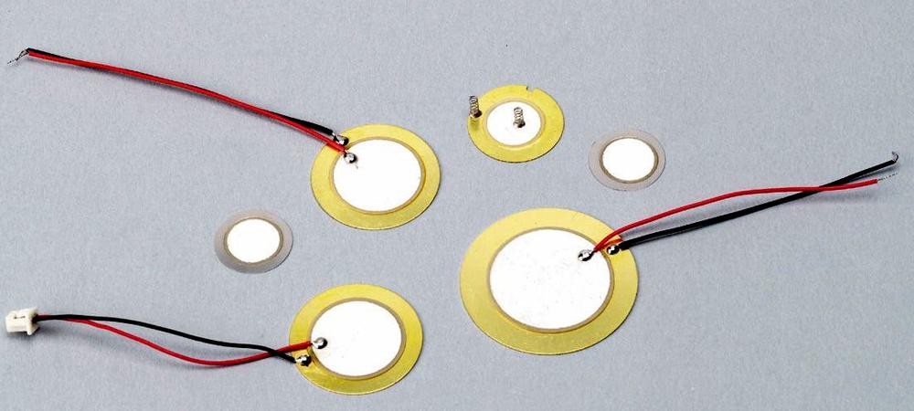
To connect the piezo sensor, you’ll want to connect 5 volts to the input of the sensor, the red wire, and connect the output of the sensor, the black wire, to an Analog In pin on the Arduino controller.
Reading a Piezo Sensor
The following code will detect vibration in a piezo sensor attached to your Arduino with 5 volts of power (+5V pin) connected to the red wire of the piezo and the other end of the piezo sensor connected to Analog In pin 2:
int piezoPin = 2; // input for the piezo
int ledPin = 13; // output pin for the LED
int val = 0; // variable to store the value coming from the sensor
void setup() {
pinMode(ledPin, OUTPUT); // declare the ledPin as an OUTPUT
}
void loop() {
val = analogRead(piezoPin); // read the value from the sensor
// a nice even number that could represent a little bit of change
if(val < 100) {
// if there's resistance on the piezo, turn the light on
digitalWrite(ledPin, HIGH);
} else {
// otherwise, turn the light off
digitalWrite(ledPin, LOW);
}
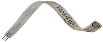
}Detecting force in a piezo sensor can also detect the amount of force up to a certain range; however, the piezo sensor reaches a maximum value quickly. If you want to detect more force than the piezo sensor allows, you can use a flexible pressure sensor. These sensors read the amount of force that is exerted on a flexible piece of electroconductive material and commonly range from 1 to 100 pounds of maximum force detection. The sensor in Figure 8-6, manufactured by FlexiForce, is accurate from 0 to 25 pounds of pressure and is about 0.2 millimeters thick, making it unobtrusive and easy to conceal inside levers, soft objects, punching bags, and shoes, among other possibilities.
Getting Piezo Sensors
RadioShack stocks a small piezo sensor kit that consists of a piezo sensor held inside a small plastic case. Carefully open the case to remove the sensor, or simply leave it inside the case. It’s easier to work with the sensor outside of the case, but it’s also more delicate, so be careful not to disconnect the wires from the back or to tear the material of the piezo element itself. You can also buy piezo sensors from a well-stocked electronics supplier.
Communicating with Other Applications
So far, we’ve covered getting input, which is one half of the
interaction or conversation; however, at some point, you’ll probably
want to use the input from the Arduino to communicate with other
applications built in Processing and openFrameworks. Communicating
with Processing and openFrameworks is done via the serial port. In
Chapter 4, we looked at using the Serial class in an Arduino application to
send debugging information to the Arduino IDE. So, thinking about that
for a moment, you’re sending a message from the Arduino controller to
the computer and listening to that message. That’s not some magic in
the Arduino IDE; it’s something that all modern computers are able to
do. Therefore, you can use the same Serial methods to communicate with a
Processing or openFrameworks application.
So, what is the Serial object
and what is serial communication? It’s a way of sending information
from your computer to another machine that could be another computer
but is more frequently another kind of device. Serial communication
uses a protocol called RS-232. This protocol dictates how messages are
sent and received using the serial port. Many devices use serial
communication to communicate with a parent computer: Bluetooth-enabled
devices, GPS sensors, older printers and mice, bar-code scanners, and,
of course, the Arduino board. How do you do it? Well, it’s pretty
low-level and can be pretty simple or quite complex. To send a message
from a Processing application to the Arduino board, the event flow is
like the following:
import processing.serial.*;

// Declare the serial port that we're going to use
Serial arduinoPort;

void setup() {
    // uncomment the next line if you want to
    // see all the available controllers
    // println(Serial.list());
Now you set up the communication between the Arduino and the Processing application. The following line may need to be changed if the Arduino isn’t connected on the first serial port of your computer:
    arduinoPort = new Serial(this, Serial.list()[0], 9600);
}

void draw() {}

void keyPressed() {
    // Send the key that was pressed
    arduinoPort.write(key);
}
When you send the key, it will be the ASCII representation of the key, which means that on the Arduino side, you need to listen for a number, not a character. This is important.
The constructor of the Serial
object has a few different signatures:
Serial(parent, name, rate)
Serial(parent)
Serial(parent, rate)
Serial(parent, name)
parent:PAppletIs the Processing application that owns the
Serialobject. You usually just usethis.rate:intIs the serial rate at which you’re communicating; 9600 is the default, so if you’ve set your Arduino controller to communicate at a different rate, you’ll want to change this.
name:StringIs the name of the port. If you uncomment the
Serial.list()call in the previous code snippet, you’ll see the names of all the available ports.
You can create the serial port in some other ways, but we’ll leave those for you to explore, because at the moment, we need to move on to the Arduino code.
The new stuff here is all in the loop() method of the Arduino
application:
int message = 0;    // for incoming serial data
int ledPin = 13;

void setup(){
    pinMode(ledPin, OUTPUT);
    Serial.begin(9600);    // opens serial port, sets data rate to 9600 bps
}

void loop() {
The Serial objects available() method tells how much data has
arrived and is available on the serial port from the Processing
application. This is important because were you to not wait until you
were sure that all the messages had been received, you might get
incorrect data. It’s important to always make sure that there is
something in the buffer before you try to use it. In the following
example, you’ll turn the light on if you get a ! from the Processing application, and
you’ll turn the light off if you get a ?. Otherwise, just ignore it:
    // do something only when we receive data:
    if (Serial.available() > 0) {
        // read the incoming byte:
        message = Serial.read();
         if(message == '!') {
            digitalWrite(ledPin, HIGH);
         }

         if(message == '?') {
             digitalWrite(ledPin, LOW);
          }
    }
}
In openFrameworks, you send messages to an Arduino controller by
using the ofSerial object. It’s quite similar
to the Serial object that
Processing contains, so the methods that it defines should be familiar
to you:
bool setup(string
            portName,
int baudrate)Starts up the communication between the openFrameworks application and the Arduino board using the name of the port, something like
"/dev/tty.usbserial-A6004920"if you’re on OS X or"COM1"if you’re on Windows.bool setup(int deviceNumber,int baudrate)Starts up the communication between the openFrameworks application and the Arduino board using the device number. This can be problematic if you have anything else plugged into your computer and don’t know the device number of the Arduino port.
int readBytes(unsigned char *
            buffer,
int length)Reads multiple bytes from the Arduino into a character array.
int writeBytes(unsigned char *
            buffer,
int length)Writes multiple bytes out to the Arduino.
bool writeByte(unsigned char
            singleByte)
Writes a single byte out to the controller.
int readByte()Reads a single byte from the controller. This is an int, so if the controller sends a character, you’ll get its ASCII representation.
In the previous Processing application, you simply sent the ASCII key number over the serial port to the Arduino board. To duplicate the same functionality in openFrameworks, you’d simply do what’s shown in Example 8-1.
#ifndef _OF_SEND_SERIAL
#define _OF_SEND_SERIAL

#include "ofMain.h"

class OFSendSerial : public ofBaseApp{

    public:
        void setup();
        void keyPressed(int key);
        ofSerial serial; // here's our ofSerial object that we'll use
};
#endif
You would implement it as shown in Example 8-2.
Sending Messages from the Arduino
To have a Processing or openFrameworks application receive
messages from Arduino, you need to make sure that something is
listening in the application. In Example 8-3, you
send a message to the serial port if digital pin 13 is HIGH, which could be any digital signal, a
button press, or something similar.
int buttonPin = 13;

void setup() {
    // open the serial port at 9600 bps:
    Serial.begin(9600);
}

void loop() {
    if(digitalRead(buttonPin ) == HIGH) {
        Serial.print("!");
    } else {
        Serial.print("?");
    }
    delay(200);
}
In the following Processing code (Example 8-4), you listen on the port for any incoming information from the serial port and print the data that you receive from the Arduino controller. Of course, you can do far more sophisticated things with the data you receive, but for this demonstration, let’s keep it simple.
import processing.serial.*;

Serial arduinoPort;
void setup() {
    // set up the communication between the Arduino and the Processing app
    arduinoPort = new Serial(this, Serial.list()[0], 9600);
}

void draw() {
    // Expand array size to the number of bytes you expect
    byte[] inBuffer = new byte[7];
    while (arduinoPort.available() > 0) {
        inBuffer = arduinoPort.readBytes();
        arduinoPort.readBytes(inBuffer);
        if (inBuffer != null) {
            String myString = new String(inBuffer);
            println(myString);
        }
    }
}
openFrameworks
Communication between an Arduino board and an openFrameworks
application uses the ofSerial
object. The ofSerial class
defines the following methods:
void
              enumerateDevices()
Prints out to the console all the devices that are connected to the serial port.
void close()Stops the openFrameworks application from listening on the serial port.
bool setup()Is the setup method without the port name and rate, by default it uses port 0 at 9600 baud.
bool setup(string
              portName,
int baudrate)Uses the
portNameto set up the connection.bool setup(int deviceNumber,int baudrate)Uses the
devicenumberif there are multiple devices connected.int readBytes(unsigned char * buffer,int length)Reads any bytes from the buffer that the Arduino controller has sent.
int writeBytes(unsigned char *
              buffer,
int length)Writes some data to the serial buffer that the Arduino controller can receive.
bool writeByte(unsigned char
              singleByte)
Writes a single byte to the serial buffer for the Arduino controller.
int readByte()Reads a single byte from the buffer; it returns −1 on no read or error.
void flush(bool
              flushIn,
bool flushOut)Flushes the buffer of incoming serial data; you can specify whether both the incoming and outgoing data are flushed. If there’s some data in the serial buffer, it will be deleted by calling
flush().int available()Returns 0 if the serial connection isn’t available and another number, usually a 1, if it is.
We show a common pattern for working with the ofSerial application here. First, define
the number of bytes that you’re expecting. A Boolean value, like a
button being pressed, would just be a single byte. The values from a
potentiometer would be integers and so would be 2 bytes. This is the
header file for the application:
#define NUM_BYTES
Next, define the application:
class SerialDemo : public ofBaseApp {
    public:
        void setup();
        void update();
Next, use a Boolean value to determine whether you should try
to read from the buffer. An openFrameworks application runs faster
than the serial protocol can send and receive information, so you
should try to read from the serial buffer only every five frames or
so. This value will be set to true when you’re ready to read from the
serial port; otherwise, it remains false:
        bool bSendSerialMessage;    // a flag for sending serial
        // this will be used to count the number of frames
        // that have passed since the last time the app reads from the serial port
        int countCycles;
Here’s the ofSerial
object:
        ofSerial serial;
};
#endif
In the .cpp file for your
application, the setup() method
of your application will need to call the setup() method of the ofSerial object:
void testApp::setup(){
    bSendSerialMessage = false;
    serial.enumerateDevices(); // this will print all the devices
    // this is set to the port where your device is connected
    serial.setup("/dev/tty.usbserial-A4001JEC", 9600);
}
The update() method of
ofApplication should do all the
reading from and writing to the serial port. When the bSendSerialMessage flag is set to true, the openFrameworks application sends
a message to the Arduino board telling it that it’s ready to receive
data:
void testApp::update(){
    if (bSendSerialMessage){

        // send a handshake to the Arduino serial
        sIf the erial.writeByte('x'),
        // make sure there's something to write all the data to
        unsigned char bytesReturned[NUM_BYTES];
        memset(bytesReturned, 0, NUM_BYTES);
The openFrameworks application reads bytes from the serial port until nothing is left to read:
        // keep reading bytes, until there's none left to read
        while( serial.readBytes(bytesReturned, NUM_BYTES) > 0){}
     }
Once you’ve read all the data out of the serial port and into
the bytesReturned variable, set
the bSendSerialMessage flag to
false:
     // wait a few cycles before asking again
     bSendSerialMessage = false;
    }
Now you can use the signal sent from the Arduino however you’d
like. The countCycles variable is incremented
until it hits 5; then the bSendSerialMessage variable is set to
true, and the next time the
update() method is called, the
openFrameworks application
will read from the serial port:
    countCycles++;
    if(countCycles == 5) {
        bSendSerialMessage = true;
        countCycles = 0;
    }
}
Detecting Motion
Motion detection is one of the most immediately satisfying experiences to create for a user or viewer, and it’s also quite simple to implement. You can use motion detection in an environmental way, with the motion detection not being apparent to the user, or you can use it more like a control to signal the computer. The difference between being apparent or hidden for the user is determined by the placement and obviousness of the control. A motion detector for security should not be apparent to the user, or it will not be as effective in securing the area around it. A motion detector to detect whether a person is putting their hands under a faucet to start the flow of water, while not readily visible, is a control that the user is aware of, for example.
PIR Motion Sensor
You provide motion detection for your application in several ways. One is a passive infrared (PIR) motion sensor, shown in Figure 8-7.
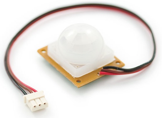
If your PIR sensor comes with a connector like the one shown in Figure 8-7, you may need to cut this off so you can connect the sensor to the Arduino controller, as shown in Figure 8-8.
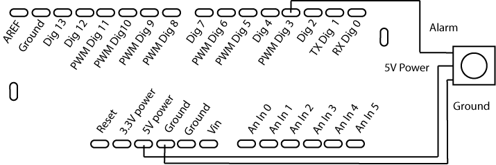
The following code will light the LED on the Arduino controller when motion is detected by the PIR sensor. The source code is quite simple:
int alarmPin = 3;    // motion alarm output from PIR
int ledPin = 13;     // output pin for the LED
int motionAlarm = 0;

void setup(){
    pinMode(ledPin, OUTPUT);
    digitalWrite(ledPin, LOW);
}

void loop(){
    motionAlarm = digitalRead(alarmPin);
    // this is a very simple loop that lights an LED if motion detected
    if(motionAlarm == HIGH){
        digitalWrite(ledPin, HIGH);// we've detected motion
        delay(500);
        digitalWrite(ledPin, LOW); // turn off the light
    }
}
The kind of motion detection offered by the PIR motion detection sensor is really useful only for very simple interactions. Combined with another system, though, it can be quite powerful. Applications or machines that turn on or enter a ready state when a user approaches create a powerful affordance: preparedness. Other, more precise ways exist for not only detecting motion but also gathering more information about the motion and position of an object; you’ll learn about these methods in the next section.
Reading Distance
Some sensors provide information about the distance to an object, and these are extremely useful because they detect presence and distance. While a simpler motion sensor can tell you whether something has moved within its range, a distance sensor will also tell you how far away that thing is. They’re used extensively in hobbyist robots because they’re simple to program, do not require a great deal of power, and provide very important information, such as how far away objects are. With that sort of information, you can go further than simply giving a user or audience binary feedback (such as you’re moving or you’re not) and give them analog feedback (such as you’re this far away, now this far, now this far). It creates a more fluid interaction and experience because, while it may start rather suddenly when a person comes into range of the sensor, it does not end there.
You’ll see two technologies widely used: ultrasonic and infrared. Ultrasonic sensors work by detecting how long it takes a sound wave to bounce off an object. The sensor provides an output that indicates the amount of time it takes for the echo signal to return to the sensor, and the magnitude of the echo delay is proportional to distance. One of the most popular lines of ultrasonic sensors is the Daventech Range Finder series, which has several different models varying in price and the range at which they function. The two most common are the SRF04 and SRF08. The SRF04 is a good and cheap sensor that is accurate to about 4 meters. The SRF08 is a little more expensive and has a range of about 8 meters.
Daventech sensors provide an output signal that has a pulse
width proportional to distance. Using the Arduino pulseIn() method, this signal can be
measured and used as a distance value:
long echo = 0;
int usPin = 9; // Ultrasound signal pin
long val = 0;
void setup() {
    Serial.begin(9600);
}

long ping(){
    pinMode(usPin, OUTPUT); // Switch signalpin to output
    digitalWrite(usPin, LOW); // Send low pulse
    delayMicroseconds(2); // Wait for 2 microseconds
    digitalWrite(usPin, HIGH); // Send high pulse
    delayMicroseconds(5); // Wait for 5 microseconds
    digitalWrite(usPin, LOW); // Holdoff
    pinMode(usPin, INPUT); // Switch signalpin to input
    digitalWrite(usPin, HIGH); // Turn on pullup resistor
    echo = pulseIn(usPin, HIGH); // Listen for echo
Now the value returned from the pulseIn() method can be used to determine
how far away the object is in centimeters from the ultrasonic sensor
by multiplying the echo by 58.138. This value comes from the
manufacturer’s specifications sheet, so you might want to check your
sensor before assuming that this code will work. If you want the value
in inches, you can multiply the value by 0.39:
    long ultrasoundValue = (echo / 58.138);
    return ultrasoundValue;
}

void loop() {
    long x = ping();
    Serial.println(x);
    delay(250); //delay 1/4 seconds.
}
Try adding a video or audio application written in Processing or openFrameworks that uses an ultrasonic sensor to control the speed of a video or audio file playing. Another common use of distance sensing is to detect presence or the absence of presence: starting an application or device when motion is detected within a certain range or when something that the device is programmed to expect is absent. An alarm on a door or window could function this way, as could a simple trip wire type of interaction. Motion detection is also an interesting possibility for mobile or handheld devices if you indicate to the user how to direct the sensor. This allows them to point the device at an object or surface to activate a reaction to it based on distance. Used in tandem with an accelerometer within the same handheld device or as part of a large set of controls, buttons, or potentiometers, a distance sensor can be a rich input for an interface to utilize.
Another way to measure distance, which uses technology borrowed from autofocus cameras, is infrared. The infrared sensor has two lenses, the first of which emits a beam of infrared light and the second of which detects any infrared light reflected back. If the second lens detects any light, then the angle of the beam is measured by an optical sensor and used to determine the distance. The greater the angle, the greater the distance. The Sharp Ranger line is a popular choice, particularly for measuring accurate distances up to a meter.
Figure 8-9 shows how to wire an infrared sensor to your Arduino board.
Reading Input from an Infrared Sensor
To read data from an IR sensor, you need to initialize the pin
that will be connected to the IR sensor and use the analogRead() method to read values from
the sensor.
Generally, the sensor will report slight differences in readings from the sensor. You can smooth out your reading using the average of several readings. This may not be necessary, but if you find that your readings are slightly erratic, then using an average may be the answer. The following snippet is an example of averaging the readings from 10 IR sensor readings:
#define NUMREADINGS 10

int readings[NUMREADINGS];                // the readings from the analog input
int index = 0;                            // the index of the current reading
int total = 0;                            // the running total
int average = 0;                          // the average

int inputPin = 0;

void setup()
{
    Serial.begin(9600); // start serial communication
    for (int i = 0; i < NUMREADINGS; i++)
        readings[i] = 0; // initialize all the readings to 0
}

void loop()
{
    total -= readings[index]; // subtract the last reading
    readings[index] = analogRead(inputPin); // read from the sensor
   total += readings[index]; // add the reading to the total
    index++;

    if (index >= NUMREADINGS) {// if at the end of the array
        index = 0; // start again at the beginning
    }
    average = total / NUMREADINGS;// calculate the average
    Serial.println(average); // send it to over the Serial
}
Understanding Binary Numbers
As you may have heard at some point, computers and electronic components do not generally use decimal numbers. That means values like 17, 4, and 1,977—while certainly recognizable and usable in any computer program—aren’t recognizable by the computer at runtime in that decimal form. Instead, computers and some sensors use binary counting. What follows is a quick introduction to binary numbers and, more importantly, how binary numbers and bit shifting work.
Binary Numbers
When you count from 1 to 13, you’ll notice that you’re counting up to 9 and then shifting a 1 over; then, you’re continuing counting until you get to the next 9:
| 9, 10, 11....19, 20, 21....29, 30, 31...99, 100, 101...999, 1,000, 1,001 |
Notice how every time a 9 appears in the last place, you increment the value on the left and put a 0 on the right, and if all the numbers are nine, you add a 1 to the front. This counting system is called decimal. It’s something so automatic that it takes a moment to realize that this is just one counting system among many. A binary counting system is similar to a decimal counting system, but instead of using 10 numbers to count, it uses only 2, which is why it’s called binary.
When you count in binary numbers, the numbers reset every two values, so to count to four, you do the following:
| 1, 10, 11, 100 |
Notice how every time you have a 1 in the right column, you add another 1 on the left and transform the number on the right to a 0. Replicating the counting that you did in decimal system would look like this:
| 1001, 1010, 1011...10011, 10100, 10101...11101, 11110, 11111...1100011, 1100100, 1100101, 1100110...1111100111, 1111101000, 1111101001 |
That requires more numbers for certain, but why? Remember that underneath all the niceties that a computer provides to make it easier for us to work with code and numbers, the computer represents everything by the presence or absence of an electrical current. For representing values simply by a presence or an absence, what could be better than a numbering system with two values: 0 and 1?
Bits and Bit Operations
Now that you have a rough idea of how counting in binary works, let’s look at using objects that are represented in binary using bit shifting.
Bit shifting means shifting bits around by places. Although the uses of it are a little tricky to understand, the principles behind it aren’t. Consider a situation where people are discussing salaries. Since they all make salaries that are measured in the thousands, they might say things like “52K” or “65.” What they’re doing, really, is shifting the numbers by three places so that 48,000 becomes 48. Now, some information isn’t explicitly expressed, but if you know you’re talking in thousands, then no information is actually lost. If you know that when you say “70” you really mean 70,000, it isn’t a big deal, because you can always mentally “shift” those three places. The same works with percentages. Everyone knows that the “50” in a 50/50 chance is really 0.5. You just shift the value up two places to make it easier to think about because percentages use nice round numbers and those are easier to think and talk about. Bit shifting is essentially the same principle, except that shifting in binary is a bit more natural for a computer than for a human so it looks a bit strange at first. Bit shifting looks like this:
Let’s say you have the integer 3:
int val = 3;
You know that as an int this variable has 16 bits available to it, so that, as far as your computer is concerned, you’re really storing this:
| 0000 0000 0000 0011 |
and all those extra zeros are just placeholders. The only things doing anything are the last two numbers. Normally, this isn’t a big deal at all, because computers have enough memory that wasting a few extra spaces is nothing to get bent out of shape about. That’s fine for a laptop or an Arduino controller, but sometimes for very small sensors that’s not fine, and they might do something like send you an integer in two pieces. And that could be a problem. Why? Well, what if you had a relatively big integer, for example, 30,000?
| 0111 0101 0011 0000 |
If you had to send that integer as two pieces in binary the first time, you’d get the following:
| 0111 0101 |
This is 117 in decimal, and the second time you’d get the following:
| 0011 0000 |
and this is 48 in decimal. Now, even if you know that you’re supposed to be getting something kind of like 30,000, how are you going to turn those two numbers into what you’re expecting back? The answer lies in the magic of shifting. Let’s say that you’re getting a value from an accelerometer sensor that sends information in two pieces. Since you know that the sensor is sending the first 8 bits of the number and then the second 8 bits (that is, the two halves of the integer), just shift the first 8 bits over and then put the next 8 bits behind it. To do this, use a bit shift operator:
In the code snippet above, the variable val is now 6, because 3 in binary is 11,
so moved over 1, it’s 110, or 6.
Back to the sensor example, say that the total is 30,000, or 0111 0101 0011 0000 in binary. To shift the integer values over correctly so you get the first half of the number, you’d do the following:
int valueFromSensor = firstHalfOfValue; //this is 0111 0101
valueFromSensor <<= 8; //now our value is shifted over correctly
// since the second half won't affect the top, just add it
valueFromSensor += secondHalfOfValue;
Another bit shift operation is the right shift, which works the opposite of the left shift. It’s not used as commonly in the types of code that you’ll encounter because there isn’t as much of a need to make big numbers into small ones, but it’s available, and it’s good to know:
>>Shifts the value on the left down by the number of places indicated on the right.
>>=Shifts the value on the left down by the number of bits indicated on the right, just like
+=adds the value on the right to the value on the left:int val = 100;// val is 1100100 val >>= 2; // removing the last two digits, val is now 11001 or 25
So, to recap in a slightly more academic fashion, you have this:
00010111 << 1 =  00101110
00010111 >> 1 =  00001011
In the first case, the left digit is shifted out, and a new 0 was shifted into the right position. In the second case, the last digit, a 1, was shifted out, and a new 0 was placed into the left position. Multiple shifts are sometimes shortened to a single shift by some number of digits. For example:
00010111 << 2 = 01011100
A word of warning and a word of explanation as well: for the Arduino controller, an integer is 16 bits, that is, a binary number with 16 places. It’s very important to note that the first of those digits indicates whether the number is negative or positive, so the number is only 15 digits long, with a final bit to indicate either a positive or negative number. Here’s a few integer values:
0111111111111111 = 32767
Now, you would think that the value of that number if it was shifted to the left would be 65,534, but it’s not, because the first bit says whether the number is negative or positive. It would actually be the following:
1111111111111110 = −2
Why is that important? When you start bit shifting numbers around, you may encounter some surprise negative numbers. This would be one source of those sorts of errors.
Why Do You Need to Know Any of This?
The complete answer lies at the end of the section Introducing I2C, where you begin working with I2C. Beyond that, though, this section was an excellent introduction to how the fundamentals of a computer actually function. It’s also good to understand how bits and bit shifting actually works, because when working with sensors and the Arduino controller, you’ll frequently see the bit shifting operators used in example code. As mentioned earlier, frequently smaller electrical components do not use larger numerical values and so will assume that any controller accessing their data can assemble those larger values using bit shifting. Now that you’ve read this section, you’ll be able to follow along with how those controls send data.
Detecting Forces and Tilt
Accelerometers are sensors that detect forces acting upon them, specifically, the force of acceleration. Much the same way as you can detect the acceleration of your car when you press on the gas by the feeling that you have of being pushed back into the seat, the accelerometer detects the force of any acceleration onto it by detecting the shift in the forces acting on the internals of the sensor and reporting how much they’ve changed. Two-dimensional accelerometers detect forces registering changes in the x- and y-axes, and three-dimensional accelerometers detect changes in the x-, y-, and z-axes.
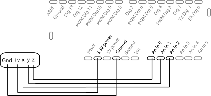
In this example, you’re going to use an SEN-00849, which is a simple board that holds the accelerometer and provides easy access to its x, y, and z pins. Later in this chapter, we’ll look at another accelerometer, but for now, the SEN-00849 is easy to use; match the pin to an Analog In, and you’re off to the races.
Figure 8-10 shows the wiring diagram to connect to an accelerometer.
The following snippet is a simple example of reading from an
accelerometer using the analogRead() method to read the value for
the plane that the accelerometer reports values for:
int xpin = 2;         // x-axis of the accelerometer
int ypin = 1;         // y-axis
int zpin = 0;         // z-axis (only on 3-axis models)

void setup()
{
    Serial.begin(9600);
}

void loop()
{
    Serial.print(analogRead(xpin));
    Serial.print(" ");
    Serial.print(analogRead(ypin));
    Serial.print(" ");
    Serial.println(analogRead(zpin));
    delay(50);
}
Although this is a simple application, it’s an effective one. Once you get the values from the accelerometer, you can do all kinds of things with them, such as create a drawing tool, create a pointer, control a sound, change a game, or rotate in a 3D world.
In the following example, you’re going to send a message from an accelerometer to an openFrameworks application. First up is the code for the Arduino application. You’ll see a few familiar things here, including the averaging of data from the controller, just like in when you saw a sketch with the infrared sensor. As you’ll notice after working with an accelerometer for any length of time, the data from the accelerometer is jumpy, varying quite quickly by as much as 100 with no input. To avoid this, you’ll simply average that value over eight readings:
int groundpin = 18;             // analog input pin 4
int powerpin = 19;              // analog input pin 5
int xpin = 5;                   // x-axis of the accelerometer
int ypin = 3;                   // y-axis
int zpin = 1;                   // z-axis (only on 3-axis models)

int xVal = 0;
int yVal = 0;
int zVal = 0;

int xVals[8];// an array of the last 8 x coordinate readings
int yVals[8];// an array of the last 8 y coordinate readings
int zVals[8];// an array of the last 8 z coordinate readings
int xAvg = 0; // the x value we'll send to our oF application
int yAvg = 0;// the y value we'll send to our oF application
int zAvg = 0;// the z value we'll send to our oF application

int currentSample = 0;

void setup()
{
  Serial.begin(19200);
}

void loop()
{
    // we use currentSample as an index into the array and increment at the
    // end of the main loop(), so see if we need to reset it at the
    // very start of the loop
    if (currentSample == 8) {
       currentSample = 0;
    }

    xVal = analogRead(xpin);
    yVal = analogRead(ypin);
    zVal = analogRead(zpin);

    xVals[currentSample] = xVal;
    yVals[currentSample] = yVal;
    zVals[currentSample] = zVal;
Here is where the values are averaged to avoid having strong spikes or dips in the readings:
    for (int i=0; i < 8; i++) {
        xAvg += xVals[i];
        yAvg += yVals[i];
        zAvg += zVals[i];
    }
These will under read for the first seven cycles, but that shouldn’t make a huge difference unless you need to read the value from the accelerometer right away, in which case you could just not send the data for the first seven cycles:
        xAvg = (xAvg / 8);
        yAvg = (yAvg / 8);
        zAvg = (zAvg / 8);
    // ---------------------
    // print the value only if we get the 'handshake'
    // ---------------------
    if( Serial.available() > 0) {
         Serial.read();
        printVal(xAvg);
        printVal(yAvg);
        printVal(zAvg);
    }
    currentSample++; // increment the sample

}

//here's the tricky stuff: break the number into two
// bytes so we can send it to oF without any problems
void printVal(int val) {
     byte highByte = ((val >> 8) & 0xFF);
     byte lowByte = ((val >> 0) & 0xFF);

     Serial.print(  highByte, BYTE );
     Serial.print(  lowByte, BYTE );

}
You’ll notice that the value prints to the serial only if you’ve
gotten something back from the openFrameworks application. Why is
this? An Arduino controller and a C++ application run at slightly
different speeds. If you were to send a message to the C++ application every time the
controller ran its loop() method,
you’d send a message while the application was still in the middle of
processing the previous message. It’s as if you were trying to write
down what someone was saying as they were talking: it’s quite helpful
if they stop at the end of a sentence and wait for you to catch up.
This is the same thing as when the openFrameworks application has
finished processing a message from the Arduino board and sends a
message back, in this case a single character, x,
just to say: “OK, I’m ready for the next message.” This ensures that
the openFrameworks application hears the right values, and the Arduino
board sends information only when the openFrameworks application is
ready.
Let’s look at the openFrameworks code in Example 8-5. It’s short, and it’s not very exciting, but it does show you something important: how to get complex data from the Arduino board into your openFrameworks application. What to do with that information once you get it is entirely up to you. You could use it to draw, you could use it to create a sound like an electronic theremin, or you could use it control the speed and distortion of a video; it’s entirely up to you.
#ifndef _OF_ARDUINO_COMM
#define _OF_ARDUINO_COMM

#include "ofMain.h"

#define NUM_BYTES 6

class OFArduino : public ofBaseApp{

    public:

        void setup();
        void update();
        void draw();

        int xVal;
        int yVal;
        int zVal;

        bool    bSendSerialMessage;    // a flag for whether to
 send                                         // our 'handshake'
        //data from serial, we will be reading 6 bytes, two bytes for each integer
        unsigned char bytesRead[NUM_BYTES];
        int countCycles; // this is how to keep track of our time
        ofSerial serial; // this is ofSerial object that enables all this
};

#endif
Note the countCycles
variable. You’re going to use that to make sure that you’ve gotten all
information from the serial buffer before sending another handshake
message to the Arduino board. Simply count to 5, and then get the next
set of data. You’ll see this in the update() method, shown here in Example 8-6.
#include "OFArduino.h"


void OFArduino::setup(){

    countCycles = 0; // start our count at 0
    bSendSerialMessage = true; // send a message right away
    // serial.enumerateDevices(); // uncomment this line to see all your devices

    // set this to our COM port, the same one we use in the Arduino IDE
    // the second part is the baud rate of the controller
    serial.setup("/dev/tty.usbserial-A6004920", 19200);
}

void OFArduino::update(){

    if (bSendSerialMessage){
        // send a message to the Arduino controller telling it that we're
        // ready to get accelerometer data
        serial.writeByte('x'),

        unsigned char bytesReturned[NUM_BYTES];
        memset(bytesReturned, 0, NUM_BYTES);

        // keep reading bytes, until there's none left to read
        while( serial.readBytes(bytesReturned, NUM_BYTES) > 0){
        };

        // make our integers from the individual bytes
        xVal = bytesReturned[0];
        xVal <<= 8;
        xVal += bytesReturned[1];

        yVal = bytesReturned[2];
        yVal <<= 8;
        yVal += bytesReturned[3];

        zVal = bytesReturned[4];
        zVal <<= 8;
        zVal += bytesReturned[5];

        printf("first  %i %i %i
", xVal, yVal, zVal);
        // get ready to wait a few frames before asking again
        bSendSerialMessage = false;
    }

    countCycles++;

    if(countCycles == 5) {
        bSendSerialMessage = true;
        countCycles = 0;
    }
}
Accelerometers are very rich territory for interaction, particularly when dealing with mobile or handheld devices. Anything that a user can directly manipulate in a physical way becomes an excellent candidate for an accelerometer. Tilting, shaking, and positioning can all be used as input methods via an accelerometer. Coupled with an unwired transmission via the XBee wireless data controller, the accelerometer allows the user free motion around a space while still retaining their ability to send input.
Introducing I2C
With Inter-Integrated Circuit (I2C), you very quickly get into some complicated concepts. If you’re interested, come along for the ride; if not, return to this section when you need it. When might you need it? Well, you need it when you need to communicate with an LCD display, a complex temperature sensor, a compass, or a touch sensor.
First, you should understand the concept of a clock in device communication. A device needs to keep track of its timing, in other words, how frequently it should be sending high and low signals out to any other devices connected to it. If a device has an internal clock, like the Arduino controller, then it can keep its own time. That’s fine for the Arduino controller, because you expect that you’re going to be sending it instructions and then having it run on its own. But what about something that you don’t expect to run on its own? For example, what about a compass sensor? You expect that you’re going to plug it into something to help it display information and know when to turn on and off, probably even providing power for it. It’s a reasonable assumption that whatever the compass sensor is going to be plugged into will have a clock, so why can’t you just use that clock instead of needing to have one in the compass? The answer is, you can. The catch, though, is that in order to use the clock of the controller, you need to be connected to that clock and get messages on it. This is what I2C is for—allowing multiple devices to be connected to a larger device in a network of sorts that will tell it when to update and read data from it. This network looks something like Figure 8-11.
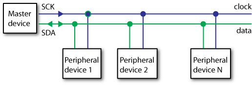
From the diagram in Figure 8-11, you’ll notice that multiple devices are connected to the master device. This is one of the great powers of I2C. It allows you to communicate with up to 127 different devices. They can’t all communicate at the same time, because there’s only one data line, but with a little clever code you can ensure that all the devices on the line know when they should be talking, or sending information, and when they should be listening, or reading the information on the data line. The clock ensures that synchronizing all these devices is fairly easy, because the master device simply tells all the slave devices when to talk and when to listen. The slave devices can be anything, even other Arduino controllers, which should give you not only a hint of how powerful I2C can be but also some bright ideas about distributing your application across multiple Arduino controllers.
I2C is built into the Arduino controller. Analog Pin 4 is the SDA, or data pin, and Analog Pin 5 is SCK, or clock pin. Plugging a device into the Arduino controller and creating an I2C circuit are both quite easy. I2C communication, however, is generally a little more difficult and would involve some rather intricate-looking code if not for the Wire library created by Nicholas Zambetti to work with I2C communication.
First, here’s an example of how to set up I2C using the Wire library in an Arduino sketch:
#include <Wire.h>

void setup(){
    Wire.begin(); // this 'joins' or initializes the circuit
}
That’s it. It’s not so bad, right? Next, here’s how to send a command to a slave device:
Wire.beginTransmission(20); // transmit to device #20
Wire.send("x is ");        // sends five bytes
Wire.send(x);              // sends value of x as one byte
Wire.endTransmission();    // stop transmitting
The beginTransmission()
method indicates the device to which you want to send data. Now, this
is very important to understand and admittedly counterintuitive. The
number of the device doesn’t actually have anything to do with the
physical location of the device—it’s the device identifier. We’ll talk
more about this later, but suffice to say that either the device will
generally be set by the manufacturer of the device or you will have to
set it manually. The send() method
indicates what you’re going to send to the device, and it’s very
important because devices have different commands in different formats
and send and receive information in formats tailored to their
function. This means that it’s important to read the manual or data
sheet for any device that you’re trying to communicate with. To finish
the transmission, you call the endTransmission() method.
So, that’s the first step of using I2C with Arduino. The next step is to request information from a device. You need to know how much data you’re expecting from the device that you’re communicating with. For example, if you’re expecting a single character, you need to know that and expect that from the device. Again, this is where the data sheet and documentation for any device will come in handy. You’ll know just what data any device will send in response to any particular request and what that data represents.
In the following snippet, you expect that the device with the
address of 2 will be sending 6 bytes of information, and you indicate
that with the requestFrom()
method:
Wire.requestFrom(2, 6);    // request 6 bytes from slave device #2
while(Wire.available()){    // slave may send less than requested
    char c = Wire.receive(); // receive a byte as character
    Serial.print(c);         // print the character
}
The requestFrom() method uses
the following format:
Wire.requestFrom(whichDevice, howManyBytes);
The requestFrom() method uses
two parameters:
whichDeviceIs the identification number of the device from which you’re requesting data.
howManyBytesIs the number of bytes that you’re expecting the device to send. This is yet another reason to consult the data sheet and a fine justification, if one was needed, for spending a little time studying the number of bytes that different data types require.
The Wire library also defines methods for having your Arduino controller act as a slave to another master control (another Arduino or another kind of device), but we’re not going to get into those at the moment. Instead, let’s look at how to use the Arduino controller for a slightly different kind of LED light than you first looked at, using the BlinkM controller.
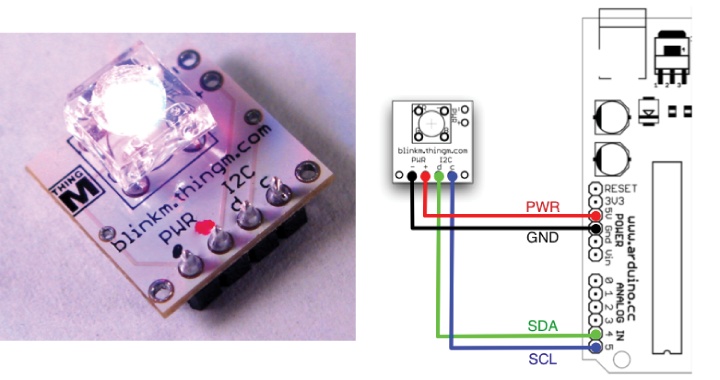
A great site and resource for information on electronics, hacking, and good ideas all around is Tod Kurt of ThingM. He and his partner have created a nifty little light called the BlinkM, shown in Figure 8-12, that lets you control the color of the light and set sequences of colors and blinking patterns.
The following code is quite simple and liberally borrows from
the BlinkM examples but does show a couple of really interesting
things about I2C. The first thing to notice is that you address the
BlinkM, which means that you give it an address that it will use for
I2C communication. This means that you could connect multiple BlinkM
controllers and send commands to each of them independently of the
other. The address is a single byte, and you use it for all the BlinkM
commands that you send. The Wire library is hidden within the BlinkM
functions that are imported in the #include statement at the top of the file,
which is nice, because it lets you concentrate on what’s possible with
the I2C library before delving too deeply into it. You can give a
controller an address and then use that address to control that
particular component. To start, the following code sends a
hexadecimal-based RGB color to the BlinkM via a serial
command:
#include "Wire.h"
#include "BlinkM_funcs.h"
The address can be any value that you set BlinkM to. If you
don’t know how to set the BlinkM address, then you can leave it at the
default value: 0x10.
byte blinkm_addr = 0x10; // the address to set the BlinkM to
char serInStr[6];  // array to hold the HEX color the user inputs

void setup()
{
Here is where you initialize the BlinkM. The BlinkM_stopScript() method stops the BlinkM
from running any script that has been uploaded to it
previously:
    BlinkM_beginWithPower(); // start up the blinkM
    BlinkM_setAddress( blinkm_addr );  // set the address
    BlinkM_stopScript(blinkm_addr); // stop the BlinkM from running its script
    Serial.begin(9600);

}

void loop()
{
    if(Serial.available() >=6) {
        for(int i=0; i < 6; i++) {
            serInStr[i] = Serial.read();
        }
    }
For each RGB value in the color that you want the BlinkM to
display, create a byte value that
contains that value. In this example, the hexadecimal numbers sent
over serial port from the Arduino console (or any other kind of
application, for that matter) are used to create those bytes. Once
you’ve created all the values, you can pass them to the BlinkM_fadeToRGB() method:
        byte a = toHex( serInStr[0],serInStr[1] );
        byte b = toHex( serInStr[2],serInStr[3] );
        byte c = toHex( serInStr[4],serInStr[5] );
        BlinkM_fadeToRGB( blinkm_addr, a,b,c);
    }
}
This method takes a hexadecimal number up to 255 and converts it into a byte value:
// copied directly from the BlinkM examples
#include <ctype.h>
uint8_t toHex(char hi, char lo)
{
    uint8_t b;
    hi = toupper(hi);
    if( isxdigit(hi) ) {
        if( hi > '9' ) hi -= 7;      // software offset for A-F
        hi -= 0x30;                  // subtract ASCII offset
        b = hi<<4;
        lo = toupper(lo);
        if( isxdigit(lo) ) {
            if( lo > '9' ) lo -= 7;  // software offset for A-F
            lo -= 0x30;              // subtract ASCII offset
            b = b + lo;
            return b;
        } // else error
    }  // else error
    return 0;
}
What would you add to have another BlinkM connected to your Arduino? If you answered “another address,” you would be correct. All that is required to wire them up is to attach the second BlinkM to Analog Out Pins 4 and 5 of the Arduino controller to connect it to the I2C circuit. The rest is up to you to complete as a project.
What Is a Physical Interface?
Not all interactive applications require a physical interface for a user to send input into a system, but many do. The more controls that you provide to your user, the more important the organization used to present those controls becomes. The more complex the interaction between your application and the user, the more control the user will need over the application. In these situations, an interface that provides some sense of what can be input and how the system regards that input helps a user understand what can be done with an application and how to do it. You can use the following to help when creating an interface:
- Appearance and labeling
Any control can be labeled by a piece of text, by its color, or by its appearance. This can be quite simple or quite complex, whimsical or purely functional. The labeling of a control can be revealed, animated, variable, or based on the state of an application. Consider all the different elements that can contribute to the labeling of a control: color, typography, material, size, weight, and texture. Any or all of these can be used in novel and interesting ways or in predictable ways that will reassure a user.
- Task-based organization
Controls that perform the same task should be organized by their appearance and by their location within the interface. The layout of many commonly used programs displays this characteristic; tool palettes, menus, mixing consoles, and computer keyboards all group their individual controls by the larger task.
- Alignment organization
Elements that are visually aligned with one another become related to one another when a user’s eye tracks across the interface. This is particularly important in the discovery period of an application, which is the period when a user is trying to figure out what the system does and can do by the interface. Alignment can indicate which objects are related to one another, which objects are subordinate to another.
The organization of controls does two things: it aids the user in understanding the system, and it provides a personality for the system. The system must provide some feedback of what it’s doing for the user to understand not only why the system has done what it already has done, but also what it’s going to do in the future. You can script some things for a user, but you can’t script all things. For anything that you can’t script, you should provide meaningful allowances and meaningful descriptors. Chapter 11 examines physical feedback in much greater detail.
What’s Next
Now that you have a grasp on how to use some basic and not so basic controls, you can begin to play with them and play with the interactions that people might have with them. Remember, even though you have to worry about all the technical details, your users and participants don’t. They’re concerned only with what they can touch or use and what they can get back from that.
A physical interface lets you work with the material qualities of your interface. While many of the visual effects that you associate with screen-based interfaces are very difficult if not impossible to replicate in a physical interface, the materiality is available to you. The texture, color, environmental context, tactile characteristics, and emotional resonance of materiality are all richly communicative elements that, even if they don’t provide a way for you to get information from your users, provide invaluable ways to subtly communicate with your users. Industrial designers obsessively focus on the materials of their products for a good reason. Take a look at some of the classic works of industrial design by Raymond Loewy, or Digital By Design (Thames and Hudson) by Conny Freyer et al., the principals at Troika design studios in London. The boundaries of the physical interface are nearly limitless, and new technologies are constantly redefining the materials that you can use in an interface. Though many of the types of physical input that are covered in this chapter are rather basic, other components and controls are readily available on Sparkfun at sparkfun.com, on Newark at newarkelectronics.com, and from many other hobbyist electronics suppliers for creating physical interaction, not to mention some of the more exotic and experimental materials and technologies recently made available.
Just as important as the material and componentry chosen are the action and the actual physical interaction that a user will employ. Our everyday world is filled with objects for which you already have muscle memory, a cultural language, and an emotional attachment that can be leveraged and used by you, the interaction designer. Consider a piano. An innumerable number of associations and kinds of familiarity exist with the piano in Western culture. People will instinctively know how to use a piano, know what sort of data that their input is creating, and have a certain set of associations with the type of feedback they will receive. This is a powerful affordance for you to design an interaction around. The immediate problem is a technical one: how do you extract data from a piano? Analog information must be transformed into digital information in order to process and use the information in any kind of digital realm. In the case of the piano, either you can capture the sound with a microphone and analyze it in a piece of software, or you can use a MIDI device that digitizes the sound for you and then process that digital data. (The MIDI protocol and how to use MIDI devices will be covered in detail in Chapter 12.) Some of the techniques you learned in Chapter 7 will help you get started processing audio.
Despite the increasing digitalization of our lives, we still frequently interface through the world in a broadly physical fashion. The tools that you can use to input data into your application are all around you in everyday life. Some careful observation of how people interact with their physical environments will open up a whole new way to think about what you can do to make applications more intuitive, expressive, enjoyable, and meaningful.
Two excellent books on controls or physical computing are by Tom Igoe’s and Dan O’Sullivan’s: Physical Computing (Course Technology) and Igoe’s Making Things Talk (Make Books). They’re invaluable resources and inspirations to anyone interested in working with physical computing and physical interfaces.
The book Practical Electronics for Inventors by Paul Scherz (McGraw-Hil) is another wonderful reference book that will help you with the basic to intermediate concepts of working with electronics. It covers everything from integrated circuits, semiconductors, stepper motors and servos, and LCD displays to rectifiers, amplifiers, modulators, mixers, and voltage regulators.
Brendan Dawes wrote a book called Analog In, Digital Out (New Rider’s Press) for thinking about physical interfaces and how to design them. They’ve already been mentioned in Chapter 1, but Universal Principles of Design by William Lidwell (Rockport) and Design of Everyday Things by Don Norman (Basic Books) are both particularly relevant to designing physical interfaces.
Review
Potentiometers, perhaps known to you as knobs or a dials, work by receiving a current and increasing or decreasing the amount of voltage on a pin as it’s turned.
A piezoelectric sensor (piezo sensor for short) is a device that uses the piezoelectric effect to measure pressure, acceleration, strain, or force by converting these factors to an electrical signal.
The Serial port is a way of sending information from your computer to another machine that could be another computer but is more frequently another kind of device. Serial communication uses a protocol called RS-232.
To communicate by serial with a Processing application, use the
Serial class and set it to use the
port that the Arduino is connected to and baud rate that your Arduino
is configured to use. For instance:
new Serial(this, Serial.list()[0], 9600);
To communicate by serial with an oF application, use the
ofSerial class and set it to use
the port that the Arduino is connected to and baud rate that your
Arduino is configured to use. For instance:
serial.setup("/dev/tty.usbserial-A6004920", 19200);To send messages from the Arduino to another application, write
data to the Serial port using Serial.print().
In a Processing application, you can read data sent over the
Serial port by using the Serial.readBytes() method. You should make
sure that data is available first by using the Serial.available() method:
while (arduinoPort.available() > 0) {
        arduinoPort.readBytes(inBuffer);
}
In an oF application the ofSerial class operates similarly, with a
readBytes() method to read from the
Arduino controller. It takes an additional parameter, which is the
number of bytes you’re expecting:
readBytes(unsigned char * buffer, int length);
When reading data from an infrared sensor, it is good to average readings by taking multiple readings, adding them together, and dividing by the number of total readings.
Binary numbers count using only the numbers 1 and 0 and counting up using places of 2. For instance, 1, 10, 11, 100, 101, 110, 111, 1000....
Bit shifting is moving the bits of a number up or down in binary. Shift left means to move the bits up; for instance, 5 shifted left one place becomes 10 because 5 is 101, and shifted left one place it becomes 1010 or, in decimal, 10.
Shift right means to move the bits down; for instance, 4 shifted right one place becomes 2 because 4 is 100, and shifted down you get 10 or, in decimal, 2.
I2C or Inter-Integrated Circuits can be used with the Arduino by attaching a device to Analog Pins 4 and 5. Pin 4 is the SDA, or data pin, and Analog Pin 5 is SCK, or clock pin. I2C is requently used to communicate with devices that requires timing signals from a microprocessor.
To make I2C communication easier, you can use the Wire library that comes bundled with the Arduino.