


Scalability
This chapter describes the scaling capabilities of IBM FlashSystem V9000:
•Scale out for capacity
•Scale up for performance
A single FlashSystem V9000 storage building block consists of two FlashSystem V9000 control enclosures (AC2) and one FlashSystem V9000 storage enclosure (AE2). Examples in this chapter of scaling show how to add control enclosures, storage enclosure, and how to configure scaled systems.
This chapter demonstrates scaling out with two building blocks and adding one additional storage enclosure. This setup consists of two FlashSystem V9000 building blocks configured as one V9000 cluster.
This chapter includes the following topics:
5.1 Overview
IBM FlashSystem V9000 has a scalable architecture that enables flash capacity to be added (scaled up) to support multiple applications. The virtualized system can also be expanded (scaled out) to support higher IOPS and bandwidth, or the solution can be simultaneously scaled up and out to improve capacity, IOPS, and bandwidth while maintaining MicroLatency. As a result, your organization can gain a competitive advantage through MicroLatency response times and a more efficient storage environment. FlashSystem V9000 has the following scalability features per building block:
•Slots for up to 12 hot-swappable flash memory modules (1.2 TB, 2.9 TB, or 5.7 TB modules)
•Configurable 2.4 - 57 TB of capacity for increased flexibility per storage enclosure
•FlashSystem V9000 has the following flexible scalability configuration options:
– Scale up: Add more flash capacity
– Scale out: Expand virtualized system
– Scale up and out: Add more flash capacity and expand virtualized system
5.2 Building block for scaling
A single FlashSystem V9000 storage platform consists of two FlashSystem V9000 control enclosures (AC2) directly cabled to one FlashSystem V9000 storage enclosure (AE2), representing a building block (BB).
For balanced increase of performance and scale, up to four FlashSystem building blocks can be clustered into a single storage system, multiplying performance and capacity with each addition. The scalable building blocks require dedicated internal Fibre Channel switches. The scalable building block configurations also support the addition of up to four individual FlashSystem storage enclosures to be added to the storage system.
If 228 TB from four building blocks is not enough capacity, up to four extra AE2 storage enclosures might then be added. In total, a FlashSystem V9000 Storage System can contain a maximum of eight FlashSystem V9000 storage enclosures, offering a potential storage capacity of 456 TB, and up to 2.2 PB effective capacity is available at 80% compression. Real-time Compression is available as a software feature, which enables users to elect to deploy Real-time Compression where it is wanted.
|
Note: The scalable building blocks require dedicated internal Fibre Channel switches
|
A fixed building block uses direct internal connections without any switches. Contact your IBM representative if you want to scale up or scale out from a fixed building block.
Figure 5-1 illustrates the scalable capacity of FlashSystem V9000. It also shows that extra AE2 storage enclosures can be added to a single BB, and also to two, three, or four BBs.

Figure 5-1 FlashSystem V9000 scaling
5.3 Scaling concepts
FlashSystem V9000 provides two scaling concepts:
•Scale up: Add more flash capacity.
You can add up to four extra V9000 FlashSystem storage enclosures.
•Scale out: Expand virtualized system.
You can add up to three V9000 building blocks for extra performance and capacity.
The first scalable FlashSystem V9000 building block consists of two FlashSystem V9000 control enclosures (AC2), one FlashSystem V9000 storage enclosure (AE2), representing a building block (BB) and two FC switches for the internal 16 Gbps FC cabling. This building block with switches is called scalable building block. Also possible is to use 8 Gbps FC internal cabling. A setup with 8 Gbps FC internal cabling needs four switches.
|
Note: Internal FC speed can be either 16 Gbps or 8 Gbps.
|
FlashSystem V9000 can up to four extra V9000 storage enclosures and scale out to four building blocks and as shown in Figure 5-1. The maximum configuration has eight FlashSystem V9000 control enclosures, and eight FlashSystem V9000 storage enclosures.
5.3.1 Scale up for capacity
Scale out for capacity is adding an internal V9000 FlashSystem storage enclosure to an existing V9000. This internal storage enclosure will then be managed by the same GUI or CLI as the existing V9000. This V9000 might be a scalable building block or already be a scaled V9000. Adding other storage to a V9000, such as IBM StorwizeV7000 or IBM FlashSystem 900, is not considered as V9000 scale out, because it is not managed by the V9000 GUI and it is attached using the external fabric and not the internal switches.
To add an extra V9000 FlashSystem storage enclosure, see 5.4, “Adding a V9000 FlashSystem storage enclosure” on page 151.
5.3.2 Scale out for performance
Scaling out for performance is equivalent to adding a second, third, or fourth building block to a scalable building block. This additional building block is managed by the same GUI or CLI as the existing V9000. This existing V9000 might be a single scalable building block, so that the switches are already in place, or already be a scaled V9000 of up to three building blocks.
Scale out always adds two controller nodes and one storage enclosure per building block to an existing FlashSystem V9000.
To add another V9000 building block, see 5.6, “Adding a second scalable building block” on page 160.
5.3.3 FlashSystem V9000 scaled configurations
Table 5-1 summarizes the minimum and maximum capacity for scalable building blocks (BB) including the addition of AE2 storage enclosures.
Table 5-1 FlashSystem V9000, scalable building blocks including additional storage enclosures
|
Scalable building blocks
|
Minimum capacity (TB)
|
Maximum capacity (TB)
|
Maximum effective capacity (TB) with Real-time Compression
|
|
1 BB
|
2.2
|
57
|
285
|
|
1 BB + 1 AE2
|
4.4
|
114
|
570
|
|
1 BB + 2 AE2
|
6.6
|
171
|
855
|
|
1 BB + 3 AE2
|
8.8
|
228
|
1140
|
|
1 BB + 4 AE2
|
11.0
|
285
|
1425
|
|
2 BB
|
4.4
|
114
|
570
|
|
2 BB + 1 AE2
|
6.6
|
171
|
855
|
|
2 BB + 2 AE2
|
8.8
|
228
|
1140
|
|
2 BB + 3 AE2
|
11.0
|
285
|
1425
|
|
2 BB + 4 AE2
|
13.2
|
342
|
1710
|
|
3 BB
|
6.6
|
171
|
855
|
|
3 BB + 1 AE2
|
8.8
|
228
|
1140
|
|
3 BB + 2 AE2
|
11.0
|
285
|
1425
|
|
3 BB + 3 AE2
|
13.2
|
342
|
1710
|
|
3 BB + 4 AE2
|
15.4
|
399
|
1995
|
|
4 BB
|
8.8
|
228
|
1140
|
|
4 BB + 1 AE2
|
11.0
|
285
|
1425
|
|
4 BB + 2 AE2
|
13.2
|
342
|
1710
|
|
4 BB + 3 AE2
|
15.4
|
399
|
1995
|
|
4 BB + 4 AE2
|
17.6
|
456
|
2280
|
Table 5-2 shows the host port count per building block configuration (1, 2, 3, or up to 4 building blocks).
Table 5-2 Host port count per building blocks
|
Building blocks
|
8 Gbps FC
(host and storage) |
16 Gbps FC
(host and storage) |
10 Gbps FC
(host) |
|
1
|
12
|
8
|
8
|
|
2
|
24
|
16
|
16
|
|
3
|
36
|
24
|
24
|
|
4
|
48
|
32
|
32
|
The host ports are used for attaching hosts and external storage.
For more detailed information about different interface setups, see Appendix A, “Guidelines: Port utilization in an IBM FlashSystem V9000 scalable environment” on page 557.
5.4 Adding a V9000 FlashSystem storage enclosure
This section gives an example of adding an extra V9000 storage enclosure to a single scalable building block. Before scaling a building block be sure that the internal cabling is set up and the switches are running.
|
Note: The Fibre Channel internal connection switches are ordered together with the first FlashSystem V9000 scalable building block. You can also use customer-supplied Fibre Channel switches and cables, if they are supported by IBM. See the list of supported Fibre Channel switches at the following web page:
|
Figure 5-2 shows a scalable building block before adding an extra V9000 storage enclosure.

Figure 5-2 Single scalable building block
To add a FlashSystem V9000 storage enclosure, complete the following steps:
1. After installing an additional storage enclosure into the V9000 rack and cabling this storage to the internal switches, the V9000 GUI shows the added storage enclosure (the display now differs from the display in Figure 5-2). Now the controller nodes (AC2) are grouped on the left and the storage enclosures on the right. Hover over the existing storage enclosure to get its details (Figure 5-3).

Figure 5-3 First enclosure details
2. Hover over the empty storage enclosure frame; the click to add additional storage message is displayed (Figure 5-4).

Figure 5-4 Single building block with unconfigured additional storage enclosure
3. Click to open the Welcome page of the Add Enclosures wizard (Figure 5-5).

Figure 5-5 Add Enclosure Wizard
4. Click Next to add the storage enclosure.
After some minutes, the enclosure is added to the V9000 and you see the Task completed message (Figure 5-6).

Figure 5-6 Adding storage enclosure completed
5. Click Close to go to the select pool policy window. FlashSystem V9000 supports two pool policies:
– Maximize performance
This option places all storage in a single pool to improve tiering performance. Using this option, the VDisks have their extents striped across all storage enclosures, which gives best performance.
– Maximize availability
This option places each expansion enclosure in a separate pool for fault tolerance.

Figure 5-7 Select Pool Policy
7. A summary is displayed (Figure 5-8). The number of pools is 1 because Maximize performance is selected. Click Finish.

Figure 5-8 Add enclosure summary
The select pool configuration starts. After some minutes, the create pool task finishes (Figure 5-9).

Figure 5-9 Add enclosure completed
8. Click Close to close the wizard.
You now see the added enclosure (Figure 5-10).

Figure 5-10 V9000 with added FlashSystem storage enclosure
9. Hover over the new added enclosure to get the detail information of the new added FlashSystem storage enclosure (Figure 5-11).

Figure 5-11 Enclosure 2 details
The selected Maximize performance option of the Create Pools page (Figure 5-7 on page 154) adds the new storage enclosure to the existing pool.
Figure 5-12 shows the MDisk by Pools window. The new storage enclosure was added as a RAID 5 array with name mdisk1 to the mdiskgrp0 pool.

Figure 5-12 MDisks by Pools window
5.5 Setup of a scalable building block with extra storage enclosure
This section gives an example of the setup of V9000 building block with an extra V9000 storage enclosure at the same time. The example assumes that all tasks, from the system setup until and including the task Email Event Notification, are completed. The next task is Create Pools.
Before the pools are created, the storage enclosures are added to the V9000. Figure 5-13 shows that adding storage enclosures after the task Email Event Notification is successful.

Figure 5-13 Task adding storage enclosures
Looking at the details, you see that two storage enclosures are added. You see these two lines:
•svctask chenclosure -managed yes 1
•svctask chenclosure -managed yes 2
Complete the following steps:
1. Click Close to go to the select pool policy window. Three options are possible:
– Maximize performance
This option places all storage in a single pool to improve tiering performance.
– Maximize availability
This option places each expansion enclosure in a separate pool for fault tolerance.
– Create pools later
This option allows you to manually create the pools and the mdisk group layout.

Figure 5-14 Select pool layout
The summary is displayed (Figure 5-15).

Figure 5-15 Summary
3. The two pools shown in Figure 5-15 on page 158 are the result of the Maximize availability option. Click Finish to start the select pool configuration. After some minutes, the create pool task finishes (Figure 5-16).

Figure 5-16 Set up completed
4. Click Close to close the wizard.
You now see the two controller nodes and the two storage enclosures (Figure 5-17).

Figure 5-17 V9000 with extra storage system initial setup
The selected Maximize availability option of the Create Pools page (Figure 5-15 on page 158) shows the creation of a second storage enclosure pool.
Figure 5-18 shows the MDisk by Pools window. The new storage enclosure was added as a RAID 5 array with name mdisk1 to the additional mdiskgrp1 pool.

Figure 5-18 MDisks by Pools window with two pools
5.6 Adding a second scalable building block
This section gives an example on adding an extra V9000 storage enclosure to a single scalable building block. Before scaling a building block, you have to make sure that the internal cabling is set up and the switches are on.
Figure 5-19 shows a scalable building block before adding an extra V9000 storage enclosure.

Figure 5-19 Single scalable building block
After installing an extra storage enclosure in the V9000 rack and cabling this storage to the internal switches, the V9000 GUI shows the additional storage enclosure. The GUI now differs from Figure 5-19 on page 160. Now the controller nodes AC2 are grouped on the left and the storage enclosures on the right.
Complete the folllowing steps:
1. Hover over the non-configured I/O Group 1 (Figure 5-20) to get a hint about how to configure it.

Figure 5-20 V9000 with unconfigured second building block
2. Click the empty IO group or the empty storage enclosure to open the Welcome page of the Add Enclosures wizard (Figure 5-21) to configure control and storage enclosure.

Figure 5-21 Add enclosure wizard
3. Click Next to add the storage enclosure.
After some minutes, the enclosure is added to the V9000 and you see the Task completed message (Figure 5-22).

Figure 5-22 Adding storage enclosures
4. Now only the storage enclosure is added. Click Close to go to the select pool policy window.
FlashSystem V9000 supports two pool policies:
– Maximize performance
This option places all storage in a single pool to improve tiering performance.
– Maximize availability
This option places each expansion enclosure in a separate pool for fault tolerance.

Figure 5-23 Select pool policy
A summary is displayed (Figure 5-24). It shows capacity of the expansion enclosure, that one extra I/O group will be added, and that the selected Maximize performance option adds one pool to the V9000.

Figure 5-24 Summary for adding IO group and storage enclosure
6. Click Finish to start adding the controller nodes and the select pool configuration.
After some minutes the create pool task finishes (Figure 5-25).

Figure 5-25 Task completed after adding control and storage enclosures
7. Click Close to close the wizard.
You now see the added control enclosures and the added storage enclosure (Figure 5-26).

Figure 5-26 V9000 scale out configuration
Figure 5-27 shows details of the V9000 when hovering over the components.

Figure 5-27 Hovering over the components
5.7 Set up of scale out system: Two building blocks and one extra storage enclosure
This section gives an example of the setup of a V9000 scaled system. The scaled system configuration in this example consists of two building blocks, and an extra V9000 storage enclosure. These components are installed, cabled, and switched on.
The example assumes that all tasks from the system setup, including the Licensed Functions task (Figure 5-28), are completed.
The next task is Configure I/O Groups. This task is not shown in a single scalable building block because the second node is added automatically. In this setup, with more than two control enclosures, you must configure which node will be the partner of the active cluster node, and which other nodes will pair to the next I/O group. Figure 5-28 shows this selection.

Figure 5-28 Configure I/O Groups
Complete the following steps:
1. Click Next to configure Email Event Notifications.
After completing this task the Select pool policy window opens. Three options are possible:
– Maximize performance
This option places all storage in a single pool to improve tiering performance.
– Maximize availability
This option places each expansion enclosure in a separate pool for fault tolerance.
– Create pools later
This option allows you to manually create the pools and the mdisk group layout.

Figure 5-29 Create Pools
3. A summary is displayed (Figure 5-30). The number of pools is 1 because Maximize performance was selected. Click Finish to start the select pool configuration.

Figure 5-30 Summary of scale out and scale up configuration
4. After some minutes, the create pool task finishes (Figure 5-31). Click Close to close the wizard.

Figure 5-31 Set up completed
You now see the two I/O groups and the three storage enclosures (Figure 5-32).

Figure 5-32 V9000 scale out and scale up configuration
5.8 Planning
Chapter 4, “Planning” on page 111 includes the details to plan the set up of a scaled FlashSystem V9000.
Chapter 5, “Scalability” on page 147 gives information about needed rack space, placement inside the rack, IP addresses, and so on.
Appendix A, “Guidelines: Port utilization in an IBM FlashSystem V9000 scalable environment” on page 557, provides examples and recommendations for configuring port utilization and zoning to optimize performance and properly isolate the different types of Fibre Channel traffic.
Guidelines are provided for two suggested methods of port utilization in a V9000 scalable environment, dependent on customer requirements:
•V9000 port utilization for infrastructure savings
This method reduces the number of required customer Fibre Channel ports attached to the customer fabrics. This method provides high performance and low latency, but performance might be port-limited for certain configurations. Intra-cluster communication and AE2 storage traffic occur over the internal switches.
•V9000 port utilization for performance
This method uses more customer switch ports to improve performance for certain configurations. Only ports that are designated for intra-cluster communication are attached to private internal switches. The private internal switches are optional and all ports can be attached to customer switches.
5.9 Installing
Chapter 6, “Installation and configuration” on page 187 has details of how to install and configure IBM FlashSystem V9000. It describes the tasks done by the IBM Service Support Representative or IBM lab-based services to set up the system and the follow on task done be the customer.
5.10 Operations
The FlashSystem V9000 GUI is the focal point for operating the system. You only need this one GUI to create volumes and hosts, and map the volumes to the host.
This section shows how to add an AIX host to I/O group 0 and I/O group 1. A Red Hat Enterprise Linux host will be added to I/O Group 1. This section gives an example of host and volume creation for a scaled FlashSystem V9000.
For information about host and volume creation, see Chapter 8, “Using IBM FlashSystem V9000” on page 261.
Complete the following steps:
1. In the GUI, select Hosts and click Add Hosts.

Figure 5-33 Add host wizard
3. Figure 5-34 shows the settings for the two I/O groups, the FC ports, and the host name.

Figure 5-34 Add AIX host to two I/O groups
4. Be sure that Advanced is selected so you can select the I/O groups and the host type. Use the default for the host type unless you have other requirements. Click Add Host to create the host.
Figure 5-35 shows the successful creation of the AIX host.
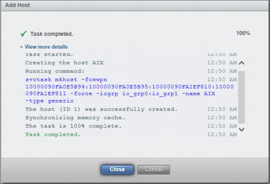
Figure 5-35 Details of adding the AIX host
5. To add a Red Hat host, restart the wizard and add the Red Hat information. Figure 5-36 shows adding a host only for I/O group 1.

Figure 5-36 Add RedHat host to one IO group
6. Click Add Host to create the host.
7. The next step is to create volumes for the hosts. Click Create Volumes in the Volumes menu and select a preset and then the disk group (Figure 5-37) to create four volumes for the AIX host.

Figure 5-37 Creating 4 volumes
8. After entering the volume detail data, click Advanced.
9. The Advanced Settings window opens (Figure 5-38). Volumes are presented to the host by one I/O group. A cluster with two or more I/O groups will, by default, automatically balance the volumes over all I/O groups. The AIX host can access both I/O groups in this example setup. Therefore, the volumes for the AIX host can be auto-balanced over the two I/O groups. This is the default setup.

Figure 5-38 Default volume locality settings.
10. The volume information shows four AIX volumes distributed over both I/O groups. The header in the next figure was altered to show the caching I/O group. The caching I/O group presents the volume to the host, as shown in Figure 5-39.

Figure 5-39 Volumes and caching I/O group
11. The next step creates volumes for the Red Hat host (RedHat). The Red Hat host is attached only to I/O group 1 and therefore in the advanced settings the caching I/O group is set to I/O group 1. Figure 5-40 shows this I/O group (io_grp1) selection.

Figure 5-40 Limiting access to I/O group 1
12. The volume information shows that the four added RedHat volumes are presented by I/O group 1 to the host (Figure 5-41).

Figure 5-41 Volumes and caching I/O group
When mapping a volume on a scaled cluster to host, the modify host mappings window opens. You must specify two selections:
– I/O Group: The list gives you the possibility to choose all, or a dedicated I/O group.
– Host: This list contains all defined hosts.
13. Figure 5-42 shows the I/O group list selection.

Figure 5-42 Host mapping I/O group and host selection
14. The selection for the AIX host is All I/O Groups, because AIX is connected two both I/O groups. For RedHat, select io_grp1 (Figure 5-43), because RedHat is attached only to io_grp1.

Figure 5-43 Select I/O group 1 for a host connect to I/O group 1 only
Crating volumes, adding hosts, and mapping volumes, the host in a FlashSystem V9000 scaled-out configuration needs planning on the host connections to the I/O groups. This example of the AIX host and the Red Hat host shows these planning steps.
5.11 Concurrent code load in a scaled out system
This section demonstrates the FlashSystem V9000 software update. Before you start a system update, be sure that the system has no problems that might interfere with a successful update. When the System uses HyperSwap volumes, make sure that the all HyperSwap volumes relationship status is online using the lsrcrelationship command. Hosts need to be configured with multipathing between the nodes of the accessing I/O group or groups when using HyperSwap.
|
Note: The software release notes contain the current information about the update.
|
The update process is described in 9.5.3, “Update software” on page 382. This next section has a brief description of the update on a FlashSystem V9000 scaled out system.
Figure 5-44 shows a FlashSystem V9000 full scaled out cluster using four building blocks and four additional V9000 FlashSystem enclosures (in total, eight controller nodes and eight FlashSystem enclosures).

Figure 5-44 Full scaled out and scaled up FlashSystem V9000
The FlashSystem V9000 update consists of three phases, with different steps for each phase:
1. Phase 1: FlashSystem V9000 control enclosures
a. Update of one controller node per I/O group, one controller at a time
b. Pause for approximately 30 minutes for host path discovery, hosts have to reconnect to the updated controller nodes
c. Update of the other controller node of an I/O group, one controller at a time
2. Phase 2: FlashSystem V9000 storage enclosures software
a. Update of one canister per storage enclosure, all in parallel
b. Update of the other canister of a storage enclosure, all in parallel
3. Phase 3: FlashSystem V9000 storage enclosures hardware
a. Updates Batteries, Flashcards, and so on
The update takes about 2.5 hours for a cluster with one building block. You can add 10 - 15 minutes per additional node. Adding FlashSystem V9000 storage enclosures does not increase the amount of time to the update, because they are all updated in parallel.
Complete the following steps:
1. To start the concurrent code load (CCL), click Settings → System → Update System → Update.
2. The update wizard opens (Figure 5-45). Provide a name for the test utility and the update package. Use the folder buttons to select the correct file names and click Update.

Figure 5-45 Update system file selection
3. You are prompted whether you want the update to be automatic or manual. Select Automatic update (Figure 5-46) and then click Finish.

Figure 5-46 Automatic or manual update
The files are uploaded to FlashSystem V9000. A progress bar shows the status of the upload (Figure 5-47).

Figure 5-47 CCL upload progress bar
4. After uploading the files, the GUI will show the overall progress bar. It takes one to two minutes after uploading the files before the overall progress status is shown. Figure 5-48 shows the information for an eight node, four I/O groups cluster.

Figure 5-48 Overall Progress
At the starting point of the update, all eight nodes and the system part, which also includes the FlashSystem V9000 enclosures, are in state Not updated. Then all eight nodes are updated one by one, starting with the second node of each I/O group. After one node of every I/O group has been updated, the update will pause for approximately 30 minutes for host path discovery. Then the other nodes are updated.
5. Figure 5-49 shows the progress on the first node updating, which is node 2 in this example.

Figure 5-49 Updating first node, the second node of the first I/O group
Figure 5-50 shows the progress on the second node updating, which is node 4 in this example.

Figure 5-50 Second node updating, which is node 4
Figure 5-51 shows the progress on the third node updating, which is node 6 in
this example.
this example.

Figure 5-51 Third node updating, which is node 6
Figure 5-52 shows the progress on the fourth node updating, which is node 8 in this example.

Figure 5-52 Fourth node updating, which is node 8
After updating half of all nodes, one node of every I/O group, the update pauses for approximately 30 minutes for host path discovery. Figure 5-53 shows the next node to be updated and the state of waiting for path discovery. This is the configuration node, which is node 1 in this example.

Figure 5-53 Pausing for host path discovery
After the start of configuration node updated, a node failover message is displayed (Figure 5-54).

Figure 5-54 CCL node failover due to update of the configuration node
Figure 5-55 shows the progress on the fifth node updating, which is the configuration node, currently node 1 in this example.

Figure 5-55 Fifth node updating, which is node 1
Figure 5-56 shows the progress on the sixth node updating, which is node 3 in this example.

Figure 5-56 Sixth node updating, which is node 3
Figure 5-57 shows the progress on the seventh node updating, which is node 5 in this example.

Figure 5-57 Seventh node updating, which is node 5
Figure 5-58 shows the progress on the eighth node updating, which is node 7 in this example.

Figure 5-58 Eighth node updating, which is node 7
6. After all of the FlashSystem controller nodes are updated, the FlashSystem storage enclosure software is updated. All FlashSystem storage enclosures are updated on parallel, meaning at the same time. First the FlashSystem enclosures are updated (Figure 5-59).

Figure 5-59 FlashSystem storage enclosure canister update
7. Figure 5-60 shows the last part of the update, the FlashSystem V9000 firmware update of all other components, such as flash modules, batteries, and so on.

Figure 5-60 FlashSystem enclosures batteries, flash modules, and other hardware parts update
8. When the update is complete, a message indicates that FlashSystem V9000 is running the most current software (Figure 5-61).

Figure 5-61 FlashSystem V9000 running up-to-date software
All FlashSystem V9000 controller nodes and storage enclosures are now updated to the current software level.
..................Content has been hidden....................
You can't read the all page of ebook, please click here login for view all page.