


Securing IBM z/OS HyperSwap communication with IBM Copy Services Manager
The scenario in this chapter describes how to configure secure TCP/IP communication between IBM z/OS HyperSwap function and an IBM Copy Services Manager (CSM) server instance.
In addition to managing storage replication, IBM Copy Services Manager can be used to initiate a planned HyperSwap operation. The configuration described in this chapter enables z/OS HyperSwap to communicate with CSM securely using Transport Layer Security (TLS). z/OS HyperSwap can be also triggered or initiated with no CSM involvement.
This chapter describes the following topic:
7.1 IBM z/OS HyperSwap
IBM z/OS HyperSwap function has been designed to enhance system high availability by masking storage failures in a (IBM DS8000 series) Metro Mirror configuration. HyperSwap is a z/OS component which manages storage access paths on an IBM Z server. If there is an I/O error in the primary set of volumes (for example, a storage subsystem failure), HyperSwap automatically swaps I/O to a secondary set of volumes (Metro Mirror target) with little to no impact to the application.
7.1.1 Introduction
IBM Copy services Manager (CSM) manages z/OS HyperSwap using a HyperSwap session. For Copy Services Manager, the HyperSwap session is managed as a Metro Mirror session. CSM manages the z/OS HyperSwap function in the z/OS systems for controlled swaps.
IBM Copy Services Manager supports enabling the following session types with HyperSwap capabilities:
•Basic HyperSwap
•Metro Mirror
•Metro-Global Mirror
•Multi-target session types:
– Metro Mirror - Metro Mirror
– Metro Mirror - Global Mirror
– Metro Mirror - Global Mirror with Practice
7.1.2 z/OS HyperSwap overview
This section provides a high-level overview of the z/OS HyperSwap functionality. For additional information and details about how to configure z/OS HyperSwap, see the IBM Redpaper™ publication IBM DSS 8880 and z Systems Synergy, REDP-5186.
A typical deployment scenario is shown in Figure 7-1.
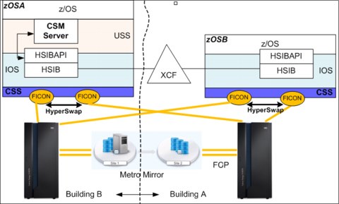
Figure 7-1 z/OS Basic HyperSwap in a Parallel Sysplex
In the course of the actual swap operation, HyperSwap is responsible to issue all necessary Copy Services commands to perform the complete failover to H2. This failover also leads to the Metro Mirror state change of the H2 volumes from secondary DUPLEX to primary SUSPENDED.
7.1.3 Securing TCP/IP communication for CSM: An overview
IBM Copy Services manager can be deployed on several platforms. For supported platforms check the current information at IBM Support.
CSM communicates with the z/OS HyperSwap using two methods:
•Java Native Interface (JNI)
•TCP/IP
Communication using JNI
For most common z/OS environments, IBM Copy Services Manager server code runs in a z/OS image (in an address space) and utilizes the underlying Unix System Services (USS).
When the CSM server instance (code) runs inside the same z/OS image that has z/OS HyperSwap configured (or in a z/OS image part of a Parallel Sysplex, as shown in Figure 7-1 on page 152), the CSM server communicates with the z/OS HyperSwap through the HyperSwap API (HSIBAPI z/OS address space) directly (no TCP/IP communication), using the Java Native Interface (JNI). In this case, no additional security is required for this type of communication.
Communication using TCP/IP
In a configuration where the CSM server runs outside the scope of the z/OS HyperSwap configuration, the communication between the CSM server and the z/OS HyperSwap is performed via TCP/IP. In this case, regardless of the relative location of the platform on which the CSM server runs, communication (via TCP/IP) with the z/OS HyperSwap address space must be secured.
The CSM server, outside the scope of the z/OS HyperSwap, can be deployed:
•In a different z/OS image, not part of a Parallel Sysplex
•In a z/OS image in a different Parallel Sysplex
•In a system not running z/OS (AIX, Linux, or Microsoft Windows, or the DS8000 HMC)
Scenario
Consider the following DR sample scenario, presented in Figure 7-2 on page 154:
•In the primary site, the z/OS LPAR is configured with HyperSwap over the MM relationship between two storage subsystems (H1 and H2). The z/OS LPAR also runs the active (primary) instance of the CSM server.
•The active (primary) CSM Server replicates to the standby (backup) CSM server hosted on a system in the DR site, outside the z/OS or the Parallel Sysplex. The Standby CSM server can be installed and configured on an “open” system (AIX, Linux, or Windows) located in a DR site (Site 3 in the example).
|
Tip: After a planned or unplanned HyperSwap, the active volumes are swapped from H1 to H2, and CSM remains passive and not involved. HyperSwap notifies CSM about the session state change after the HyperSwap operation is completed.
|

Figure 7-2 Basic MGM scenario using Copy Services Manager
|
Tip: The standby (backup) CSM server can also be configured to run on a DS888x Hardware Management Console (HMC)1 that manages the storage subsystems located in the DR site (Site 3).
|
1 There may be certain limitations for setting up secure communication between the z/OS HyperSwap and a CSM server instance running on the DS888x HMC. Check the latest DS888x HMC and CSM documentation before you configure this HMC as a CSM server.
•Under normal circumstances, the active CSM server is the primary CSM server, and it is used to manage the z/OS HyperSwap configured on the production z/OS LPAR.
Because the CSM (server) and the HyperSwap address run on the same z/OS image, CSM uses the Java Native Interface (JNI) to communicate to the z/OS HyperSwap address space.
•For high availability, the CSM configuration data is replicated over a TCP/IP connection to the standby (backup) CSM server running in the DR site (Site 3).
•The DS8000 in the DR site (Site 3) is configured for Global Mirror. The z/OS LPAR in the DR site is not activated when production runs in the primary z/OS LPAR.
•In case the primary (production) location becomes unavailable (including the primary CSM server), the standby (backup) CSM server must be activated to manage the replication and to make available the H3 copy (Global Mirror) in the DS8000 located in the DR site (Site 3).
•When the CSM server running in the DR site (Site 3) becomes active, it should be used to manage the replication even after the primary site becomes available (z/OS HyperSwap), and until proper recovery is performed. Recovery may require to resynchronize (Site 3 to Site 1) data between the CSM servers (active CSM server located in DR site, which has the latest CSM data, and the CSM server in the primary site).
In this situation, the communication between the (now active) CSM instance in the DR location and the z/OS HyperSwap in the Primary site (Site 1) must be secured (encrypted).
Why use AT-TLS?
Because the z/OS HyperSwap has not been coded to support encrypted communication, the z/OS Application Transparent Transport Layer Security (AT-TLS) facility can be used to provide encrypted data transfer between the active CSM server and the z/OS HyperSwap.
7.1.4 Securing communication between z/OS HyperSwap and the CSM Server
This section describes the basic configuration steps for securing TCP/IP communication between the z/OS HyperSwap (identified as the SERVER role) and the IBM Copy Services Manager Server (identified as the CLIENT role).
|
Note: For our scenario we have deployed a standalone CSM server running a Linux (x86_64) platform.
|
Overview
The z/OS HyperSwap has been enhanced through the HyperSwap Sockets Server (BHIHSRV z/OS address space) to allow IBM Copy Services Manager to connect to the HyperSwap address space using sockets, in addition to the Java Native Interface (JNI).
This enables a CSM instance running on z/OS in one sysplex or a standalone z/OS image to manage HyperSwap sessions running one or more other sysplexes, and also allows HyperSwap management from a CSM instance running on a non-z/OS system (AIX, Windows, or Linux).
Scenario considerations
For the scenario presented in Figure 7-2 on page 154 we need to secure TCP/IP communication between the CSM instance running on a non-z/OS operating system located in Site 3 (activated after a CSM failover) and the z/OS HyperSwap. This configuration is shown in Figure 7-3.

Figure 7-3 z/OS HyperSwap management from DR CSM instance
Secure TCP/IP communication configuration is needed if we want to manage the z/OS HyperSwap in Site 1 before the CSM instance is recovered to the initial server running on z/OS (CSM active/standby configuration is shown in Figure 7-2 on page 154).
The z/OS SSL/TLS infrastructure must be configured prior to using encrypted TCP/IP communication between the z/OS HyperSwap and the CSM instance in Site 3.
Terminology
This section introduces general terminology that is useful in providing understanding of the parties and entities involved in building and serving the secure communication context.
Client-server model
The client-server model has the following roles:
•Client role: A piece of a computer application that communicates with another entity (server role) that provides access to some function or feature (data) that is requested by the client. The server responds by providing the services and data requested. The client can be:
– A user (person) that interacts with some kind of computer interface used to request information.
– Another application in an environment with automated actions.
•Server role: A piece of computer application that listens to client requests and responds with the requested data.
Security: identity management
Identity management in terms of security includes the following elements:
•Identity: When two parties need to communicate (client and server roles), the first requirement is to identify with each other. The client must present some kind of identity form to the server, and the server must be able to identify itself to the client. The identity is presented in the form of a Digital Certificate.
•Certificate Authority: To establish the parties’ identities, some kind of third party that can guarantee the identity presented by each party may be required. The third party is trusted by the parties that need to identify with each other. The Certificate Authority is used in the initial phase of the communication to establish trust.
•When a party presents its identity (Digital Certificate), the other party checks the Digital Certificate by referring to the Certificate Authority.
•Digital Certificate: A Digital Certificate conforms to a standard format (for example, x.509) and contains information about the identity that it represents. In addition to the public key of the identity that it represents, the certificate contains an expiration date, information about the identity (organization, division, and so on), issuer information, and key fingerprint and algorithm information.
•Key Ring: A collection of certificates (identities) available to a party for use during the secure communication process.
Security: Data privacy and data integrity
Data privacy is achieved by encrypting the data sent over a communication channel (between the client and the server). Data integrity is achieved by providing data digest mechanisms, for example by using hashing algorithms (one way hashing functions):
•Cypher/decipher: Cypher is a mathematical method used to encrypt the data (data -> code). Decipher is the reverse action used to retrieve the data from the code.
•Encryption/decryption: Encryption is the process converting some kind of data into a form (code) that cannot be (easily) understood by a third party that accidentally intercepts a copy of the encrypted data. Decryption is the process of extracting the data from the encrypted format (code). Over a communication channel, the data is encrypted at its source and decrypted at its destination.
•Integrity: To ensure that the data reaches its destination unaltered (unchanged in any form), additional information (data digest generated at source) must be provided at he destination. This information is compared at destination with the digest of the data (generated at destination) to ensure integrity.
Client and server roles (client-server modes) applied to our environment
|
Important: In this model of deployment (IBM z/OS HyperSwap managed by Copy Services Manager), for securing the client-server communication using TLS, the HyperSwap Manager (part of z/OS) plays the SERVER role, while the CSM server instance plays the CLIENT role.
|
Configuration FLOW
A local Certificate Authority is used to sign the HyperSwap Manager (server role) certificate:
•The RACF (Resource Access Control Facility) is used to generate the Certificate Authority (local to the z/OS image where the HyperSwap address space runs). The z/OS (local) Certificate Authority (CA) fits the purpose to provide the client (CSM instance) with the level of trust required to control the z/OS HyperSwap server.
•The Certificate Authority provides a self-signed certificate (trusted root certificate). The self-signed certificate is generated using RACF. The CA’s self-signed certificate is provided to the client (the CSM server) that needs to verify the certificate (identity) of the party involved in communication (the HyperSwap Manager identity).
|
Tip: A publicly available certificate authority can be used to sign the z/OS HyperSwap server certificate; however, this would generate unnecessary administrative burden for the limited function that must be served (authentication and securing communication between the CSM instance and the z/OS HyperSwap Manager).
|
•RACF is also used to generate the HyperSwap Manager’s key pair (public and private keys for the server role). The HyperSwap Manager (server) certificate is signed using the CA’s trusted root certificate (previously generated).
•Certificates (CA’s certificate and the HyperSwap Manager certificate) are stored in a key ring that is made available to the AT-TLS policy manager. The key ring a is used by AT-TLS on behalf of the parties involved in the communication (for authentication and data encryption).
•AT-TLS policies must be configured and installed.
AT-TLS overview
Socket applications that have not been coded to support encrypted communication send and receive clear text over the socket.
•In z/OS, AT-TLS (Application Transparent Transport Layer Security) provides TLS support for existing clear-text (no encryption) socket applications without requiring any application changes (re-coding).
•The Transport Layer Security (TLS) protocol provides transport layer security (authentication, integrity, and confidentiality) for a secure connection between two applications.
•The TLS protocol begins with a handshake, in which the two applications (client and server) agree on a cipher suite. A cipher suite is composed of cryptographic algorithms to be used for authentication, session encryption, and hashing (digital fingerprinting).
•After the client and server applications have negotiated a cipher suite, they authenticate each other and generate a session key. The session key is used to encrypt and decrypt all data traffic sent between client and server.
•Applications that have not been coded to use the SSL/TLS libraries (such as z/OS HyperSwap) are unaware of the encrypted traffic carried on their behalf by AT-TLS.
•In addition, support is provided for applications that require awareness of AT-TLS for status or to control the negotiation of security.
AT-TLS is policy-driven, managed by a policy agent (PAGENT):
•AT-TLS provides application-to-application security using policies. The policies are defined and loaded into the stack by policy agent (PAGENT).
•When AT-TLS is enabled and a newly established connection is first used, the TCP layer of the stack searches for a matching AT-TLS policy.
•If no policy is found, the connection is made without AT-TLS involvement. If a policy is found, a sequence of activities is generated to catty out encrypted traffic, similar to the one illustrated in Figure 7-4.

Figure 7-4 AT-TLS basic flow
This diagram illustrates the following flow:
1. The client connection to the server gets established in the clear (no security, TCP handshake only).
2. The server sends data in the clear and the TCP layer queues it.
3. The TCP layer invokes System SSL to perform a TLS handshake under the identity of the server, using policy information.
4. The TCP layer invokes System SSL to encrypt the queued data and sends it to the client.
5. The client then sends encrypted data and the TCP layer invokes System SSL to decrypt the data.
6. The server receives data in the clear.
For more information on z/OS AT-TLS, see the Redbook IBM z/OS V2R1 CS TCP/IP Implementation Volume 4: Security and Policy-Based Networking, SG24-8099.
7.1.5 Generating a self-signed (CA) certificate in z/OS
This certificate represents the local certificate authority (CA) and is used as a CA certificate.
To create a RACF key ring, you must first generate a RACF CA certificate and a personal certificate for IBM z/OS Basic HyperSwap, then connect the certificates to the key ring.
A RACF key ring is connected to a set of personal certificates and trusted certificates that are stored in the RACF database. The RACF command RACDCERT is used to create and delete key rings and to connect or disconnect certificates to the key rings
To create a RACF key ring to be used by AT-TLS on behalf of IBM z/OS Basic HyperSwap, complete the following steps:
1. We use RACF as a local Certification Authority. We generate a RACF certificate authority (CA) certificate as shown in Example 7-1.
Example 7-1 Generating the CA certificate (self signed)
RACDCERT CERTAUTH GENCERT -
SUBJECTSDN (OU('ITSO CSM Certificate Authority') -
O('ITSO') -
C('US')) -
KEYUSAGE(HANDSHAKE DATAENCRYPT DOCSIGN CERTSIGN) -
WITHLABEL('CSM Local Certificate Authority')
2. Next, we export this certificate to a data set so that we can use it on the system where the IBM Copy Services Manager server is running, as shown in Example 7-2.
|
Note: This data set (file) will be later transferred to the CSM server (which plays the client role for the z/OS HyperSwap server in this setup) to be used to verify the z/OS HyperSwap Manager (server) identity.
|
Example 7-2 RACF commands to export the CA certificate to a data set
RACDCERT EXPORT (LABEL('CSM Local Certificate Authority')) -
CERTAUTH DSN('CSM.LOCCERTA.CERT') -
FORMAT(CERTDER)
3. We run the RACF commands shown in Example 7-3 to refresh and ensure that the certificate is in storage.
Example 7-3 Sample RACF SETR commands
SETR CLASSACT(DIGTCERT)
SETR RACLIST(DIGTCERT)
SETR RACLIST(DIGTCERT) REFRESH
RACF is also used to generate the personal certificate that will be used for the z/OS HyperSwap Manager and the CA certificate is used to sign the personal certificate.
4. We generate a personal certificate for the IBM z/OS Basic HyperSwap server.This certificate identifies the instance of z/OS HyperSwap Manager. This certificate is presented to the partner application during the SSL handshake (CSM instance in this case).
This certificate must be associated with the user ID under which the z/OS HyperSwap Manager is running.
Finding the ID for HyperSwap
To find the ID, complete the following steps:
1. To identify the user under which the z/OS HyperSwap is running, use the command shown in Example 7-4.
Example 7-4 Identifying the user for HyperSwap
RLIST STARTED HSIB STDATA
CLASS NAME
----- ----
STARTED HSIB*.** (G)
LEVEL OWNER UNIVERSAL ACCESS YOUR ACCESS WARNING
----- -------- ---------------- ----------- -------
00 HSIB NONE NONE NO
INSTALLATION DATA
-----------------
NONE
APPLICATION DATA
----------------
NONE
AUDITING
--------
FAILURES(READ)
NOTIFY
------
NO USER TO BE NOTIFIED
STDATA INFORMATION
------------------
USER= HSIB
GROUP= SYS1
TRUSTED= NO
PRIVILEGED= NO
TRACE= NO
READY
2. The following Example 7-5 shows how to use a RACF command to generate the personal certificate for z/OS HyperSwap that is running under user ID HSIB.
Example 7-5 Generating the personal certificate for the HyperSwap user ID
RACDCERT ID(HSIB) GENCERT -
SUBJECTSDN(CN('CSM Client') -
OU('Hyperswap Server') -
O('CSM') -
C('US')) -
WITHLABEL('Hyperswap Manager') -
SIGNWITH(CERTAUTH LABEL('CSM Local Certificate Authority')) -
KEYUSAGE(HANDSHAKE DATAENCRYPT DOCSIGN)
3. We create a RACF key ring and connect the certificates to the key ring. The key ring is needed by AT-TLS. The RACF key ring must be associated with a user ID (in this case, the HSIB user ID). The key ring must have a name (in this case, csmkeyring, as shown in Example 7-6).
Example 7-6 Creating the key ring
RACDCERT ID(HSIB) ADDRING(csmkeyring)
READY
4. The z/OS HyperSwap Manager personal certificate must be connected to the key ring together with the CA certificate, as shown in Example 7-7.
Example 7-7 Adding the certificate to the key ring
RACDCERT ID(HSIB) CONNECT(LABEL('Hyperswap Manager') RING(csmkeyring) default)
READY
RACDCERT ID(HSIB) CONNECT(CERTAUTH LABEL('CSM Local Certificate Authority') RING(csmkeyring))
READY
5. We must allow user ID HSIB permission to READ the key ring, as shown in Example 7-8.
|
Note: Before allowing user ID permission to read the key ring, you may need to define the IRR.DIGTCERT.LISTRING to class FACILIY:
RDEFINE FACILITY IRR.DIGTCERT.LISTRING UACC(NONE)
|
Example 7-8 Allowing user ID READ permission to the FACILITY class
PERMIT IRR.DIGTCERT.LISTRING CLASS(FACILITY) ID(HSIB) ACCESS(READ)
ICH06011I RACLISTED PROFILES FOR FACILITY WILL NOT REFLECT THE UPDATE(S) UNTIL A SETROPTS REFRESH IS ISSUED
READY
SETR RACLIST(FACILITY DIGTCERT) REFRESH
ICH14063I SETROPTS command complete.
READY
6. Complete the following verifications:
a. We verify the CA certificate, as shown in Example 7-9.
Example 7-9 Verifying the certificate authority
RACDCERT LIST(LABEL('CSM Local Certificate Authority')) CERTAUTH
Digital certificate information for CERTAUTH:
Label: CSM Local Certificate Authority
Certificate ID: 2QiJmZmDhZmjgcPi1EDTloOBk0DDhZmjiYaJg4GjhUDBpKOIlpmJo6hA
Status: TRUST
Start Date: 2016/11/02 23:00:00
End Date: 2017/11/03 22:59:59
Serial Number:
>00<
Issuer's Name:
>OU=ITSO CSM Certificate Authority.O=ITSO.C=US<
Subject's Name:
>OU=ITSO CSM Certificate Authority.O=ITSO.C=US<
Signing Algorithm: sha256RSA
Key Usage: CERTSIGN
Key Type: RSA
Key Size: 2048
Private Key: YES
Ring Associations:
Ring Owner: HSIB
Ring:
>csmkeyring<
READY
b. We verify the personal certificate for the z/OS HyperSwap server as shown in Example 7-10.
Example 7-10 Personal certificate for z/OS HyperSwap server
RACDCERT LIST(LABEL('Hyperswap Manager')) ID(HSIB)
Digital certificate information for user HSIB:
Label: Hyperswap Manager
Certificate ID: 2QTI4snCyKiXhZmipoGXQNSBlYGHhZlA
Status: TRUST
Start Date: 2016/11/09 00:00:00
End Date: 2017/11/09 23:59:59
Serial Number:
>05<
Issuer's Name:
>OU=ITSO CSM Certificate Authority.O=ITSO.C=US<
Subject's Name:
>CN=CSM Client.OU=Hyperswap Server.O=CSM.C=US<
Signing Algorithm: sha256RSA
Key Usage: HANDSHAKE
Key Type: RSA
Key Size: 2048
Private Key: YES
Ring Associations:
Ring Owner: HSIB
Ring:
>csmkeyring<
READY
c. And we check the key ring, as shown in Example 7-11.
Example 7-11 Listing the key ring
RACDCERT LISTRING(csmkeyring) ID(HSIB)
Digital ring information for user HSIB:
Ring:
>csmkeyring<
Certificate Label Name Cert Owner USAGE DEFAULT
-------------------------------- ------------ -------- -------
Hyperswap Manager ID(HSIB) PERSONAL YES
CSM Local Certificate Authority CERTAUTH CERTAUTH NO
READY
7.1.6 Preparing the CSM server for secure communication with HyperSwap
|
Tip: The CSM server in DR site has been deployed on a Linux (x86_64) platform. The CSM installation provides all the tooling required to perform key and certificate management for the CSM server.
Important: Starting with CSM 6.1.5 the z/OS HyperSwap server certificate can be imported directly into CSM GUI during the Host Connection setup procedure. If your CSM server is at 6.1.5 or later, the steps in this section can be skipped.
|
Complete the following steps to prepare the CSM server:
1. Transfer the CA certificate to the CSM server (in Site 3) and add it to the CSM server key store configuration:
a. Place the certificate that was exported in Step 2 on page 159 in the z/OS UNIX System Services hierarchical file system (HFS) by using the OPUT command shown in Example 7-12. Use the BINARY option.
Example 7-12 OUTPUT command example
OPUT 'CSM.LOCCERTA.CERT' '/u/myuser/sc30.cert' BINARY
b. Log on to the CSM instance (in Site 3) and transfer the CA certificate file on the local file system. Use binary FTP to download. We have transferred it into the CSM directory tree, as shown in Example 7-13.
Example 7-13 CA certificate transferred to CSM server in Site 3
[root@csmserver wlp]# pwd
/opt/IBM/CSM/liberty/wlp
[root@csmserver wlp]# ls -l *cert
-rw-r--r-- 1 root root 910 Jan 23 18:31 sc30.cert
c. Create a Java Key Store (JKS - .jks file type) file and import the CA certificate into the JKS. The JKS will be supplied to the CSM server for verifying the identity for the z/OS HyperSwap server it has to connect to.
d. Identify the ikeyman utility delivered with the IBM Java (in our Linux installation there is one installed together with the IBM Copy Services Manager code), as shown in Example 7-14.
Example 7-14 Identifying the ikeyman utility
[root@csmserver ~]# find /opt -name ikeyman
/opt/IBM/CSM/liberty/wlp/IBM/Java/jre/bin/ikeyman

Figure 7-5 The ikeyman application GUI
f. Initiate the creation of a new Key Database file, as shown in Figure 7-6.

Figure 7-6 Creating a new Key Database file
g. Define the name and location of the Key Database file, as shown in Figure 7-7. The Key Database file will be later copied in a location suitable for the CSM server.

Figure 7-7 The key Database file
h. Supply a password for accessing the Key Database, as shown in Figure 7-8.

Figure 7-8 Protecting the Key Database with a password
i. Specify the type of certificate you want to add (import) to the newly created Key Database. We want to add a signer certificate (CA certificate), as shown in Figure 7-9.

Figure 7-9 Selecting the type of certificate you want to add (import)
j. Import the CA certificate from the file transferred earlier (b on page 163) into the Key Database, as shown in Figure 7-10.

Figure 7-10 Importing the CA certificate
k. The imported certificate is shown in Figure 7-11.

Figure 7-11 Imported CA certificate
l. Check the details by clicking the View/Edit button. The window shown in Figure 7-12 opens. Compare.

Figure 7-12 Certificate details
You can compare the certificate details with the information shown in z/OS (Example 7-9 on page 161).
2. After you close the ikeyman application, you can transfer (copy) the Key Database file (zosTrust.jks) to the following location on the CSM server (default install tree for CSM server for Linux on x86_64):
/opt/IBM/CSM/liberty/wlp/usr/servers/csmServer/etc
Check the file size and date:
cd /opt/IBM/CSM/liberty/wlp/usr/servers/csmServer/etc/
ls -l zosTrust.jks
-rw-r--r-- 1 root root 978 Jan 23 19:51 zosTrust.jks
3. Restart the CSM server to pick up the configuration changes:
/opt/IBM/CSM/stopAuth.sh
/opt/IBM/CSM/stopCSM.sh
/opt/IBM/CSM/startAuth.sh
/opt/IBM/CSM/startCSM.sh
7.1.7 Configuring AT-TLS on z/OS
In preparation for enabling secure communications for the z/OS HyperSwap, we need to configure AT-TLS and the Policy Agent.
In this section, we use the z/OS Management Facility (z/OSMF) for configuring secure TCP/IP communication between the z/OS HyperSwap and the managing CSM server (CSM server running outside z/OS).
The present scenario describes how to create the Application Transparent Transport Layer Security (AT-TLS) policy file and upload it to the required z/OS systems.
For more information about AT-TLS, view the introduction to AT-TLS presentation.
|
Important: The assumption in this chapter is that AT-TLS is already installed on your system. Thus, the steps outlined here cover only the creation of the policy file:
•For any z/OS LPARs where you want to configure AT-TLS, you must ensure that the TCP/IP profile is updated to enable AT-TLS and that the policy agent (PAGENT) is started.
•To configure AT-TLS in the TCP/IP profile, issue the TCPCONFIG TTLS command. For more information about the TCPCONFIG statement or to start PAGENT, see the z/OS Communications Server IP Configuration Reference V2R2, SC27-3651.
•This policy was created using the IBM Configuration Assistant for z/OS Communications Server V2R3 (available as a task in z/OSMF).
|
Complete the following steps:
1. Log on to the z/OS Management Facility on our system, as shown in Figure 7-13 on page 169.
|
Note: Even though the z/OSMF runs on a particular z/OS image (and is accessed through an IP address active on that z/OS image), the AT-TLS configuration can be tailored to suit your needs by selecting the appropriate scope:
•A z/OS image (can be different from the one that runs the z/OSMF)
•A Parallel Sysplex (consisting of multiple z/OS images)
•A subset of z/OS images from a Parallel Sysplex
Understanding the scope will allow you to select the correct z/OS image to configure.
|

Figure 7-13 z/OSMF Welcome: z/OS Communications Server Configuration Assistant
2. Expand the “Configuration” menu and Select “Configuration Assistant”, and select an existing (or define a new backing store) as shown in Figure 7-14.

Figure 7-14 z/OSMF Configuration Assistant backing store
3. Select the Traffic Descriptors tab and create a new traffic descriptor as shown in Figure 7-15. The traffic descriptor tells AT-TLS which service to secure.

Figure 7-15 Creating a new Traffic Descriptor

Figure 7-16 Defining the Traffic Descriptor name
5. We define the Traffic Descriptor Details (Figure 7-17 shows the TCP/IP application and protocol details). In our environment we have chosen to use port TCP 5858 for the z/OS HyperSwap Server (this is the default port the CSM server expects to talk to).

Figure 7-17 Traffic Descriptor TCP/IP details
6. We define the key ring that will be used for securing communication (AT-TLS on behalf of the application) as shown in Figure 7-18. We have chosen to define the key ring at system image level (described in a later step).

Figure 7-18 Defining the key ring for the traffic descriptor
7. The Traffic Descriptor summary is shown in Figure 7-19.

Figure 7-19 Traffic Descriptor summary
8. Figure 7-20 shows the new Traffic Descriptor listed in the CSM_STORE.
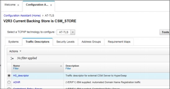
Figure 7-20 Traffic Descriptor HS_descriptor listed in the CSM_STORE
9. Next we start to configure the system(s) as shown in Figure 7-21.

Figure 7-21 Starting Systems configuration
10. We define a z/OS image as shown in Figure 7-22. If you need to define a Parallel Sysplex (or a group of systems) you need to add a z/OS Group.

Figure 7-22 Adding a z/OS System image (single system)
11. We define the z/OS System image (running z/OS V2R3) and the key ring (to be used by AT-TLS at System image level) as shown in Figure 7-23 on page 175. When he Configuration Assistant prompts for configuring a TCP/IP Stack we proceed to the next step shown in Figure 7-24 on page 175.
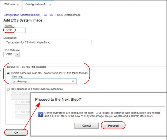
Figure 7-23 Defining system details: name, z/OS release and key ring
12. We define the TCP/IP Stack configured on our system, as shown in Figure 7-24.

Figure 7-24 Configuring a TCP/IP Stack
13. For the TCP/IP stack previously defined we need to add connectivity rules as prompted in Figure 7-25.

Figure 7-25 Configuration Assistant prompt for connectivity rules
14. The Configuration Assistant next prompts for starting the connectivity rules wizard, as shown in Figure 7-26.

Figure 7-26 Connectivity rules wizard prompt
15. The Connectivity Rule wizard is started as shown in Figure 7-27 on page 177. We define a name for the Connectivity Rule and traffic endpoints information.
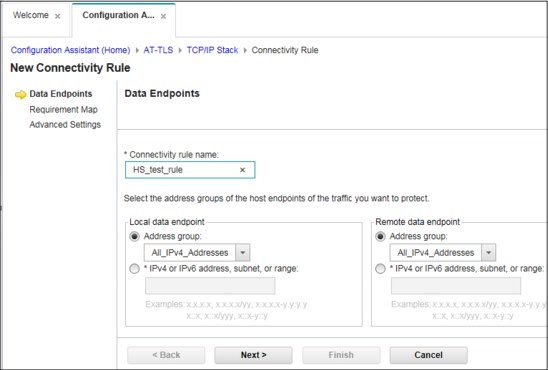
Figure 7-27 Connectivity Rule wizard
16. After defining traffic endpoints we define the traffic descriptor to be used for this rule, as shown in Figure 7-28.

Figure 7-28 Selecting Traffic Descriptor for the Connectivity Rule
17. We enter the name for the Connectivity Rule, as shown in Figure 7-29.

Figure 7-29 Connectivity Rule name
18. We finalize the creation of the Connectivity rule as shown in Figure 7-30.

Figure 7-30 Finalizing the creation of the Connectivity Rule
19. Figure 7-31 shows the result for matching the Connectivity Rule previously defined with the TCP/IP stack belonging to SC30 system image.

Figure 7-31 Connectivity rule added to the configuration
20. When the configuration is complete, the Policy Agent must be made aware of the changes. Figure 7-32 shows the policy configured but not installed yet.

Figure 7-32 Backing store CSM_STORE before installing the policy
21. We initiate the policy files installation process as shown in Figure 7-33.

Figure 7-33 Initiating the installation of configuration files
22. Figure 7-34 shows the files that need to be installed.

Figure 7-34 Policy files that need to be installed

Figure 7-35 Initiating installation of files
24. We chose the location of the file on the TARGET system (SC30 in our case) and chose FTP transfer as shown in Figure 7-36.

Figure 7-36 Installing file on target system via FTP
Figure 7-37 shows the installed policy.

Figure 7-37 List of AT-TLS configuration files
Example 7-15 shows the content of the policy configuration file on our system (SC30), which is installed in the following location:
/etc/cfgasst/v2r3/SC30/TCPIP/tlsPol
Example 7-15 Installed policy file
##
## AT-TLS Policy Agent Configuration file for:
## Image: SC30
## Stack: TCPIP
##
## Created by the IBM Configuration Assistant for z/OS Communications Server
## Version 2 Release 3
## Backing Store = CSM_STORE
## Install History:
## 2017-01-24 20:40:01 : lascu to 9.12.4.211
##
## End of Configuration Assistant information
TTLSRule HS_test~1
{
LocalAddrSetRef addr1
RemoteAddrSetRef addr1
LocalPortRangeRef portR1
Direction Both
Priority 255
TTLSGroupActionRef gAct1~Basic_HS
TTLSEnvironmentActionRef eAct1~Basic_HS
TTLSConnectionActionRef cAct1~Basic_HS
}
TTLSGroupAction gAct1~Basic_HS
{
TTLSEnabled On
}
TTLSEnvironmentAction eAct1~Basic_HS
{
HandshakeRole Server
EnvironmentUserInstance 0
TTLSKeyringParmsRef keyR~SC30
}
TTLSConnectionAction cAct1~Basic_HS
{
HandshakeRole Server
TTLSCipherParmsRef cipher1~AT-TLS__Silver
TTLSConnectionAdvancedParmsRef cAdv1~Basic_HS
CtraceClearText Off
Trace 2
}
TTLSConnectionAdvancedParms cAdv1~Basic_HS
{
SSLv3 Off
HandshakeTimeout 60
SecondaryMap Off
TLSv1.2 On
}
TTLSKeyringParms keyR~SC30
{
Keyring csmkeyring
}
TTLSCipherParms cipher1~AT-TLS__Silver
{
V3CipherSuites TLS_RSA_WITH_AES_128_CBC_SHA256
V3CipherSuites TLS_RSA_WITH_AES_256_CBC_SHA256
V3CipherSuites TLS_RSA_WITH_AES_128_GCM_SHA256
}
IpAddrSet addr1
{
Prefix 0.0.0.0/0
}
PortRange portR1
{
Port 5858
}
The Configuration Assistant tab now shows the hierarchy for the configuration for our z/OS HyperSwap (see Figure 7-38).

Figure 7-38 Store hierarchy
The procedure is now complete. The SC30 host can be added to the CSM Server configuration through it’s IP address, HyperSwap USER ID and password.
..................Content has been hidden....................
You can't read the all page of ebook, please click here login for view all page.