

Architecture and technical overview
This chapter describes the overall system architecture for the IBM Power System S922 (9009-22A), the IBM Power System S914 (9009-41A), and the IBM Power System S924 (9009-42A) servers. The bandwidths that are provided throughout the section are theoretical maximums that are used for reference.
The speeds that are shown are at an individual component level. Multiple components and application implementation are key to achieving the best performance.
Always do the performance sizing at the application workload environment level and evaluate performance by using real-world performance measurements and production workloads.
Figure 2-2 on page 61, Figure 2-3 on page 62, and Figure 2-1 on page 60 show the general architecture of the Power S922, Power S914, and Power S924 servers.

Figure 2-1 Power S922 logical system diagram

Figure 2-2 Power S914 logical system diagram

Figure 2-3 Power S924 logical system diagram
2.1 The IBM POWER9 processor
This section introduces the latest processor in the IBM Power Systems product family, and describes its main characteristics and features in general.
2.1.1 POWER9 processor overview
This is the architectural design of the POWER9 processor.
The servers are offered with various numbers of cores that are activated, and a selection of clock frequencies, so IBM can make offerings at several price points, and customers can select a particular server (or servers) to fit their budget and performance requirements.
The POWER9 processor is single-chip modules (SCMs) manufactured on the IBM 14-nm FinFET Silicon-On-Insulator (SOI) architecture. Each module is 68.5 mm x 68.5 mm and contains 8 billion transistors.
As shown in Figure 2-4, the chip contains 24 cores, two memory controllers, Peripheral Component Interconnect Express (PCIe) Gen4 I/O controllers, and an interconnection system that connects all components within the chip at 7 TBps. Each core has 512 KB of L2 cache, and 10 MB of L3 embedded DRAM (eDRAM). The interconnect also extends through module and system board technology to other POWER9 processors in addition to DDR4 memory and various I/O devices.

Figure 2-4 The 24-core POWER9 processor
POWER9 processor has eight memory channels, and each channel supports up to two DDR4 DIMM slots. The Power S914 server can support up to 1 TB of memory, and the Power S922 and Power S924 servers in a two-SCM configuration can support up to 4 TB of memory.
|
Limitation: The Power S914 server in a 4-core configuration is limited to 64 GB of memory.
|
2.1.2 POWER9 processor features
The POWER9 chip provides an embedded algorithm for the following features:
•External Interrupt Virtualization Engine. Reduces the code impact/path length and improves performance compared to the previous architecture.
•Gzip compression and decompression.
•PCIe Gen4 support.
•Two memory controllers that support direct-attached DDR4 memory.
•Cryptography: Advanced encryption standard (AES) engine.
•Random number generator (RNG).
•Secure Hash Algorithm (SHA) engine: SHA-1, SHA-256, and SHA-512, and Message Digest 5 (MD5).
•IBM Data Mover Tool.
Table 2-1 provides a summary of the POWER9 processor technology.
|
Note: The total values represent the maximum of 12 cores for the POWER9 architecture. Servers that are discussed in this paper have a maximum of 16 or 20 cores per module.
|
Table 2-1 Summary of the POWER9 processor technology
|
Technology
|
POWER9 processor
|
|
Die size
|
68.5 mm × 68.5 mm
|
|
Fabrication technology
|
•14-nm lithography
•Copper interconnect
•SOI
•eDRAM
|
|
Maximum processor cores
|
12
|
|
Maximum execution threads core/module
|
8/96
|
|
Maximum L2 cache core/module
|
512 KB/6 MB
|
|
Maximum On-chip L3 cache core/module
|
10 MB/120 MB
|
|
Number of transistors
|
8 billion
|
|
Compatibility
|
With prior generation of POWER processor
|
2.1.3 POWER9 processor core
The POWER9 processor core is a 64-bit implementation of the IBM Power Instruction Set Architecture (ISA) Version 3.0, and has the following features:
•Multi-threaded design, which is capable of up to eight-way simultaneous multithreading (SMT)
•64 KB, eight-way set-associative L1 instruction cache
•64 KB, eight-way set-associative L1 data cache
•Enhanced prefetch, with instruction speculation awareness and data prefetch depth awareness
•Enhanced branch prediction that uses both local and global prediction tables with a selector table to choose the best predictor
•Improved out-of-order execution
•Two symmetric fixed-point execution units
•Two symmetric load/store units and two load units, all four of which can also run simple fixed-point instructions
•An integrated, multi-pipeline vector-scalar floating point unit for running both scalar and SIMD-type instructions, including the Vector Multimedia eXtension (VMX) instruction set and the improved Vector Scalar eXtension (VSX) instruction set, which is capable of up to 16 floating point operations per cycle (eight double precision or 16 single precision)
•In-core AES encryption capability
•Hardware data prefetching with 16 independent data streams and software control
•Hardware decimal floating point (DFP) capability
More information about Power ISA Version 3.0, see OpenPOWER: IBM Power ISA Version 3.0B.
Figure 2-5 shows a picture of the POWER9 core, with some of the functional units highlighted.

Figure 2-5 POWER9 SMT4 processor core
2.1.4 Simultaneous multithreading
POWER9 processor advancements in multi-core and multi-thread scaling are remarkable. A significant performance opportunity comes from parallelizing workloads to enable the full potential of the microprocessor, and the large memory bandwidth. Application scaling is influenced by both multi-core and multi-thread technology.
SMT enables a single physical processor core to simultaneously dispatch instructions from more than one hardware thread context. With SMT, each POWER9 core can present eight hardware threads. Because there are multiple hardware threads per physical processor core, more instructions can run at the same time. SMT is primarily beneficial in commercial environments where the speed of an individual transaction is not as critical as the total number of transactions that are performed. SMT typically increases the throughput of workloads with large or frequently changing working sets, such as database servers and web servers.
Table 2-2 shows a comparison between the different POWER processors in terms of SMT capabilities that are supported by each processor architecture.
Table 2-2 SMT levels that are supported by POWER processors
|
Technology
|
Cores/system
|
Maximum SMT mode
|
Maximum hardware threads per partition
|
|
IBM POWER4
|
32
|
Single thread
|
32
|
|
IBM POWER5
|
64
|
SMT2
|
128
|
|
IBM POWER6
|
64
|
SMT2
|
128
|
|
IBM POWER7
|
256
|
SMT4
|
1024
|
|
IBM POWER8
|
192
|
SMT8
|
1536
|
|
IBM POWER9
|
192
|
SMT8
|
1535
|
2.1.5 Processor feature codes
The Power S922 (9009-22A) server is a 2-socket server with up to 20 cores. A system can be ordered with a single processor, and a second processor can be added as a miscellaneous execution system (MES) upgrade.
Table 2-3 shows the processor feature codes (FCs) for the Power S922 server.
Table 2-3 Processor feature codes specification for the Power S922 server
|
Number of cores
|
Frequency
|
Feature code
|
|
4 cores
|
2.8 - 3.8 GHz
|
#EP16
|
|
8 cores
|
3.4 - 3.9 GHz
|
#EP18
|
|
10 cores
|
2.9 - 3.8 GHz
|
#EP19
|
The Power S914 (9009-41A) server is the entry server that supports a one-processor socket with up to eight cores.
Table 2-4 shows the processor FCs for the Power S914 server.
Table 2-4 Processor feature codes specification for the Power S914 server
|
Number of cores
|
Frequency
|
Feature code
|
|
4 cores
|
2.3 - 3.8 GHz
|
#EP10
|
|
6 cores
|
2.3 - 3.8 GHz
|
#EP11
|
|
8 cores
|
2.8 - 3.8 GHz
|
#EP12
|
The Power S924 (9009-42A) server is a powerful 2-socket server with up to 24 cores. A system can be ordered with a single processor and a second processor can be added as an MES upgrade.
Table 2-5 shows the processor FCs for the Power S924 server.
Table 2-5 Processor feature codes specification for the Power S924 server
|
Number of cores
|
Frequency
|
Feature code
|
|
8 cores
|
3.8 - 4.00 GHz
|
#EP1E
|
|
10 cores
|
3.5 - 3.9 GHz
|
#EP1F
|
|
12 cores
|
3.4 - 3.9 GHz
|
#EP1G
|
2.1.6 Memory access
The scale-out machines use industrial standard DDR4 DIMMs. Each POWER9 module has two memory controllers, which are connected to eight memory channels. Each memory channel can support up to two DIMMs. A single POWER9 module can support a maximum of 16 DDR4 DIMMs.
The speed of the memory depends on the DIMM size and placement.
Table 2-6 shows the DIMM speeds.
Table 2-6 DIMM speed
|
Registered DIMM (RDIMM) size
|
Mbps (1 DIMM per port)
|
Mbps (2 DIMMs per port)
|
|
8 GB
|
2666
|
2133
|
|
16 GB
|
2666
|
2133
|
|
32 GB
|
2400
|
2133
|
|
64 GB
|
2400
|
2133
|
|
128 GB
|
2400
|
2133
|
The Power S914 server can support up to 1 TB of memory. The Power S922 and Power S924 servers with a two-SCM configuration can operate up to 4 TB of memory.
Figure 2-6 shows an overview of the POWER9 direct attach memory.

Figure 2-6 Overview of POWER9 direct attach memory
2.1.7 On-chip L3 cache innovation and intelligent caching
Similar to POWER8, the POWER9 processor uses a breakthrough in material engineering and microprocessor fabrication to implement the L3 cache in eDRAM and place it on the processor die. The L3 cache is critical to a balanced design, as is the ability to provide good signaling between the L3 cache and other elements of the hierarchy, such as the L2 cache or SMP interconnect.
The on-chip L3 cache is organized into separate areas with differing latency characteristics. Each processor core is associated with a fast 10 MB local region of L3 cache (FLR-L3), but also has access to other L3 cache regions as a shared L3 cache. Additionally, each core can negotiate to use the FLR-L3 cache that is associated with another core, depending on the reference patterns. Data can also be cloned and stored in more than one core’s FLR-L3 cache, again depending on the reference patterns. This intelligent cache management enables the POWER9 processor to optimize the access to L3 cache lines and minimize overall cache latencies.
Here are the L3 cache features on the POWER9 processor:
•Private 10-MB L3 cache/shared L3.1.
•20-way set associative.
•128-byte cache lines with 64-byte sector support.
•10 EDRAM banks (interleaved for access overlapping).
•64-byte wide data bus to L2 for reads.
•64-byte wide data bus from L2 for L2 castouts.
•Eighty 1 Mb EDRAM macros that are configured in 10 banks, with each bank having a 64-byte wide data bus.
•All cache accesses have the same latency.
•20-way directory that is organized as four banks, with up to four reads or two reads and two writes every two processor clock cycles to differing banks.
2.1.8 Hardware transactional memory
Transactional memory is an alternative to lock-based synchronization. It attempts to simplify parallel programming by grouping read and write operations and running them like a single operation. Transactional memory is like database transactions where all shared memory accesses and their effects are either committed together or discarded as a group. All threads can enter the critical region simultaneously. If there are conflicts in accessing the shared memory data, threads try accessing the shared memory data again or are stopped without updating the shared memory data. Therefore, transactional memory is also called a lock-free synchronization. Transactional memory can be a competitive alternative to lock-based synchronization.
Transactional memory provides a programming model that makes parallel programming easier. A programmer delimits regions of code that access shared data, and the hardware runs these regions atomically and in isolation, buffering the results of individual instructions and retrying execution if isolation is violated. Generally, transactional memory enables programs to use a programming style that is close to coarse-grained locking to achieve performance that is close to fine-grained locking.
Most implementations of transactional memory are based on software. The POWER9 processor-based systems provide a hardware-based implementation of transactional memory that is more efficient than the software implementations and requires no interaction with the processor core, therefore enabling the system to operate in maximum performance.
2.1.9 Coherent Accelerator Processor Interface 2.0
IBM Coherent Accelerator Processor Interface (CAPI) 2.0 is the evolution of CAPI and defines a coherent accelerator interface structure for attaching special processing devices to the POWER9 processor bus. As with the original CAPI, CAPI2 can attach accelerators that have coherent shared memory access with the processors in the server and share full virtual address translation with these processors by using standard PCIe Gen4 buses with twice the bandwidth compared to the previous generation.
Applications can have customized functions in Field Programmable Gate Arrays (FPGAs) and queue work requests directly into shared memory queues to the FPGA. Applications can also have customized functions by using the same effective addresses (pointers) they use for any threads running on a host processor. From a practical perspective, CAPI enables a specialized hardware accelerator to be seen as an extra processor in the system with access to the main system memory and coherent communication with other processors in the system.
Figure 2-7 shows a comparison of the traditional model, where the accelerator must go through the processor to access memory with CAPI.

Figure 2-7 CAPI accelerator that is attached to the POWER9 processor
The benefits of using CAPI include the ability to access shared memory blocks directly from the accelerator, perform memory transfers directly between the accelerator and processor cache, and reduce the code path length between the adapter and the processors. This reduction in the code path length might occur because the adapter is not operating as a traditional I/O device, and there is no device driver layer to perform processing. CAPI also presents a simpler programming model.
The accelerator adapter implements the POWER Service Layer (PSL), which provides address translation and system memory cache for the accelerator functions. The custom processors on the system board, consisting of an FPGA or an ASIC, use this layer to access shared memory regions, and cache areas as though they were a processor in the system. This ability enhances the performance of the data access for the device and simplifies the programming effort to use the device. Instead of treating the hardware accelerator as an I/O device, it is treated as a processor, which eliminates the requirement of a device driver to perform communication. It also eliminates the need for direct memory access that requires system calls to the OS kernel. By removing these layers, the data transfer operation requires fewer clock cycles in the processor, improving the I/O performance.
The implementation of CAPI on the POWER9 processor enables hardware companies to develop solutions for specific application demands. Companies use the performance of the POWER9 processor for general applications and the custom acceleration of specific functions by using a hardware accelerator with a simplified programming model and efficient communication with the processor and memory resources.
2.1.10 Power management and system performance
The POWER9 scale-out models introduced new features for EnergyScaleincluding new variable processor frequency modes that provide a significant performance boost beyond the static nominal frequency. The following modes can be modified or disabled.
The default performance mode depends on the server model. For the Power S914 server (9009-41A), Dynamic Performance mode is enabled by default, and the Power S922 (9009-22A) and Power S924 (9009-42A) servers have Maximum Performance mode enabled by default. The difference in the Power S914 setup is that some servers are used in the office workspace where the extra fan noise might be unacceptable. If acoustic concern is not an issue, you can change to Maximum Performance mode.
Disable all modes
The processor clock frequency is set to its nominal value, and the power that is used by the system remains at a nominal level. This option was the default for all systems before POWER9.
Static Power Save mode
Reduces the power consumption by lowering the processor clock frequency and the voltage to fixed values. This option also reduces the power consumption of the system while still delivering predictable performance.
Dynamic Power Performance mode
Causes the processor frequency to vary based on the processor use. During periods of high use, the processor frequency is set to the maximum value allowed, which might be above the nominal frequency. Additionally, the frequency is lowered below the nominal frequency during periods of moderate and low processor use.
Maximum Performance mode
The mode enables the system to reach the maximum frequency under certain conditions. The power consumption increases. The maximum frequency is approximately 20% better than nominal.
The controls for all of these modes are available on the Advanced System Management Interface (ASMI) and can be dynamically modified.
2.1.11 Comparison of the POWER9, POWER8, and POWER7+ processors
Table 2-7 shows comparable characteristics between the generations of POWER9, POWER8, and POWER7 processors.
Table 2-7 Comparison of technology for the POWER9 processor and prior generations
|
Characteristics
|
POWER9
|
POWER8
|
POWER7+
|
|
Technology
|
14 nm
|
22 nm
|
32 nm
|
|
Die size
|
68.5 mm x 68.5 mm
|
649 mm2
|
567 mm2
|
|
Number of transistors
|
8 billion
|
4.2 billion
|
2.1 billion
|
|
Maximum cores
|
24
|
12
|
8
|
|
Maximum SMT threads per core
|
4 threads
|
8 threads
|
4 threads
|
|
Maximum frequency
|
3.8 - 4.0 GHz
|
4.15 GHz
|
4.4 GHz
|
|
L2 Cache
|
512 KB shared between cores
|
512 KB per core
|
256 KB per core
|
|
L3 Cache
|
10 MB of FLR-L3 cache per two cores with each core having access to the full 120 MB of L3 cache, on-chip eDRAM
|
8 MB of FLR-L3 cache per core with each core having access to the full 96 MB of L3 cache, on-chip eDRAM
|
10 MB of FLR-L3 cache per core with each core having access to the full 80 MB of L3 cache, on-chip eDRAM
|
|
Memory support
|
DDR4
|
DDR3 and DDR4
|
DDR3
|
|
I/O bus
|
PCIe Gen4
|
PCIe Gen3
|
GX++
|
2.2 Memory subsystem
The Power S914 server is a one-socket system that supports a single POWER9 processor module. The server supports a maximum of 16 DDR4 DIMM slots. Memory features that are supported are 8 GB, 16 GB, 32 GB, and 64 GB in 6-core and 8-core configurations that offer a maximum system memory of 1 TB. Memory speeds vary depending on the DIMM size and modules placement, as shown in Table 2-8.
|
Note: If you use the 4-core memory #EP10, the maximum number of DIMMs that are available are four, and the memory size that is allowed is 8 GB, 16 GB or 32 GB, for a maximum of 64 GB RAM.
|
The Power S922 and Power S924 servers are two-socket servers that support up to two POWER9 processor modules. The servers support a maximum of 32 DDR4 DIMM slots, with 16 DIMM slots per installed processor. Memory features that are supported are 8 GB, 16 GB, 32 GB, 64 GB, and 128 GB, enabling a maximum system memory of 4 TB. Memory speeds vary depending on the DIMM size and modules placement, as shown in Table 2-8.
Table 2-8 POWER9 memory speed
|
RDIMM size
|
Mbps (1 DIMM per port)
|
Mbps (2 DIMMs per port)
|
|
8 GB
|
2400
|
2133
|
|
16 GB
|
2666
|
2133
|
|
32 GB
|
2400
|
2133
|
|
64 GB
|
2400
|
2133
|
|
128 GB
|
2400
|
2133
|
The maximum theoretical memory bandwidth for POWER9 processor module is 170 GBps. The total maximum theoretical memory bandwidth for a two-socket system is 340 GBps.
These servers support an optional feature that is called Active Memory Expansion that enables the effective maximum memory capacity to be much larger than the true physical memory on AIX. This feature runs innovative compression and decompression of memory content by using a dedicated coprocessor to provide memory expansion up to 125%, depending on the workload type and its memory usage.
For example, a server with 256 GB RAM physically installed can effectively be expanded over 512 GB RAM. This approach can enhance virtualization and server consolidation by allowing a partition to do more work with the same physical amount of memory or a server to run more partitions and do more work with the same physical amount of memory.
2.2.1 Memory placement rules
The following memory options are orderable:
•8 GB DDR4 DRAM (#EM60)
•16 GB DDR4 DRAM (#EM62)
•32 GB DDR4 DRAM (#EM63)
•64 GB DDR4 DRAM (#EM64)
•128 GB DDR4 DRAM (#EM65)
|
Note: If you use the 4-core memory #EP10, the only memory sizes that are allowed is 8 GB (#EM60), 16 GB (#EM62) and 32 GB (#EM63).
|
All memory must be ordered in pairs, with a minimum of 32 GB for the Power S914, Power S924, and Power 922 servers that have a single processor module installed. 64 GB is the minimum for servers with two processors modules that are installed (the Power S924 and Power S922 servers) per server.
The supported maximum memory is as follows for the Power S914 server:
•One processor module installed (4-core): 64 GB (eight 8 GB DIMMS, four 16 GB DIMMs, or two 32 GB DIMMs)
•One processor module installed (6-core or 8-core): 1 TB (Sixteen 64 GB DIMMs)
The supported maximum memory is as follows for the Power S924 and the Power S922 servers:
•One processor module installed: 2 TB (Sixteen 128 GB DIMMs)
•Two processors modules installed: 4 TB (Thirty-two 128 GB DIMMs)
The basic rules for memory placement follow:
•Each FC equates to a single physical DIMM.
•All memory features must be ordered in pairs.
•All memory DIMMs must be installed in pairs.
•Each DIMM within a pair must be of the same capacity.
In general, the preferred approach is to install memory evenly across all processors in the system. Balancing memory across the installed processors enables memory access in a consistent manner and typically results in the best possible performance for your configuration. You should account for any plans for future memory upgrades when you decide which memory feature size to use at the time of the initial system order.
Figure 2-8 shows the physical memory DIMM topology for the Power S914 server.

Figure 2-8 Memory DIMM topology for the Power S914 server
For systems with a single processor module that is installed, the plugging order for the memory DIMMs is as follows (see Figure 2-9):
•Pair installation:
– The first DIMM pair is installed at Red 1 (C33 DDR0-A and C17 DDR1-A).
– The second DIMM pair is installed at Gold 2 (C36 DDR4-A and C22 DDR5-A).
– The third DIMM pair is installed at Cyan 3 (C31 DDR2-A and C15 DDR3-A).
– The fourth DIMM pair is installed at Gray 4 (C38 DDR6-A and C20 DDR7-A).
•Quad installation:
– Two fifth DIMM pairs (or quad) are installed at Red 5 (C34 DDR0-B and C18 DDR1-B) and at Cyan 5 (C32 DDR2-B and C16 DDR3-B).
– Two sixth DIMM pairs (or quad) are installed at Gold 6 (C35 DDR4-B and C21 DDR-B) and at Gray 6 (C37 DDR6-B and C19 DDR7-B).

Figure 2-9 DIMM plug sequence for the Power S914 server
More considerations:
•You may not mix 1R and 2R DIMMs on a single channel within an MCU group because they run at different DIMM data rates.
Table 2-9 lists the feature codes of the supported memory modules.
Table 2-9 Memory feature codes
|
Size
|
Feature code
|
Rank
|
|
8 GB
|
#EM60
|
1R
|
|
16 GB
|
#EM62
|
1R
|
|
32 GB
|
#EM63
|
2R
|
|
64 GB
|
#EM64
|
2R
|
|
128 GB
|
#EM65
|
2R
|
•DIMMs in the same color cells must be identical (same size and rank).
Figure 2-10 shows the physical memory DIMM topology for the Power S922 and the Power S924 servers.

Figure 2-10 Memory DIMM topology for the Power S922 and the Power S924
For the Power S922 and Power S924 servers, the plugging order for the memory DIMMS is as follows (see Figure 2-11):
•Pair installation:
– The first DIMM pair is installed at Red 1 (C33 DDR0-A and C17 DDR1-A) of SCM-0.
– The second DIMM pair is installed at Green 2 (C41 DDR0-A and C25 DDR1-A) of SCM-1.
– The third DIMM pair is installed at Gold 3 (C36 DDR4-A and C22 DDR5-A) of SCM-0.
– The fourth DIMM pair is installed at Purple 4 (C44 DDR4-A and C30 DDR5-A) of SCM-1.
– The fifth DIMM pair is installed at Cyan 5 (C31 DDR2-A and C15 DDR3-A) of SCM-0.
– The sixth DIMM pair is installed at Pink 6 (C39 DDR2-A and C23 DDR3-A) of SCM-1.
– The seventh DIMM pair is installed at Gray 7 (C38 DDR6-A and C20 DDR7-A) of SCM-0.
– The eighth DIMM pair is installed at Yellow 8 (C46 DDR6-A and C28 DDR7-A) of SCM-1.
•Quad installation:
– Two ninth DIMM pairs (or quad) are installed at Red 9 (C34 DDR0-B and C18 DDR1-B) and at Cyan 9 (C32DDR2-B and C16 DDR3-B) of SCM-0.
– Two tenth DIMM pairs (or quad) are installed at Green 10 (C42 DDR0-B and C26 DDR1-B) and at Pink 10(C40 DDR2-B and C24 DDR3-B) of SCM-1.
– Two eleventh DIMM pairs (or quad) are installed at Gold 11 (C35 DDR4-B and C21 DDR5-B) and at Gray 11(C37 DDR6-B and C19 DDR7-B) of SCM-0.
– Two twelfth DIMM pairs (or quad) are installed at Purple 12 (C43 DDR4-B and C29 DDR5-B) and at Yellow 12(C45 DDR6-B and C27 DDR7-B) of SCM-1.

Figure 2-11 DIMM plug sequence for Power S922 and Power S924 servers
More considerations:
•You may not mix 1R and 2R DIMMs on a single channel within an MCU group because they run at different DIMM data rates. For more information, see Table 2-9 on page 75.
•DIMMs at same color cells must be identical (same size and rank).
2.2.2 Memory bandwidth
The POWER9 processor has exceptional cache, memory, and interconnect bandwidths. The next sections show the bandwidth capabilities of the Power S914, Power S922, and Power S924 servers.
Power S922 server bandwidth
Table 2-10 shows the maximum bandwidth estimates for a single core on the Power S922 server.
Table 2-10 The Power S922 single core bandwidth maximum
|
Single core
|
Power S922 server
|
Power S922 server
|
|
1 core @ 3.8 GHz (maximum)
|
1 core @ 3.9 GHz (maximum)
|
|
|
L1 (data) cache
|
364.8 GBps
|
374.4 GBps
|
|
L2 cache
|
364.8 GBps
|
374.4 GBps
|
|
L3 cache
|
243.2 GBps
|
249.6 GBps
|
For an entire Power S922 server that is populated with two processor modules, the overall bandwidths are shown in Table 2-11.
Table 2-11 The Power S922 total bandwidth maximum estimates
|
Total bandwidths
|
Power S922 server
|
Power S922 server
|
|
16 cores @ 3.9 GHz (maximum)
|
20 cores @ 3.8 GHz (maximum)
|
|
|
L1 (data) cache
|
5990.4 GBps
|
7296 GBps
|
|
L2 cache
|
5990.4 GBps
|
7296 GBps
|
|
L3 cache
|
3993.6 GBps
|
4864 GBps
|
|
Total memory
|
340 GBps
|
340 GBps
|
|
PCIe Interconnect
|
320 GBps
|
320 GBps
|
|
X Bus SMP
|
16 GBps
|
16 GBps
|
Power S914 server bandwidth
The bandwidth figures for the caches are calculated as follows:
•L1 cache: In one clock cycle, four 16-byte load operations and two 16-byte store operations can be accomplished. The value varies depending on the clock of the core. The formula is as follows:
3.8 GHz core: (4 * 16 B + 2 * 16 B) * 3.8 GHz = 364.8 GBps
•L2 cache: In one clock cycle, one 64-byte load operation and two 16-byte store operations can be accomplished. The value varies depending on the clock of the core. The formula is as follows:
3.8 GHz core: (1 * 64 B + 2 * 16 B) * 3.8 GHz = 364.8 GBps
•L3 cache: One 32-byte load operation and one 32-byte store operation can be accomplished at one clock cycle. The formula is as follows:
3.8 GHz core: (1 * 32 B + 1 * 32 B) * 3.8 GHz = 243.2 GBps
Table 2-12 shows the maximum bandwidth estimates for a single core on the Power S914 server.
Table 2-12 The Power S914 single core bandwidth estimates
|
Single core
|
Power S 914 server
1 core @ 3.8 GHz (maximum)
|
|
L1 (data) cache
|
364.8 GBps
|
|
L2 cache
|
364.8 GBps
|
|
L3 cache
|
243.2 GBps
|
For an entire Power S914 system that is populated with one processor module, the overall bandwidths are what is shown in Table 2-13.
Table 2-13 The Power S914 total bandwidth maximum estimates
|
Total bandwidths
|
Power S914 server
|
Power S914 server
|
Power S914 server
|
|
4 cores @ 3.8 GHz (maximum)
|
6 cores @ 3.8 GHz (maximum)
|
8 cores @ 3.8 GHz (maximum)
|
|
|
L1 (data) cache
|
1459.2 GBps
|
2188.8 GBps
|
2918.4 GBps
|
|
L2 cache
|
1459.2 GBps
|
2188.8 GBps
|
2918.4 GBps
|
|
L3 cache
|
972.8 GBps
|
1459.2 GBps
|
1945.6 GBps
|
|
Total memory
|
170 GBps
|
170 GBps
|
170 GBps
|
|
PCIe Interconnect
|
160 GBps
|
160 GBps
|
160 GBps
|
Power S924 server bandwidth
The bandwidth figures for the caches are calculated as follows:
•L1 cache: In one clock cycle, four 16-byte load operations and two 16-byte store operations can be accomplished. The value varies depending on the clock of the core. The formulas are as follows:
– 3.9 GHz core: (4 * 16 B + 2 * 16 B) * 3.9 GHz = 374.4 GBps
– 4.0 GHz core: (4 * 16 B + 2 * 16 B) * 4.0 GHz = 384 GBps
•L2 cache: In one clock cycle, one 64-byte load operation and two 16-byte store operations can be accomplished. The value varies depending on the clock of the core. The formulas are as follows:
– 3.9 GHz core: (1 * 64 B + 2 * 16 B) * 3.9 GHz = 374.4 GBps
– 4.0 GHz core: (1 * 64 B + 2 * 16 B) * 4.0 GHz = 384 GBps
•L3 cache: One 32-byte load operation and one 32-byte store operation can be accomplished at half-clock speed. The formula is as follows:
– 3.9 GHz core: (1 * 32 B + 1 * 32 B) * 3.9 GHz = 249 GBps
– 4.0 GHz core: (1 * 32 B + 1 * 32 B) * 4.0 GHz = 256 GBps
Processor modules for the Power S922 and Power S924 servers run with higher frequency than the Power S914 server.
Table 2-14 shows the maximum bandwidth estimates for a single core on the Power S924 server.
Table 2-14 The Power S924 single core bandwidth maximum estimates
|
Single core
|
Power S924 server
|
Power S924 server
|
|
1 core @ 3.9 GHz (maximum)
|
1 core @ 4.0 GHz (maximum)
|
|
|
L1 (data) cache
|
374.4 GBps
|
384 GBps
|
|
L2 cache
|
374.4 GBps
|
384 GBps
|
|
L3 cache
|
249 GBps
|
256 GBps
|
For an entire Power S924 server that is populated with two processor modules, the overall bandwidths are shown in Table 2-15.
Table 2-15 The Power S924 total bandwidth maximum estimates
|
Total bandwidths
|
Power S924 server
|
Power S924 server
|
Power S924 server
|
|
16 cores @ 4.0 GHz (maximum)
|
20 cores @ 3.9 GHz (maximum)
|
24 cores @ 3.9 GHz (maximum)
|
|
|
L1 (data) cache
|
6144 GBps
|
7488 GBps
|
8985.6 GBps
|
|
L2 cache
|
6144 GBps
|
7488 GBps
|
8985.6 GBps
|
|
L3 cache
|
4096 GBps
|
4992 GBps
|
5990.4 GBps
|
|
Total memory
|
340 GBps
|
340 GBps
|
340 GBps
|
|
PCIe Interconnect
|
320 GBps
|
320 GBps
|
320 GBps
|
|
X Bus SMP
|
16 GBps
|
16 GBps
|
X Bus SMP
|
|
Note: There are several POWER9 design points to consider when comparing hardware designs that use SMP communication bandwidths as a unique measurement. POWER9 provides:
•More cores per socket leading to lower inter-CPU communication.
•More RAM density (up to 2 TB per socket) that leads to less inter-CPU communication.
•Greater RAM bandwidth for less dependence on an L3 cache.
•Intelligent hypervisor scheduling that places RAM usage close to the CPU.
•New SMP routing so that multiple channels are available when congestion occurs.
|
2.3 System bus
This section provides information about the internal system buses.
The Power S914, Power S924, and Power S922 servers have internal I/O connectivity through PCIe Gen4 and Gen3 (PCI Express Gen4/Gen3 or PCIe Gen4/Gen3) slots, and also external connectivity through SAS adapters.
The internal I/O subsystem on the Power S914, Power S924, and Power S922 servers is connected to the PCIe controllers on a POWER9 processor in the system. An IBM Power System server in a two-socket configuration has a bus that has 80 PCIe G4 lanes running at a maximum of 16 Gbps full-duplex, which provides 320 GBps of I/O connectivity to the PCIe slots, SAS internal adapters, and USB ports. The Power S914 server with one processor module provides 160 GBps I/O bandwidth (maximum).
Some PCIe slots are connected directly to the PCIe Gen4 buses on the processors, and PCIe Gen3 devices are connected to these buses through PCIe Gen3 Switches. For more information about which slots are connected directly to the processor and which ones are attached to a PCIe Gen3 Switch (referred as PEX), see Figure 2-3 on page 62.
Figure 2-12 compares the POWER8 and POWER9 I/O buses architecture.

Figure 2-12 Comparison of POWER and POWER9 I/O buses architectures
Table 2-16 lists the I/O bandwidth of Power S914, Power S924, and Power S922 processor configurations.
Table 2-16 I/O bandwidth
|
I/O
|
I/O bandwidth (maximum theoretical)
|
|
Total I/O bandwidth
|
Power S914 server with one processor:
•80 GBps simplex
•160 GBps duplex
Power S924 and S922 servers with two processors:
•160 GBps simplex
•320 GBps duplex
|
For PCIe Interconnect, each POWER9 processor module has 40 PCIe lanes running at 16 Gbps full-duplex. The bandwidth formula is calculated as follows:
Forty lanes * 2 processors * 16 Gbps * 2 = 320 GBps
2.4 Internal I/O subsystem
The internal I/O subsystem is on the system board, which supports PCIe slots. PCIe adapters on the Power S922, Power S914, and Power S924 servers are hot-pluggable.
All PCIe slots support enhanced error handling (EEH). PCI EEH-enabled adapters respond to a special data packet that is generated from the affected PCIe slot hardware by calling system firmware, which examines the affected bus, allows the device driver to reset it, and continues without a system restart.
2.4.1 Slot configuration
The various slot configurations are described in this section. We combined the Power S914 and Power S924 servers into a single section.
Slot configuration for the Power S922 server
The Power S922 server provides PCIe Gen3 and PCIe Gen4 slots. The number of PCIe slots that are available on the Power S922 server depends on the number of installed processors. Table 2-17 provides information about the PCIe slots in the Power S922 server.
Table 2-17 PCIe slot locations and descriptions for the Power S922 server
|
Slot availability
|
Description
|
Adapter size
|
|
Two slots (P1-C6 and P1-C12)
|
PCIe Gen3 x8
|
Half-height and half-length
|
|
Two slots (P1-C7 and P1-C11)
|
PCIe Gen3 x8
|
Half-height and half-length
|
|
PCIe Gen4 x16
|
Half-height and half-length
|
|
|
Two slots (P1-C2a and P1-C8)
|
PCIe Gen4 x8 with x16 connector
|
Half-height and half-length
|
1 The slot is available when the second processor slot is populated.
Table 2-18 lists the PCIe adapter slot locations and details for the Power S922 server.
Table 2-18 PCIe slot locations and details for the Power S922 server
|
Location code
|
Description
|
Slot capabilities
|
||
|
CAPI
|
Single Root I/O Virtualization (SR-IOV)
|
I/O adapter enlarged capacity enablement order1
|
||
|
P1-C22
|
PCIe Gen4 x8 with x16 connector
|
No
|
Yes
|
5
|
|
P1-C3b
|
PCIe Gen4 x16
|
Yes
|
Yes
|
2
|
|
P1-C4b
|
PCIe Gen4 x16
|
Yes
|
Yes
|
3
|
|
P1-C6
|
PCIe Gen3 x8 with x16 connector
|
No
|
Yes
|
6
|
|
P1-C7
|
PCIe Gen3 x8
|
No
|
Yes
|
10
|
|
P1-C8b
|
PCIe Gen4 x8 with x16 connector
|
Yes
|
Yes
|
4
|
|
P1-C9b
|
PCIe Gen4 x16
|
Yes
|
Yes
|
1
|
|
P1-C11
|
PCIe Gen3 x8 (default LAN slot)
|
No
|
Yes
|
11
|
|
P1-C12
|
PCIe Gen3 x8 with x16 connector
|
No
|
Yes
|
7
|
1 Enabling the I/O adapter enlarged capacity option affects only Linux partitions.
2 A high-performance slot that is directly connected to the processor module. The connectors in these slots are differently colored than the slots in the PCIe3 switches.
Figure 2-13 shows the rear view of the Power S922 server with the location codes for the PCIe adapter slots.

Figure 2-13 Rear view of a rack-mounted Power S922 server with PCIe slots location codes
Slot configurations for Power S914 and Power S924 servers
The Power S914 and Power S924 servers provide PCIe Gen3 and PCIe Gen4 slots. The number of PCIe slots that are available on the Power S924 server depends on the number of installed processors.
Table 2-19 provides information about the PCIe slots in the Power S914 and Power S924 servers.
Table 2-19 PCIe slot locations and descriptions for the Power S914 and Power S924 servers
|
Slot availability
|
Description
|
Adapter size
|
|
Two slots (P1-C6 and P1-C12)
|
PCIe Gen3 x8 with x16 connector
|
Full-height and half-length
|
|
Four slots (P1-C5, P1-C7, P1-C10, and P1-C11)
|
PCIe Gen3 x8
|
Full-height and half-length
|
|
Three slots (P1-C31, P1-C4, and P1-C9)
|
PCIe Gen4 x16
|
Full-height and half-length
|
|
Two slots (P1-C2 and P1-C8)
|
PCIe Gen4 x8 with x16 connector
|
Full-height and half-length
|
1 The slot is available when the second processor slot of the Power S924 server is populated.
Table 2-20 lists the PCIe adapter slot locations and details for the Power S914 and
Power S924 servers.
Power S924 servers.
Table 2-20 PCIe slot locations and details for the Power S914 and Power S924 servers
|
Location code
|
Description
|
Slot capabilities
|
||
|
CAPI
|
SR-IOV
|
I/O adapter enlarged capacity enablement order1
|
||
|
P1-C22
|
PCIe Gen4 x8 or NVLink slot
|
No
|
Yes
|
N/A (S914)
5 (S924)
|
|
P1-C3b
|
PCIe Gen4 x16
|
Yes
|
Yes
|
N/A (S914)
2 (S924)
|
|
P1-C4b
|
PCIe Gen4 x16
|
Yes
|
Yes
|
N/A (S914)
3 (S924)
|
|
P1-C5
|
PCIe Gen3 x8
|
No
|
Yes
|
5 (S914)
8 (S924)
|
|
P1-C6
|
PCIe Gen3 x8 with x16 connector
|
No
|
Yes
|
3 (S914)
6 (S924)
|
|
P1-C7
|
PCIe Gen3 x8
|
No
|
Yes
|
7 (S914)
10(S924)
|
|
P1-C8b
|
PCIe Gen4 x8
|
Yes
|
Yes
|
2 (S914)
4 (S924)
|
|
P1-C9b
|
PCIe Gen4 x16
|
Yes
|
Yes
|
1 (S914)
1 (S924)
|
|
P1-C10
|
PCIe Gen3 x8
|
No
|
Yes
|
6 (S914)
9 (S924)
|
|
P1-C11
|
PCIe Gen3 x8 (default LAN slot)
|
No
|
Yes
|
8 (S914)
11 (S924)
|
|
P1-C12
|
PCIe Gen3 x8 with x16 connector
|
No
|
Yes
|
4 (S914)
7(S924)
|
1 Enabling the I/O adapter enlarged capacity option affects only Linux partitions.
2 A high-performance slot that is directly connected to the processor module. The connectors in these slots are differently colored than the slots in the PCIe3 switches.
Figure 2-14 shows the rear view of the Power S924 server with the location codes for the PCIe adapter slots.

Figure 2-14 Rear view of a rack-mounted Power S924 server with the PCIe slots location codes
2.4.2 System ports
The system board has one serial port that is called a system port. The one system port is RJ45 and is supported by AIX and Linux for attaching serial devices, such as an asynchronous device, for example, a console. If the device does not have an RJ45 connection, a converter cable such as #3930 can provide a 9-pin D-shell connection.
2.5 Peripheral Component Interconnect adapters
This section covers the various types and functions of the PCI adapters that are supported by the Power S914, Power S922, and Power S924 servers.
|
Important: There is no FCoE support on POWER9™ systems.
|
2.5.1 Peripheral Component Interconnect Express
PCIe uses a serial interface and enables point-to-point interconnections between devices (by using a directly wired interface between these connection points). A single PCIe serial link is a dual-simplex connection that uses two pairs of wires, one pair for transmit and one pair for receive, and can transmit only one bit per cycle. These two pairs of wires are called a lane. A PCIe link can consist of multiple lanes. In such configurations, the connection is labeled as x1, x2, x8, x12, x16, or x32, where the number is effectively the number of lanes.
The PCIe interfaces that are supported on this server are PCIe Gen4, which are capable of 16 GBps simplex (32 GBps duplex) on a single x16 interface. PCIe Gen4 slots also support previous generations (Gen2 and Gen1) adapters, which operate at lower speeds, according to the following rules:
•Place x1, x4, x8, and x16 speed adapters in the same size connector slots first before mixing adapter speed with connector slot size.
•Adapters with smaller speeds are allowed in larger sized PCIe connectors, but larger speed adapters are not compatible in smaller connector sizes (that is, a x16 adapter cannot go in an x8 PCIe slot connector).
All adapters support EEH. PCIe adapters use a different type of slot than PCI adapters. If you attempt to force an adapter into the wrong type of slot, you might damage the adapter or the slot.
IBM POWER9 processor-based servers can support two different form factors of PCIe adapters:
•PCIe low-profile (LP) cards, which are used with the Power S922 PCIe slots. These cards are not compatible with Power S914 and Power S924 servers because of their low height, but there are similar cards in other form factors.
•PCIe full height and full high cards are not compatible with the Power S922 server and are designed for the following servers:
– Power S914 server
– Power S924 server
Before adding or rearranging adapters, use the IBM System Planning Tool (SPT) to validate the new adapter configuration.
If you are installing a new feature, ensure that you have the software that is required to support the new feature and determine whether there are any existing update prerequisites to install. To do this, go to the IBM Power Systems Prerequisite website.
The following sections describe the supported adapters and provide tables of orderable feature numbers. The tables indicate operating system support (AIX, IBM i, and Linux) for each of the adapters.
|
Note: The maximum number of adapters in each case may require the server to have an external I/O drawer.
|
2.5.2 LAN adapters
To connect the Power S914, Power S922, and Power S924 servers to a local area network (LAN), you can use the LAN adapters that are supported in the PCIe slots of the system unit.
Table 2-21 lists the LAN adapters that are available for the Power S922 server.
Table 2-21 Available LAN adapters for Power S922 servers.
|
Feature code
|
CCIN
|
Description
|
Minimum
|
Maximum
|
OS support
|
|
EN0W
|
2CC4
|
PCIe2 2-port 10/1 GbE BaseT RJ45 Adapter
|
0
|
12
|
AIX, IBM i, and Linux
|
|
EN0U
|
2CC3
|
PCIe2 4-port (10 Gb+1 GbE) Copper SFP+RJ45 Adapter
|
0
|
12
|
AIX, IBM i, and Linux
|
|
EN0S
|
2CC3
|
PCIe2 4-Port (10 Gb+1 GbE) SR+RJ45 Adapter
|
0
|
12
|
AIX, IBM i, and Linux
|
|
5899
|
576F
|
PCIe2 4-port 1 GbE Adapter
|
0
|
12
|
AIX, IBM i, and Linux
|
|
EN0X
|
2CC4
|
PCIe2 LP 2-port 10/1 GbE BaseT RJ45 Adapter
|
0
|
9
|
AIX, IBM i, and Linux
|
|
EN0V
|
2CC3
|
PCIe2 LP 4-port (10 Gb+1 GbE) Copper SFP+RJ45 Adapter
|
0
|
9
|
AIX, IBM i, and Linux
|
|
EN0T
|
2CC3
|
PCIe2 LP 4-Port (10 Gb+1 GbE) SR+RJ45 Adapter
|
0
|
9
|
AIX, IBM i, and Linux
|
|
5260
|
576F
|
PCIe2 LP 4-port 1 GbE Adapter
|
0
|
9
|
AIX, IBM i, and Linux
|
|
EC2S
|
58FA
|
PCIe3 2-Port 10 Gb NIC & ROCE SR/Cu Adapter
|
0
|
4
|
AIX, IBM i, and Linux
|
|
EC37
|
57BC
|
PCIe3 LP 2-port 10 GbE NIC&RoCE SFP+ Copper Adapter
|
0
|
9
|
AIX, IBM i, and Linux
|
|
EC38
|
57BC
|
PCIe3 2-port 10 GbE NIC&RoCE SFP+ Copper Adapter
|
0
|
12
|
AIX, IBM i, and Linux
|
|
EC2U
|
58FB
|
PCIe3 2-Port 25/10 Gb NIC & ROCE SR/Cu Adapter
|
0
|
4
|
AIX, IBM i, and Linux
|
|
EC3B
|
57BD
|
PCIe3 2-Port 40 GbE NIC RoCE QSFP+ Adapter
|
0
|
12
|
AIX, IBM i, and Linux
|
|
EC3B
|
57BD
|
PCIe3 2-Port 40 GbE NIC RoCE QSFP+ Adapter
|
0
|
12
|
AIX, IBM i, and Linux
|
|
EN0K
|
2CC1
|
PCIe3 4-port (10 Gb FCoE & 1 GbE) SFP+Copper & RJ45
|
0
|
12
|
AIX, IBM i, and Linux
|
|
EN0H
|
2B93
|
PCIe3 4-port (10 Gb Fibre Channel over Ethernet (FCoE) & 1 GbE) SR & RJ45
|
0
|
12
|
AIX, IBM i, and Linux
|
|
EN15
|
2CE3
|
PCIe3 4-port 10 GbE SR Adapter
|
0
|
12
|
AIX, IBM i, and Linux
|
|
EC3T
|
2CEB
|
PCIe3 LP 1-port 100 Gb EDR IB Adapter x16
|
0
|
3
|
Linux
|
|
EC2R
|
58FA
|
PCIe3 LP 2-Port 10 Gb Network Interface Card (NIC) & ROCE SR/Cu Adapter
|
0
|
8
|
AIX, IBM i, and Linux
|
|
EC37
|
57BC
|
PCIe3 LP 2-port 10 GbE NIC&RoCE SFP+ Copper Adapter
|
0
|
9
|
AIX, IBM i, and Linux
|
|
EC3E
|
2CEA
|
PCIe3 LP 2-port 100 Gb EDR IB Adapter x16
|
0
|
3
|
Linux
|
|
EC3L
|
2CEC
|
PCIe3 LP 2-port 100 GbE (NIC & RoCE) QSFP28 Adapter x16
|
0
|
3
|
AIX, IBM i, and Linux
|
|
EC2T
|
58FB
|
PCIe3 LP 2-Port 25/10 Gb NIC & ROCE SR/Cu Adapter
|
0
|
8
|
AIX, IBM i, and Linux
|
|
EC3A
|
57BD
|
PCIe3 LP 2-Port 40 GbE NIC RoCE QSFP+ Adapter
|
0
|
8
|
AIX, IBM i, and Linux
|
|
EC3A
|
57BD
|
PCIe3 LP 2-Port 40 GbE NIC RoCE QSFP+ Adapter
|
0
|
8
|
AIX, IBM i, and Linux
|
|
EN0J
|
2B93
|
PCIe3 LP 4-port (10 Gb FCoE & 1 GbE) SR & RJ45
|
0
|
9
|
AIX, IBM i, and Linux
|
|
EN0L
|
2CC1
|
PCIe3 LP 4-port(10 Gb FCoE & 1 GbE) SFP+Copper & RJ45
|
0
|
9
|
AIX, IBM i, and Linux
|
|
EC62
|
2CF1
|
PCIe4 LP 1-port 100 Gb EDR InfiniBand CAPI adapter
|
0
|
3
|
Linux
|
|
EC64
|
2CF2
|
PCIe4 LP 2-port 100 Gb EDR InfiniBand CAPI adapter
|
0
|
3
|
Linux
|
|
EC67
|
2CF3
|
PCIe4 LP 2-port 100 Gb ROCE EN LP adapter
|
0
|
3
|
AIX, IBM i, and Linux
|
Table 2-22 lists the available LAN adapters for a Power S914 server.
Table 2-22 Available LAN adapters in Power S914 servers.
|
Feature code
|
CCIN
|
Description
|
Minimum
|
Maximum
|
OS support
|
|
EN0W
|
2CC4
|
PCIe2 2-port 10/1G bE BaseT RJ45 Adapter
|
0
|
12
|
AIX, IBM i, and Linux
|
|
EN0U
|
2CC3
|
PCIe2 4-port (10 Gb+1 GbE) Copper SFP+RJ45 Adapter
|
0
|
12
|
AIX, IBM i, and Linux
|
|
EN0S
|
2CC3
|
PCIe2 4-Port (10 Gb+1 GbE) SR+RJ45 Adapter
|
0
|
12
|
AIX, IBM i, and Linux
|
|
5899
|
576F
|
PCIe2 4-port 1 GbE Adapter
|
0
|
13
|
AIX, IBM i, and Linux
|
|
EC3U
|
2CEB
|
PCIe3 1-port 100 Gb EDR IB Adapter x16
|
0
|
1
|
Linux
|
|
EC2S
|
58FA
|
PCIe3 2-Port 10 Gb NIC & ROCE SR/Cu Adapter
|
0
|
8
|
AIX, IBM i, and Linux
|
|
EC38
|
57BC
|
PCIe3 2-port 10 GbE NIC&RoCE SFP+ Copper Adapter
|
0
|
12
|
AIX, IBM i, and Linux
|
|
EC3F
|
2CEA
|
PCIe3 2-port 100 Gb EDR IB Adapter x16
|
0
|
1
|
Linux
|
|
EC3M
|
2CEC
|
PCIe3 2-port 100 GbE (NIC & RoCE) QSFP28 Adapter x16
|
0
|
1
|
AIX, IBM i, and Linux
|
|
EC2U
|
58FB
|
PCIe3 2-Port 25/10 Gb NIC & ROCE SR/Cu Adapter
|
0
|
8
|
AIX, IBM i, and Linux
|
|
EC3B
|
57BD
|
PCIe3 2-Port 40 GbE NIC RoCE QSFP+ Adapter
|
0
|
12
|
AIX, IBM i, and Linux
|
|
EN0K
|
2CC1
|
PCIe3 4-port (10 Gb FCoE & 1 GbE) SFP+Copper & RJ45
|
0
|
12
|
AIX, IBM i, and Linux
|
|
EN0H
|
2B93
|
PCIe3 4-port (10 Gb FCoE & 1 GbE) SR & RJ45
|
0
|
12
|
AIX, IBM i, and Linux
|
|
EN15
|
2CE3
|
PCIe3 4-port 10 GbE SR Adapter
|
0
|
12
|
AIX, IBM i, and Linux
|
|
EC63
|
2CF1
|
PCIe4 1-port 100 Gb EDR InfiniBand CAPI adapter
|
0
|
1
|
Linux
|
|
EC65
|
2CF2
|
PCIe4 2-port 100 Gb EDR InfiniBand CAPI adapter
|
0
|
1
|
Linux
|
|
EC66
|
2CF3
|
PCIe4 2-port 100 Gb ROCE EN adapter
|
0
|
1
|
AIX, IBM i, and Linux
|
Table 2-23 lists the available LAN adapters for a Power S924 server.
Table 2-23 Available LAN adapters in Power S924 servers.
|
Feature code
|
CCIN
|
Description
|
Minimum
|
Maximum
|
OS support
|
|
EN0W
|
2CC4
|
PCIe2 2-port 10/1 GbE BaseT RJ45 Adapter
|
0
|
25
|
AIX, IBM i, and Linux
|
|
EN0U
|
2CC3
|
PCIe2 4-port (10 Gb+1 GbE) Copper SFP+RJ45 Adapter
|
0
|
25
|
AIX, IBM i, and Linux
|
|
EN0S
|
2CC3
|
PCIe2 4-Port (10 Gb+1 GbE) SR+RJ45 Adapter
|
0
|
25
|
AIX, IBM i, and Linux
|
|
5899
|
576F
|
PCIe2 4-port 1 GbE Adapter
|
0
|
26
|
AIX, IBM i, and Linux
|
|
EC3U
|
2CEB
|
PCIe3 1-port 100 Gb EDR IB Adapter x16
|
0
|
3
|
Linux
|
|
EC2S
|
58FA
|
PCIe3 2-Port 10 Gb NIC & ROCE SR/Cu Adapter
|
0
|
13
|
AIX, IBM i, and Linux
|
|
EC38
|
57BC
|
PCIe3 2-port 10 GbE NIC&RoCE SFP+ Copper Adapter
|
0
|
25
|
AIX, IBM i, and Linux
|
|
EC3F
|
2CEA
|
PCIe3 2-port 100 Gb EDR IB Adapter x16
|
0
|
3
|
Linux
|
|
EC3M
|
2CEC
|
PCIe3 2-port 100 GbE (NIC & RoCE) QSFP28 Adapter x16
|
0
|
3
|
AIX, IBM i, and Linux
|
|
EC2U
|
58FB
|
PCIe3 2-Port 25/10 Gb NIC & ROCE SR/Cu Adapter
|
0
|
13
|
AIX, IBM i, and Linux
|
|
EC3B
|
57BD
|
PCIe3 2-Port 40 GbE NIC RoCE QSFP+ Adapter
|
0
|
25
|
AIX, IBM i, and Linux
|
|
EN0K
|
2CC1
|
PCIe3 4-port (10 Gb FCoE & 1 GbE) SFP+Copper & RJ45
|
0
|
25
|
AIX, IBM i, and Linux
|
|
EN0H
|
2B93
|
PCIe3 4-port (10 Gb FCoE & 1 GbE) SR & RJ45
|
0
|
25
|
AIX, IBM i, and Linux
|
|
EN15
|
2CE3
|
PCIe3 4-port 10 GbE SR Adapter
|
0
|
25
|
AIX, IBM i, and Linux
|
|
EC63
|
2CF1
|
PCIe4 1-port 100 Gb EDR InfiniBand CAPI adapter
|
0
|
3
|
Linux
|
|
EC65
|
2CF2
|
PCIe4 2-port 100 Gb EDR InfiniBand CAPI adapter
|
0
|
3
|
Linux
|
2.5.3 Graphics accelerator adapters
An adapter can be configured to operate in either 8-bit or 24-bit color modes. The adapter supports both analog and digital monitors.
Table 2-24 lists the available graphics accelerator adapter for the Power S922 server.
Table 2-24 The graphics accelerator adapter that is supported in the Power S922 server
|
Feature code
|
CCIN
|
Description
|
Minimum
|
Maximum
|
OS support
|
|
5269
|
5269
|
PCIe LP POWER GXT145 Graphics Accelerator
|
0
|
6
|
AIX and Linux
|
Table 2-25 lists the available graphics accelerator adapter for the Power S914 server.
Table 2-25 The graphics accelerator adapter that is supported in the Power S914 server
|
Feature code
|
CCIN
|
Description
|
Minimum
|
Maximum
|
OS support
|
|
5748
|
5269
|
POWER GXT145 PCI Express Graphics Accelerator
|
0
|
4
|
AIX and Linux
|
Table 2-26 lists the available graphics accelerator adapter for the Power S924 server.
Table 2-26 The graphics accelerator card that is supported in the Power S924 server
|
Feature code
|
CCIN
|
Description
|
Minimum
|
Maximum
|
OS support
|
|
5748
|
5269
|
POWER GXT145 PCI Express Graphics Accelerator
|
0
|
7
|
AIX and Linux
|
2.5.4 SAS adapters
Table 2-27 lists the SAS adapters that are available for the Power S922 server.
Table 2-27 The PCIe SAS adapters that are available for the Power S922 server
|
Feature code
|
CCIN
|
Description
|
Minimum
|
Maximum
|
OS support
|
|
EJ0J
|
57B4
|
PCIe3 RAID SAS Adapter Quad-port 6 Gb x8
|
0
|
8
|
AIX, IBM i, and Linux
|
|
EJ0L
|
57CE
|
PCIe3 12 GB Cache RAID SAS Adapter Quad-port 6 Gb x8
|
0
|
19
|
AIX, IBM i, and Linux
|
|
EJ0M
|
57B4
|
PCIe3 LP RAID SAS Adapter Quad-Port 6 Gb x8
|
0
|
7
|
AIX, IBM i, and Linux
|
|
EJ10
|
57B4
|
PCIe3 SAS Tape/DVD Adapter Quad-port 6 Gb x8
|
0
|
12
|
AIX, IBM i, and Linux
|
|
EJ11
|
57B4
|
PCIe3 LP SAS Tape/DVD Adapter Quad-port 6 Gb x8
|
0
|
7
|
AIX, IBM i, and Linux
|
|
EJ14
|
57B1
|
PCIe3 12 GB Cache RAID PLUS SAS Adapter Quad-port 6 Gb x8
|
0
|
8
|
AIX, IBM i, and Linux
|
Table 2-28 lists the SAS adapters that are available for the Power S914 server.
Table 2-28 The PCIe SAS adapters that are available for the Power S914 server
|
Feature code
|
CCIN
|
Description
|
Minimum
|
Maximum
|
OS support
|
|
EJ0J
|
57B4
|
PCIe3 RAID SAS Adapter Quad-port 6 Gb x8
|
0
|
10
|
AIX, IBM i, and Linux
|
|
EJ0L
|
57CE
|
PCIe3 12 GB Cache RAID SAS Adapter Quad-port 6 Gb x8
|
0
|
19
|
AIX, IBM i, and Linux
|
|
EJ10
|
57B4
|
PCIe3 SAS Tape/DVD Adapter Quad-port 6 Gb x8
|
0
|
12
|
AIX, IBM i, and Linux
|
|
EJ14
|
57B1
|
PCIe3 12 GB Cache RAID PLUS SAS Adapter Quad-port 6 Gb x8
|
0
|
8
|
AIX, IBM i, and Linux
|
Table 2-29 lists the SAS adapters that are available for Power S924 servers.
Table 2-29 The PCIe SAS adapters that are available for Power S924 servers
|
Feature code
|
CCIN
|
Description
|
Minimum
|
Maximum
|
OS support
|
|
EJ0J
|
57B4
|
PCIe3 RAID SAS Adapter Quad-port 6 Gb x8
|
0
|
19
|
AIX, IBM i, and Linux
|
|
EJ0L
|
57CE
|
PCIe3 12 GB Cache RAID SAS Adapter Quad-port 6 Gb x8
|
0
|
19
|
AIX, IBM i, and Linux
|
|
EJ10
|
57B4
|
PCIe3 SAS Tape/DVD Adapter Quad-port 6 Gb x8
|
0
|
24
|
AIX, IBM i, and Linux
|
|
EJ14
|
57B1
|
PCIe3 12 GB Cache RAID PLUS SAS Adapter Quad-port 6 Gb x8
|
0
|
16
|
AIX, IBM i, and Linux
|
2.5.5 Fibre Channel adapters
The servers support direct or SAN connection to devices that use Fibre Channel adapters.
|
Note: If you are attaching a device or switch with an SC type fiber connector, then an LC-SC 50-Micron Fiber Converter Cable (#2456) or an LC-SC 62.5-Micron Fiber Converter Cable (#2459) is required.
|
Table 2-30 summarizes the available Fibre Channel adapters for Power S922 servers. They all have LC connectors.
Table 2-30 The PCIe Fibre Channel adapters that are available for Power S922 servers
|
Feature code
|
CCIN
|
Description
|
Minimum
|
Maximum
|
OS support
|
|
5273
|
577D
|
PCIe LP 8 Gb 2-Port Fibre Channel Adapter
|
0
|
8
|
AIX, IBM i, and Linux
|
|
5729
|
5729
|
PCIe2 8 Gb 4-port Fibre Channel Adapter
|
0
|
12
|
AIX, IBM i, and Linux
|
|
5735
|
577D
|
8-Gigabit PCI Express Dual Port Fibre Channel Adapter
|
0
|
12
|
AIX, IBM i, and Linux
|
|
EN0A
|
577F
|
PCIe3 16 Gb 2-port Fibre Channel Adapter
|
0
|
12
|
AIX, IBM i, and Linux
|
|
EN0B
|
577F
|
PCIe3 LP 16 Gb 2-port Fibre Channel Adapter
|
0
|
8
|
AIX, IBM i, and Linux
|
|
EN0F
|
578D
|
PCIe2 LP 8 Gb 2-Port Fibre Channel Adapter
|
0
|
8
|
AIX,IBM i, and Linux
|
|
EN0G
|
578D
|
PCIe2 8 Gb 2-Port Fibre Channel Adapter
|
0
|
12
|
AIX, IBM i, and Linux
|
|
EN0Y
|
N/A
|
PCIe2 LP 8 Gb 4-port Fibre Channel Adapter
|
0
|
8
|
AIX, IBM i, and Linux
|
|
EN12
|
|
PCIe2 8 Gb 4-port Fibre Channel Adapter
|
0
|
12
|
AIX, IBM i, and Linux
|
|
EN1A
|
578F
|
PCIe3 32 Gb 2-port Fibre Channel Adapter
|
0
|
12
|
AIX, IBM i, and Linux
|
|
EN1B
|
578F
|
PCIe3 LP 32 Gb 2-port Fibre Channel Adapter
|
0
|
8
|
AIX, IBM i, and Linux
|
|
EN1C
|
578E
|
PCIe3 16 Gb 4-port Fibre Channel Adapter
|
0
|
12
|
AIX, IBM i, and Linux
|
|
EN1D
|
578E
|
PCIe3 LP 16 Gb 4-port Fibre Channel Adapter
|
0
|
8
|
AIX, IBM i, and Linux
|
Table 2-31 summarizes the available Fibre Channel adapters for Power S914 servers. They all have LC connectors.
Table 2-31 The PCIe Fibre Channel adapters that are available for Power S914 servers
|
Feature code
|
CCIN
|
Description
|
Minimum
|
Maximum
|
OS support
|
|
5729
|
5729
|
PCIe2 8 Gb 4-port Fibre Channel Adapter
|
0
|
12
|
AIX, IBM i, and Linux
|
|
5735
|
577D
|
8-Gigabit PCI Express Dual Port Fibre Channel Adapter
|
0
|
12
|
AIX, IBM i, and Linux
|
|
EN0A
|
577F
|
PCIe3 16 Gb 2-port Fibre Channel Adapter
|
0
|
12
|
AIX, IBM i, and Linux
|
|
EN0G
|
5789
|
PCIe2 8 Gb 2-port Fibre Channel Adapter
|
0
|
12
|
AIX, IBM i, and Linux
|
|
EN12
|
|
PCIe2 8 Gb 4-port Fibre Channel Adapter
|
0
|
12
|
AIX, IBM i, and Linux
|
|
EN1A
|
578F
|
PCIe3 32 Gb 2-port Fibre Channel Adapter
|
0
|
12
|
AIX, IBM i, and Linux
|
|
EN1C
|
578E
|
PCIe3 16 Gb 4-port Fibre Channel Adapter
|
0
|
12
|
AIX, IBM i, and Linux
|
Table 2-32 summarizes the available Fibre Channel adapters for Power S924 servers. They all have LC connectors.
Table 2-32 The PCIe Fibre Channel adapters that are available for Power S924 servers
|
Feature code
|
CCIN
|
Description
|
Minimum
|
Maximum
|
OS support
|
|
5729
|
5729
|
PCIe2 8 Gb 4-port Fibre Channel Adapter
|
0
|
25
|
AIX, IBM i, and Linux
|
|
5735
|
577D
|
8-Gigabit PCI Express Dual Port Fibre Channel Adapter
|
0
|
25
|
AIX, IBM i, and Linux
|
|
EN0A
|
577F
|
PCIe3 16 Gb 2-port Fibre Channel Adapter
|
0
|
25
|
AIX, IBM i, and Linux
|
|
EN0G
|
578D
|
PCIe2 8 Gb 2-Port Fibre Channel Adapter
|
0
|
25
|
AIX, IBM i, and Linux
|
|
EN12
|
|
PCIe2 8 Gb 4-port Fibre Channel Adapter
|
0
|
12
|
AIX, IBM i, and Linux
|
|
EN1A
|
578F
|
PCIe3 32 Gb 2-port Fibre Channel Adapter
|
0
|
25
|
AIX, IBM i, and Linux
|
|
EN1C
|
578E
|
PCIe3 16 Gb 4-port Fibre Channel Adapter
|
0
|
25
|
AIX, IBM i, and Linux
|
|
Note: The usage of N_Port ID Virtualization (NPIV) through the Virtual I/O Server (VIOS) requires an NPIV-capable Fibre Channel adapter, such as the #5729.
|
2.5.6 InfiniBand host channel adapter
The InfiniBand Architecture (IBA) is an industry-standard architecture for server I/O and inter-server communication. It was developed by the InfiniBand Trade Association (IBTA) to provide the levels of reliability, availability, performance, and scalability that are necessary for present and future server systems with levels better than can be achieved by using bus-oriented I/O structures.
InfiniBand is an open set of interconnect standards and specifications. The main InfiniBand specification is published by the IBTA and is available at the IBTA website.
InfiniBand is based on a switched fabric architecture of serial point-to-point links, where these InfiniBand links can be connected to either host channel adapters (HCAs), which are used primarily in servers, or target channel adapters (TCAs), which are used primarily in storage subsystems.
The InfiniBand physical connection consists of multiple byte lanes. Each individual byte lane is a four-wire, 2.5, 5.0, or 10.0 Gbps bidirectional connection. Combinations of link width and byte lane speed allow for overall link speeds of 2.5 - 120 Gbps. The architecture defines a layered hardware protocol and also a software layer to manage initialization and the communication between devices. Each link can support multiple transport services for reliability and multiple prioritized virtual communication channels.
For more information about InfiniBand, see HPC Clusters Using InfiniBand on IBM Power Systems Servers, SG24-7767.
A connection to supported InfiniBand switches is accomplished by using the QDR optical cables (#3290 and #3293).
Table 2-33 lists the InfiniBand adapters that are available for Power S922 servers.
Table 2-33 InfiniBand adapters that are available for Power S922 servers
|
Feature code
|
CCIN
|
Description
|
Minimum
|
Maximum
|
OS support
|
|
EC3E
|
2CEA
|
PCIe3 LP 2-port 100 Gb EDR InfiniBand Adapter x16
|
0
|
3
|
Linux
|
|
EC3T
|
2CEB
|
PCIe3 LP 1-port 100 Gb EDR InfiniBand Adapter x16
|
0
|
3
|
Linux
|
|
EC62
|
2CF1
|
PCIe4 LP 1-port 100 Gb EDR InfiniBand CAPI adapter
|
0
|
3
|
Linux
|
|
EC64
|
2CF2
|
PCIe4 LP 2-port 100 Gb EDR InfiniBand CAPI adapter
|
0
|
3
|
Linux
|
Table 2-34 lists the InfiniBand adapters that are available for Power S914 servers.
Table 2-34 InfiniBand adapters that are available for Power S914 servers
|
Feature code
|
CCIN
|
Description
|
Minimum
|
Maximum
|
OS support
|
|
EC3u
|
|
PCIe3 1-port 100 Gb EDR IB Adapter x16
|
o
|
1
|
Linux
|
|
EC63
|
2CF1
|
PCIe4 1-port 100 Gb EDR InfiniBand CAPI adapter
|
0
|
1
|
Linux
|
|
EC65
|
2CF2
|
PCIe4 2-port 100 Gb EDR InfiniBand CAPI adapter
|
0
|
1
|
Linux
|
Table 2-35 lists the InfiniBand adapters available for Power S924 servers.
Table 2-35 IInfiniBand adapters that are available for Power S914 servers
|
Feature code
|
CCIN
|
Description
|
Minimum
|
Maximum
|
OS support
|
|
EC3u
|
|
PCIe3 1-port 100 Gb EDR IB Adapter x16
|
o
|
1
|
Linux
|
|
EC63
|
2CF1
|
PCIe4 1-port 100 Gb EDR InfiniBand CAPI adapter
|
0
|
3
|
Linux
|
|
EC65
|
2CF2
|
PCIe4 2-port 100 Gb EDR InfiniBand CAPI adapter
|
0
|
3
|
Linux
|
2.5.7 Cryptographic coprocessor
The cryptographic coprocessor card that is supported for the Power S922 server is shown in Table 2-36.
Table 2-36 The cryptographic coprocessor that is available for Power S9222 servers
|
Feature code
|
CCIN
|
Description
|
Minimum
|
Maximum
|
OS support
|
|
EJ33
|
4767
|
PCIe3 Crypto Coprocessor BSC-Gen3 4767
|
0
|
12
|
AIX, IBM i, and Linux
|
The cryptographic coprocessor cards that are supported for the Power S914 server are shown in Table 2-37.
Table 2-37 Cryptographic coprocessors that are available for Power S914 servers
|
Feature code
|
CCIN
|
Description
|
Minimum
|
Maximum
|
OS support
|
|
EJ32
|
4767
|
PCIe3 Crypto Coprocessor no BSC 4767
|
0
|
7
|
AIX, IBM i, and Linux
|
|
EJ33
|
4767
|
PCIe3 Crypto Coprocessor BSC-Gen3 4767
|
0
|
6
|
AIX, IBM i, and Linux
|
The cryptographic coprocessor cards that are supported for the Power S924 server are shown in Table 2-38.
Table 2-38 Cryptographic coprocessors that are available for Power S924 servers
|
Feature code
|
CCIN
|
Description
|
Minimum
|
Maximum
|
OS support
|
|
EJ32
|
4767
|
PCIe3 Crypto Coprocessor no BSC 4767
|
0
|
10
|
AIX, IBM i, and Linux
|
|
EJ33
|
4767
|
PCIe3 Crypto Coprocessor BSC-Gen3 4767
|
0
|
18
|
AIX, IBM i, and Linux
|
2.5.8 Coherent Accelerator Processor Interface adapters
The CAPI-capable adapters that are available for Power S922 servers are shown in Table 2-39.
Table 2-39 CAPI-capable adapters that are available for Power S922 servers
|
Feature code
|
CCIN
|
Description
|
Minimum
|
Maximum
|
OS support
|
|
EC3L
|
2CEC
|
PCIe3 LP 2-port 100 GbE (NIC & RoCE) QSFP28 Adapter x16
|
0
|
3
|
AIX, IBM i, and Linux
|
|
EC62
|
2CF1
|
PCIe4 LP 1-port 100 Gb EDR InfiniBand CAPI adapter
|
0
|
3
|
AIX, IBM i, and Linux
|
|
EC64
|
2CF2
|
PCIe4 LP 2-port 100 Gb EDR InfiniBand CAPI adapter
|
0
|
3
|
AIX, IBM i, and Linux
|
The CAPI-capable adapters that are available for Power S914 servers are shown in Table 2-40.
Table 2-40 CAPI-capable adapters that are available for Power S914 servers
|
Feature code
|
CCIN
|
Description
|
Minimum
|
Maximum
|
OS support
|
|
EC3M
|
2CEC
|
PCIe3 2-port 100 GbE (NIC & RoCE) QSFP28 Adapter x16
|
0
|
1
|
AIX, IBM i, and Linux
|
|
EC63
|
2CF1
|
PCIe4 1-port 100 Gb EDR InfiniBand CAPI adapter
|
0
|
1
|
AIX, IBM i, and Linux
|
|
EC65
|
2CF2
|
PCIe4 2-port 100 Gb EDR InfiniBand CAPI adapter
|
0
|
1
|
AIX, IBM i, and Linux
|
The CAPI-capable adapters that are available for Power S924 servers are shown in Table 2-41.
Table 2-41 CAPI-capable adapters that are available for Power S914 servers
|
Feature code
|
CCIN
|
Description
|
Minimum
|
Maximum
|
OS support
|
|
EC3M
|
2CEC
|
PCIe3 2-port 100 GbE (NIC & RoCE) QSFP28 Adapter x16
|
0
|
3
|
AIX, IBM i, and Linux
|
|
EC63
|
2CF1
|
PCIe4 1-port 100 Gb EDR InfiniBand CAPI adapter
|
0
|
3
|
AIX, IBM i, and Linux
|
|
EC65
|
2CF2
|
PCIe4 2-port 100 Gb EDR InfiniBand CAPI adapter
|
0
|
3
|
AIX, IBM i, and Linux
|
2.5.9 USB adapters
The USB adapters that are available for Power S922 servers are shown in Table 2-39.
Table 2-42 CAPI-capable adapters that are available for Power S922 servers
|
Feature code
|
CCIN
|
Description
|
Minimum
|
Maximum
|
OS support
|
|
EC45
|
58F9
|
PCIe2 LP 4-Port USB 3.0 Adapter
|
0
|
8
|
AIX, IBM i, and Linux
|
|
EC46
|
58F9
|
PCIe2 4-Port USB 3.0 Adapter
|
0
|
12
|
AIX, IBM i, and Linux
|
The USB adapters that are available for Power S914 servers are shown in Table 2-40.
Table 2-43 CAPI-capable adapters that are available for Power S914 servers
|
Feature code
|
CCIN
|
Description
|
Minimum
|
Maximum
|
OS support
|
|
EC46
|
58F9
|
PCIe2 4-Port USB 3.0 Adapter
|
0
|
12
|
AIX, IBM i, and Linux
|
|
EJ32
|
4767
|
PCIe3 Crypto Coprocessor no BSC 4767
|
0
|
7
|
AIX, IBM i, and Linux
|
The USB adapters that are available for Power S924 servers are shown in Table 2-41.
Table 2-44 CAPI-capable adapters that are available for Power S914 servers
|
Feature code
|
CCIN
|
Description
|
Minimum
|
Maximum
|
OS support
|
|
EC46
|
58F9
|
PCIe2 4-Port USB 3.0 Adapter
|
0
|
25
|
AIX, IBM i, and Linux
|
|
EJ32
|
4767
|
PCIe3 Crypto Coprocessor no BSC 4767
|
0
|
10
|
AIX, IBM i, and Linux
|
2.6 Internal storage
The internal storage on the Power S914, Power S924, and Power S922 servers depends on the DASD/Media backplane that is used. The servers support various DASD/Media backplanes:
Power S914 and Power S924 servers support:
•#EJ1C: Twelve SFF-3 bays with an optional split card (#EJ1E).
•#EJ1D: Eighteen SFF-3 Bays/Dual IOA with Write Cache.
•#EJ1M: Twelve SFF-3 Bays/RDX Bays:
•#EC59: Optional PCIe3 Non-Volatile Memory express (NVMe) carrier card with two M.2 module slots.
•IBM i operating system performance: Clients with write-sensitive disk/hard disk drive (HDD) workloads should upgrade from the base storage backplane (#EJ1C/#EJ1E) to the expanded function storage backplanes (#EJ1M/#EJ1D) to gain the performance advantage of write cache.
Power S922 servers support:
#EJ1F Eight SFF-3 with optional split card (#EJ1H)
#EJ1G Expanded function Storage Backplane 8 SFF-3 Bays/Single IOA with write cache
#EC59 Optional PCIe3 NVMe carrier card with two M.2 module slots
|
Note: If #EC59 is ordered, a minimum of one #ES14 Mainstream 400 GB solid-state drive (SSD) NVMe M.2 module must be ordered.
|
2.6.1 Backplane (#EJ1C)
This FC is the base storage backplane with an integrated SAS controller for SAS bays in the system unit. SAS bays are 2.5-inch or SFF and use drives that are mounted on a carrier/tray that is specific to the system unit (SFF-3).
The high-performance SAS controller provides RAID 0, RAID 5, RAID 6, or RAID 10 support for either HDDs or SSDs. JBOD support for HDD is also supported. The controller has no write cache.
For servers that support split backplane capability, add #EJ1E. For write cache performance, use #EJ1D or #EJ1M instead of this backplane.
Both 5xx and 4-KB sector HDDs/SSDs are supported. 5xx and 4-KB drives cannot be mixed in the same array.
This FC provides a storage backplane with one integrated SAS adapter with no cache, running 12 SFF-3 SAS bays in the system unit and one RDX bay in the system unit.
Supported operating systems:
•Red Hat Enterprise Linux
•SUSE Linux Enterprise Server
•Ubuntu Server
•AIX
•IBM i
The internal connections to the physical disks are shown in Figure 2-15.

Figure 2-15 #EJ1C connections
2.6.2 Split backplane option (#EJ1E)
This FC modifies the base storage backplane cabling and adds a second, high-performance SAS controller. The existing 12 SFF-3 SAS bays are cabled to be split into two sets of six bays, each with one SAS controller. Both SAS controllers are in integrated slots and do not use a PCIe slot.
The high-performance SAS controllers each provides RAID 0, RAID 5, RAID 6, or RAID 10 support. JBOD support for HDDs is also supported. There is no write cache on either controller.
Both 5xx and 4-KB sector HDDs/SSDs are supported. 5xx and 4-KB drives cannot be mixed in the same array.
This FC provides a second integrated SAS adapter with no cache and internal cables to provide two sets of six SFF-3 bays in the system unit.
You must have an #EJ1C backplane to use this FC.
Supported operating systems:
•Red Hat Enterprise Linux
•SUSE Linux Enterprise Server
•Ubuntu Server
•AIX
•IBM i
The internal connections to the physical disks are shown in Figure 2-16.

Figure 2-16 #EJ1E connections
2.6.3 Backplane (#EJ1D)
This FC is an expanded function storage backplane with dual integrated SAS controllers with write cache and an optional external SAS port. High-performance controllers run SFF-3 SAS bays in the system unit. Dual controllers (also called dual I/O adapters or paired controllers) and their write cache are placed in integrated slots and do not use PCIe slots. The write cache augments the controller's high performance for workloads with writes, especially for HDDs. A 1.8-GB physical write cache is used with compression to provide up to 7.2-GB cache capacity. The write cache contents are protected against power loss by using flash memory and super capacitors, which removes the need for battery maintenance.
The high-performance SAS controllers provide RAID 0, RAID 5, RAID 6, RAID 10, RAID 5T2, RAID 6T2, or RAID 10T2 support. Patented Active/Active configurations with at least two arrays are supported.
The Easy Tier function is supported so that the dual controllers can automatically move hot data to attached SSDs and cold data to attached HDDs for AIX and Linux, and VIOS environments.
SFF or 2.5-inch drives are mounted on a carrier/ tray that is specific to the system unit (SFF-3). The backplane has 18 SFF-3 bays.
This backplane enables two SAS ports (#EJ0W) at the rear of the system unit to support the attachment of one EXP24S/EXP24SX I/O drawer in mode1 to hold HDDs or SSDs.
#EJ0W is an optional feature with #EJ1M, and one 8 PCIe slot is used by #EJ0W.
This backplane does not support a split backplane. For a split backplane, use #EJ1C plus #EJ1E.
Both 5xx and 4-KB sector HDDs/SSDs are supported. 5xx and 4-KB drives cannot be mixed in the same array.
This FC provides a storage backplane with a pair of integrated SAS adapters with write cache, with an optional external SAS port running up to:
•A set of 18 SFF-3 SAS bays in the system unit
•Two SAS ports at the rear of the system unit to connect to a single EXP24S/EXP24SX I/O drawer
Supported operating systems:
•Red Hat Enterprise Linux
•SUSE Linux Enterprise Server
•Ubuntu Server
•AIX
•IBM i
2.6.4 Expanded Function Backplane (#EJ1M)
This FC is an expanded function storage backplane with dual integrated SAS controllers with write cache and an optional external SAS port. High-performance controllers run SFF-3 SAS bays and an RDX bay in the system unit. Dual controllers (also called dual I/O adapters or paired controllers) and their write cache are placed in integrated slots and do not use PCIe slots. A write cache augments the controller's high performance for workloads with writes, especially for HDDs. A 1.8-GB physical write cache is used with compression to provide up to 7.2-GB cache capacity. The write cache contents are protected against power loss by using flash memory and super capacitors, which removes the need for battery maintenance.
The high-performance SAS controllers provide RAID 0, RAID 5, RAID 6, RAID 10, RAID 5T2, RAID 6T2, or RAID 10T2 support. Patented Active/Active configurations with at least two arrays are supported.
The Easy Tier function is supported so that the dual controllers can automatically move hot data to attached SSDs and cold data to attached HDDs for AIX and Linux, and VIOS environments.
SFF or 2.5-inch drives are mounted on a carrier/ tray that i specific to the system unit (SFF-3). The backplane has 12 SFF-3 bays.
This backplane also enables two SAS ports (#EJ0W) at the rear of the system unit, which support the attachment of one EXP24S/EXP24SX I/O drawer in mode1, which holds HDDs or SSDs.
#EJ0W is an optional feature with #EJ1M, and one 8 PCIe slot is used by #EJ0W.
This backplane does not support a split backplane. For a split backplane, use the #EJ1C with #EJ1E backplane features.
Both 5xx and 4-KB sector HDDs/SSDs are supported. 5xx and 4-KB drives cannot be mixed in the same array.
This FC provides an expanded function storage backplane with a pair of integrated SAS adapters with a write cache, and an optional external SAS port running up to:
•A set of 12 SFF-3 SAS bays in the system unit
•One RDX bay in the system unit
•Two SAS ports at the rear of the system unit to connect to a single EXP24S/EXP24SX I/O drawer
Supported operating systems:
•Red Hat Enterprise Linux
•SUSE Linux Enterprise Server
•Ubuntu Server
•AIX
•IBM i
2.6.5 NVMe support
This section provides available NVMe carriers and adapters.
NVMe adapters
Table 2-45 provides a list of available NVMe cards for the S922 server.
Table 2-45 Availble NVMe adapters for the S922
|
Feature code
|
CCIN
|
Description
|
Minimum
|
Maximum
|
OS support
|
|
EC5G
|
58FC
|
PCIe3 LP 1.6 TB SSD NVMe Adapter
|
0
|
5
|
AIX and Linux
|
|
EC5C
|
58FD
|
PCIe3 LP 3.2 TB SSD NVMe adapter
|
0
|
5
|
AIX and Linux
|
|
EC5E
|
58FE
|
PCIe3 LP 6.4 TB SSD NVMe adapter
|
0
|
5
|
AIX and Linux
|
Table 2-46 provides a list of available NVMe cards for the S914 server.
Table 2-46 Availble NVMe adapters for the S914
|
Feature code
|
CCIN
|
Description
|
Minimum
|
Maximum
|
OS support
|
|
EC5B
|
58FC
|
PCIe3 LP 1.6 TB SSD NVMe Adapter
|
0
|
3
|
AIX and Linux
|
|
EC5D
|
58FD
|
PCIe3 LP 3.2 TB SSD NVMe adapter
|
0
|
3
|
AIX and Linux
|
|
EC5F
|
58FE
|
PCIe3 LP 6.4 TB SSD NVMe adapter
|
0
|
3
|
AIX and Linux
|
Table 2-47 provides a list of available NVMe cards for the S924 server.
Table 2-47 Availble NVMe adapters for the S924
|
Feature code
|
CCIN
|
Description
|
Minimum
|
Maximum
|
OS support
|
|
EC5B
|
58FC
|
PCIe3 LP 1.6 TB SSD NVMe Adapter
|
0
|
5
|
AIX and Linux
|
|
EC5D
|
58FD
|
PCIe3 LP 3.2 TB SSD NVMe adapter
|
0
|
5
|
AIX and Linux
|
|
EC5F
|
58FE
|
PCIe3 LP 6.4 TB SSD NVMe adapter
|
0
|
5
|
AIX and Linux
|
PCIe3 NVMe carrier card with two M.2 module slots (#EC59)
The NVMe option offers fast start times, and is ideally suited to housing the rootvg of VIOS partitions.
#EC59 is a carrier card for 400 GB Mainstream SSD (#ES14). The maximum quantity is two of #ES14 per #EC59.
This FC provides an PCIe3 NVMe card with two M.2 module slots.
You must have #ES14 to use this FC.
Supported operating systems:
•SUSE Linux Enterprise Server 12 Service Pack 3 or later
•SUSE Linux Enterprise Server for SAP with SUSE Linux Enterprise Server 12 Service Pack 3 or later
•Red Hat Enterprise Linux
•Ubuntu Server
•AIX
If NVMe carrier card #EC59 is selected, you do not have to order disk units. If you do not order SAN Boot (#EC59 or #0837), then you must order at least one disk unit. If you do not order HDD/SSD/SAN boot (#0837), then #EC59 (with at least one of #ES14) is the load source.
Figure 2-17 shows the location of #EC59 in a Power S922 server.

Figure 2-17 Two #EC59s in a Power S922 server
Figure 2-18 shows an #EC59.

Figure 2-18 #EC59 with the cover open showing two #EC14 modules fitted
Each NVMe device (#EC14) is a separate PCIe endpoint, which means that each NVMe device can be assigned to a differernt logical partition (LPAR) or Virtual I/O Server (VIOS). At the operating system level, each #EC14 appears to the operating system as an individual disk. For example, in AIX, the FC might appear as hdisk0.
|
Tip: If two #EC59s are configured, each with two #EC14s, it is possible to have the rootvg of the first VIOS mirrored to an #EC14 in each #EC59, and the second VIOS could be mirrored to the other two modules, which provides excellent performance and resilience.
Or, each #EC14 could be assigned to a separate partition or VIOS server as a boot device.
|
400 GB SSD NVMe M.2 module (#EC14)
This FC is a 400 GB Mainstream SSD formatted in 4096 byte sectors (4 KB). The drive is mounted on the PCIe NVMe carrier card with 2 M.2 SOCKETS (#EC59). The Drive Write Per Day (DWPD) rating is 1 calculated over a 5-year period. Approximately 1,095 TB of data can be written over the life of the drive, but depending on the nature of the workload, this number might be larger. As a preferred practice, use this FC for boot support and non-intensive workloads.
|
Note: You must order, at a minimum, one #ES14 module with each #EC59 that you order. The maximum quantity is two #ES14s per #EC59.
|
Using this FC for other functions beyond boot support and non-intensive workloads might result in throttled performance and high temperatures that lead to timeouts and critical thermal warnings.
Supported operating systems:
•SUSE Linux Enterprise Server 12 Service Pack 3 or later
•SUSE Linux Enterprise Server for SAP with SUSE Linux Enterprise Server 12 Service Pack 3 or later
•Red Hat Enterprise Linux
•Ubuntu Server
•AIX
IBM i is not supported (IBM i does not support this feature as a Virtual Target Device to IBM i through VIOS).
|
Note: Assignment to the VIOS is supported.
|
Figure 2-19 shows two #EC14s.

Figure 2-19 Two NVMe modules (#EC14)
2.6.6 Backplane (#EJ1F)
The backplane option provides SFF-3 SAS bays in the system unit. These 2.5-inch or SFF SAS bays can contain SAS drives (HDDs or SSDs) that are mounted on a Gen3 tray or carrier. Thus, the drives are designated SFF-3. SFF-1 or SFF-2 drives do not fit in an SFF-3 bay. All SFF-3 bays support concurrent maintenance or hot-plug capability.
This backplane option uses leading-edge, integrated SAS RAID controller technology that is designed and patented by IBM. A custom-designed PowerPC based ASIC chip is the basis of these SAS RAID controllers, and provides RAID 0, RAID 5, RAID 6, and RAID 10 functions with HDDs and SSDs. Internally, SAS ports are implemented and provide plentiful bandwidth. The integrated SAS controllers are placed in dedicated slots and do not reduce the number of available PCIe slots.
The Storage Backplane option (#EJ1F) provides eight SFF-3 bays and one SAS controller with zero write cache.
Optionally, by adding the Split Backplane (#EJ1H), a second integrated SAS controller with no write cache is provided, and the eight SSF-3 bays are logically divided into two sets of four bays. Each SAS controller independently runs one of the four-bay sets of drives.
This backplane option supports HDDs or SSDs or a mixture of HDDs and SSDs in the SFF-3 bays. Mixing HDDs and SSDs applies even within a single set of four bays of the split backplane option. If you are mixing HDDs and SSDs, they must be in separate arrays (unless you use the Easy Tier function).
This backplane option can offer different drive protection options: RAID 0, RAID 5, RAID 6, or RAID 10. RAID 5 requires a minimum of three drives of the same capacity. RAID 6 requires a minimum of four drives of the same capacity. RAID 10 requires a minimum of two drives. Hot-spare capability is supported by RAID 5, RAID 6, or RAID 10.
RAID 5 and RAID 6 result in more drive write activity than mirroring or unprotected drives.
This backplane option is supported by AIX and Linux, and VIOS. As a preferred practice, the drives should be protected.
2.6.7 Expanded Function Storage Backplane (#EJ1G)
In addition to supporting HDDs and SSDs in the SFF-3 SAS bays, the Expanded Function Storage Backplane (#EJ1G) supports the optional attachment of an EXP12SX/EXP24SX drawer. All bays are accessed by both of the integrated SAS controllers. The bays support concurrent maintenance (hot-plug).
2.6.8 RAID support
There are multiple protection options for HDD/SSD drives in the Power S91, Power S922, and Power S924 servers, whether they are contained in the SAS SFF bays in the system unit or drives in disk-only I/O drawers. Although protecting drives is always preferred, AIX and Linux users can choose to leave a few or all drives unprotected at their own risk, and IBM supports these configurations.
Drive protection
HDD/SSD drive protection can be provided by AIX, IBM i, and Linux, or by the HDD/SSD hardware controllers.
Apart from the #EC59 option, all of the storage backplanes offer RAID. The default storage backplanes (#EJ1C for the Power S914 and Power S924 servers, and #EJ1F and #EJ1G for the Power S922 server) contain one SAS HDD/SSD controller and provide support for JBOD and RAID 0, 5, 6, and 10 for AIX or Linux. A secondary non-redundant controller is added when you use #EJ1E for the Power S914 and Power S924 servers or #EJ1H for the Power S922 server, so each of the six disk bays has a separated disk controller.
When you choose the optional #EJ1D, #EJ1M, or #EJ1H storage backplane, the controller is replaced by a pair of high-performance RAID controllers with dual integrated SAS controllers with 1.8 GB of physical write cache. High-performance controllers run 18 SFF-3 SAS bays with 1.8-inch SSD bays. Dual controllers (also called dual I/O adapters or paired controllers) and their write cache are placed in integrated slots and do not use PCIe slots. Patented active/active configurations with at least two arrays are supported.
The write cache, which is responsible for increasing write performance by caching data before it is written to the physical disks, can have its data compression capabilities activated, which provides up to 7.2 GB effective cache capacity. The write cache contents are protected against power loss by flash memory and super capacitors, which removes the need for battery maintenance.
The high-performance SAS controllers provide RAID 0, RAID 5, RAID 6, and RAID 10 support, and the Easy Tier variants (RAID 5T2, RAID 6T2, and RAID 10T2) if the server has both HDDs and SSDs installed.
The Easy Tier function is supported, so the dual controllers can automatically move hot data to an attached SSD and cold data to an attached HDD for AIX and Linux, and VIOS environments. To learn more about Easy Tier, see 2.6.9, “Easy Tier” on page 106.
AIX and Linux can use disk drives that are formatted with 512-byte blocks when they are mirrored by the operating system. These disk drives must be reformatted to 528-byte sectors when used in RAID arrays. Although a small percentage of the drive's capacity is lost, extra data protection, such as error-correcting code (ECC) and bad block detection, is gained in this reformatting. For example, a 300 GB disk drive, when reformatted, provides approximately 283 GB. IBM i always uses drives that are formatted to 528 bytes. SSDs are always formatted with 528-byte sectors.
Supported RAID functions
The base hardware supports RAID 0, 5, 6, and 10. When more features are configured, the server supports hardware RAID 0, 5, 6, 10, 5T2, 6T2, and 10T2:
•RAID 0 provides striping for performance, but does not offer any fault tolerance.
The failure of a single drive results in the loss of all data on the array. This version of RAID increases I/O bandwidth by simultaneously accessing multiple data paths.
•RAID 5 uses block-level data striping with distributed parity.
RAID 5 stripes both data and parity information across three or more drives. Fault tolerance is maintained by ensuring that the parity information for any given block of data is placed on a drive that is separate from the ones that are used to store the data itself. This version of RAID provides data resiliency if a single drive fails in a RAID 5 array.
•RAID 6 uses block-level data striping with dual distributed parity.
RAID 6 is the same as RAID 5 except that it uses a second level of independently calculated and distributed parity information for more fault tolerance. A RAID 6 configuration requires N+2 drives to accommodate the additional parity data, making it less cost-effective than RAID 5 for equivalent storage capacity. This version of RAID provides data resiliency if one or two drives fail in a RAID 6 array. When you work with large capacity disks, RAID 6 enables you to sustain data parity during the rebuild process.
•RAID 10 is a striped set of mirrored arrays.
It is a combination of RAID 0 and RAID 1. A RAID 0 stripe set of the data is created across a two-disk array for performance benefits. A duplicate of the first stripe set is then mirrored on another two-disk array for fault tolerance. This version of RAID provides data resiliency if a single drive fails, and it can provide resiliency for multiple drive failures.
RAID 5T2, RAID 6T2, and RAID 10T2 are RAID levels with Easy Tier enabled. They require that both types of disks exist on the system under the same controller (HDDs and SSDs), and that both types are configured under the same RAID type.
2.6.9 Easy Tier
With a standard backplane (#EJ1C or #EJ1F), the server can handle both HDDs and SSDs that are attached to its storage backplane if they are on separate arrays.
The high-function backplane (#EJ1D) can handle both types of storage in two different ways:
•Separate arrays: SSDs and HDDs coexist on separate arrays, just like the Standard SAS adapter can.
•Easy Tier: SSDs and HDDs coexist under the same array.
When the SDDs and HDDS are under the same array, the adapter can automatically move the most accessed data to faster storage (SSDs) and less accessed data to slower storage (HDDs). This is called Easy Tier.
There is no need for coding or software intervention after the RAID is configured correctly. Statistics on block accesses are gathered every minute, and after the adapter realizes that some portion of the data is being frequently requested, it moves this data to faster devices. The data is moved in chunks of 1 MB or 2 MB called bands.
From the operating system point-of-view, there is just a regular array disk. From the SAS controller point-of-view, there are two arrays with parts of the data being serviced by one tier of disks and parts by another tier of disks.
Figure 2-20 shows an Easy Tier array.

Figure 2-20 Easy Tier array
The Easy Tier configuration is accomplished through a standard operating system SAS adapter configuration utility. Figure 2-21 and Figure 2-22 on page 108 show two examples of tiered array creation for AIX.

Figure 2-21 Array type selection panel on AIX RAID Manager

Figure 2-22 Tiered arrays (RAID 5T2, RAID 6T2, and RAID 10T2) example on AIX RAID Manager
To support Easy Tier, make sure that the server is running at least the following minimum levels:
•VIOS 2.2.3.3 with interim fix IV56366 or later
•AIX 7.1 TL3 SP3 or later
•AIX 6.1 TL9 SP3 or later
•RHEL 6.5 or later
•SUSE Linux Enterprise Server 11 SP3 or later
IBM i supports Easy Tier only through VIOS.
2.6.10 External SAS ports
The Power S914 and Power S924 DASD backplanes (#EJ1D and #EJ1M) offer a connection to an external SAS port.
Power S914 and Power S924 servers that use the high-performance RAID feature support two external SAS ports. The external SAS ports are used for expansion to an external SAS drawer.
More drawers and the IBM System Storage 7226 Tape and DVD Enclosure Express (Model 1U3) can be attached by installing more SAS adapters.
|
Note: Only one SAS drawer is supported from the external SAS port. More SAS drawers can be supported through SAS adapters.
|
2.6.11 Media drawers
IBM multimedia drawers, such as the 7226-1U3 or 7214-1U2, or tape units, such as the TS2240, TS2340, TS3100, TS3200, and TS3310, can be connected by using external SAS ports.
2.6.12 External DVD drives
There is a trend to use good quality USB flash drives rather than DVD drives. Being mechanical, DVD drives are less reliable than solid-state technology.
If you feel that you do need a DVD drive, IBM offers a stand-alone external USB unit (#EUA5), which is shown in Figure 2-23.

Figure 2-23 Stand-alone USB DVD drive with cable (#EUA5)
|
Note: If you use an external/stand-alone USB drive, which does not have its own power supply, you should use a USB socket at the front of the system to ensure enough current is available.
|
2.6.13 RDX removable disk drives
These Power Systems servers support RDX removable disk drives, which are commonly used for quick backups.
If #EJ1C or #EJ1M is configured, an internal bay is available and can be populated by #EU00.
There is also an external/stand-alone RDX unit (#EUA4).
Various disk drives are available, as shown in Table 2-48.
Table 2-48 RDX disk drives
|
Feature code
|
Part number
|
Description
|
|
#1107
|
46C5379
|
500 GB Removable Disk Drive
|
|
#EU01
|
46C2335
|
1 TB Removable Disk Drive
|
|
#EU2T
|
46C2975
|
2 TB Removable Disk Drive
|
2.7 External IO subsystems
This section describes the PCIe Gen3 I/O expansion drawer that can be attached to the Power S922, Power S914, and Power S924 servers.
2.7.1 Peripheral Component Interconnect Express Gen3 I/O expansion drawer
The PCIe Gen3 I/O expansion (EMX0) drawer is a 4U high, PCI Gen3-based, and rack-mountable I/O drawer. It offers two PCIe fan-out modules (#EMXF or #EMXG). The PCIe fan-out module provides six PCIe Gen3 full-high, full-length slots (two x16 and four x8). The PCIe slots are hot-pluggable.
The PCIe fan-out module has two CXP ports, which are connected to two CXP ports on a PCIe Optical Cable Adapter (#EJ05, #EJ07, or #EJ08, depending on the server that is selected). A pair of active optical CXP cables (AOCs) or a pair of CXP copper cables are used for this connection.
Concurrent repair and add/removal of PCIe adapters is done by Hardware Management Console (HMC) guided menus or by operating system support utilities.
A BSC is used to house the full-high adapters that go into these slots. The BSC is the same BSC that is used with the previous generation server's #5802/5803/5877/5873 12X attached I/O drawers.
Figure 2-24 shows the back view of the PCIe Gen3 I/O expansion drawer.

Figure 2-24 Rear view of the PCIe Gen3 I/O expansion drawer
2.7.2 PCIe Gen3 I/O expansion drawer optical cabling
I/O drawers are connected to the adapters in the system node with data transfer cables:
•3M Optical Cable Pair for PCIe3 Expansion Drawer (#ECC7)
•10M Optical Cable Pair for PCIe3 Expansion Drawer (#ECC8)
•3M Copper CXP Cable Pair for PCIe3 Expansion Drawer (#ECCS)
|
Cable lengths: Use the 3.0 m cables for intra-rack installations. Use the 10.0 m cables for inter-rack installations.
Limitation: You cannot mix copper and optical cables on the same PCIe Gen3 I/O drawer. Both fan-out modules use copper cables or both use optical cables.
|
A minimum of one PCIe3 Optical Cable Adapter for PCIe3 Expansion Drawer is required to connect to the PCIe3 6-slot fan-out module in the I/O expansion drawer. The fan-out module has two CXP ports. The top CXP port of the fan-out module is cabled to the top CXP port of the PCIe3 Optical Cable Adapter. The bottom CXP port of the fan-out module is cabled to the bottom CXP port of the same PCIe3 Optical Cable Adapter.
To set up the cabling correctly, follow these steps:
1. Connect an optical cable or copper CXP cable to connector T1 on the PCIe3 optical cable adapter in your server.
2. Connect the other end of the optical cable or copper CXP cable to connector T1 on one of the PCIe3 6-slot fan-out modules in your expansion drawer.
3. Connect another cable to connector T2 on the PCIe3 optical cable adapter in your server.
4. Connect the other end of the cable to connector T2 on the PCIe3 6-slot fan-out module in your expansion drawer.
5. Repeat steps 1 - 4 for the other PCIe3 6-slot fan-out module in the expansion drawer, if required.
|
Drawer connections: Each fan-out module in a PCIe3 Expansion Drawer can be connected only to a single PCIe3 Optical Cable Adapter for PCIe3 Expansion Drawer.
|
Figure 2-25 shows the connector locations for the PCIe Gen3 I/O expansion drawer.
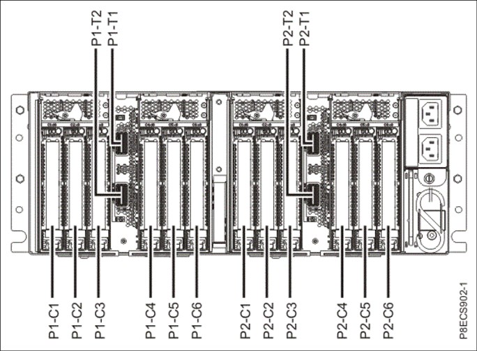
Figure 2-25 Connector locations for the PCIe Gen3 I/O expansion drawer
Figure 2-26 shows typical optical cable connections.

Figure 2-26 Typical optical cable connections
General rules for the PCI Gen3 I/O expansion drawer configuration
The PCIe3 Optical Cable Adapter for PCIe3 Expansion Drawer (#EJ05) is supported in slots P1-C4 and P1-C9 for the Power S922 system. This is a double-wide adapter that requires two adjacent slots. If #EJ05 is installed in this slot, the external SAS port is not allowed in the system.
The PCIe3 cable adapter for the PCIe3 EMX0 expansion drawer (#EJ08) is supported in P1-C9 for the Power S914 and Power S924 single processor systems. It is supported in P1-C9, P1-C3, and P1-C4 in the Power S924 double processor systems.
Table 2-49 shows PCIe adapter slot priorities and maximum adapters that are supported in the Power S922, Power S914, and Power S924 systems.
Table 2-49 PCIe adapter slot priorities and maximum adapters that are supported
|
System
|
Feature code
|
Slot priorities
|
Maximum number of adapters supported
|
|
Power S922
(1 processor)
|
#EJ05
|
9
|
1
|
|
Power S922
(2 processor)
|
#EJ05
|
9/10, 3/4
|
2
|
|
Power S914
|
#EJ08
|
9
|
1
|
|
Power S924
(1 processor)
|
#EJ08
|
9
|
1
|
|
Power S924
(2 processor)
|
#EJ08
|
9, 3, 4
|
3
|
2.7.3 PCIe Gen3 I/O expansion drawer system power control network cabling
There is no system power control network (SPCN) that is used to control and monitor the status of power and cooling within the I/O drawer. SPCN capabilities are integrated into the optical cables.
2.8 External disk subsystems
This section describes the following external disk subsystems that can be attached to the Power S922, Power S914, and Power S924 servers:
•EXP24SX SAS Storage Enclosure (#ESLS) and EXP12SX SAS Storage Enclosure (#ESLL)
•IBM Storage
2.8.1 EXP24SX SAS Storage Enclosure and EXP12SX SAS Storage Enclosure
The EXP24SX is a storage expansion enclosure with 24 2.5-inch SFF SAS bays. It supports up to 24 hot-swap HDDs or SSDs in only 2 EIA of space in a 19-inch rack. The EXP24SX SFF bays use SFF gen2 (SFF-2) carriers/ trays that are identical to the carrier/trays in the previous EXP24S drawer. With AIX and Linux, or VIOS, the EXP24SX can be ordered with four sets of six bays (mode 4), two sets of 12 bays (mode 2), or one set of 24 bays (mode 1). With IBM i, one set of 24 bays (mode 1) is supported.
There can be no mixing of HDDs and SSDs in the same mode 1 drawer. HDDs and SSDs can be mixed in a mode 2 or mode 4 drawer, but they cannot be mixed within a logical split of the drawer. For example, in a mode 2 drawer with two sets of 12 bays, one set can hold SSDs and one set can hold HDDs, but you cannot mix SSDs and HDDs in the same set of 12 bays.
The EXP12SX is a storage expansion enclosure with twelve 3.5-inch large form factor (LFF) SAS bays. It supports up to 12 hot-swap HDDs in only 2 EIA of space in a 19-inch rack. The EXP12SX SFF bays use LFF gen1 (LFF-1) carriers/trays. 4-KB sector drives (4096 or 4224) are supported. With AIX and Linux, and VIOS, the EXP12SX can be ordered with four sets of three bays (mode 4), two sets of six bays (mode 2), or one set of 12 bays (mode 1). Only 4-KB sector drives are supported in the EXP12SX drawer.
Four mini-SAS HD ports on the EXP24SX or EXP12SX are attached to PCIe Gen3 SAS adapters or attached to an integrated SAS controller in the Power S922, S914, or S924 systems. The following PCIe3 SAS adapters support the EXP24SX and EXP 12SX:
•PCIe3 RAID SAS Adapter Quad-port 6 Gb x8 (#EJ0J, #EJ0M, #EL3B, or #EL59)
•PCIe3 12 GB Cache RAID Plus SAS Adapter Quad-port 6 Gb x8 (#EJ14)
Earlier generation PCIe2 or PCIe1 SAS adapters are not supported by the EXP24SX.
The attachment between the EXP24SX or EXP12SX and the PCIe3 SAS adapters or integrated SAS controllers is through SAS YO12 or X12 cables. All ends of the YO12 and X12 cables have mini-SAS HD narrow connectors. The cable options are:
•X12 cable: 3-meter copper (#ECDJ)
•YO12 cables: 1.5-meter copper (#ECDT) or 3-meter copper (#ECDU)
•3M 100 GbE Optical Cable QSFP28 (AOC) (#EB5R)
•5M 100 GbE Optical Cable QSFP28 (AOC) (#EB5S)
•10M 100 GbE Optical Cable QSFP28 (AOC) (#EB5T)
•15M 100 GbE Optical Cable QSFP28 (AOC) (#EB5U)
•20M 100 GbE Optical Cable QSFP28 (AOC) (#EB5V)
•30M 100 GbE Optical Cable QSFP28 (AOC) (#EB5W)
•50M 100 GbE Optical Cable QSFP28 (AOC) (#EB5X)
•100M 100 GbE Optical Cable QSFP28 (AOC) (#EB5Y)
There are six SAS connectors at the rear of the EXP24SX and EXP12SX to which SAS adapters or controllers are attached. They are labeled T1, T2, and T3; there are two T1, two T2, and two T3 connectors.
•In mode 1, two or four of the six ports are used. Two T2 ports are used for a single SAS adapter, and two T2 and two T3 ports are used with a paired set of two adapters or a dual adapters configuration.
•In mode 2 or mode 4, four ports are used, two T2s and two T3s, to access all SAS bays.
Figure 2-27 shows connector locations for the EXP24SX and EXP12SX storage enclosures.

Figure 2-27 Connector locations for the EXP24SX and EXP12SX storage enclosures
For more information about SAS cabling, see the “Connecting an ESLL or ESLS storage enclosure to your system” topic in IBM Knowledge Center.
The EXP24SX and EXP12SX drawers have many high-reliability design points:
•SAS bays that support hot-swap.
•Redundant and hot-plug power and fan assemblies.
•Dual power cords.
•Redundant and hot-plug ESMs.
•Redundant data paths to all drives.
•LED indicators on drives, bays, ESMs, and power supplies that support problem identification.
•Through the SAS adapters/controllers, drives that can be protected with RAID and mirroring and hot-spare capability.
2.8.2 IBM Storage
The IBM Storage Systems products and offerings provide compelling storage solutions with superior value for all levels of business, from entry-level to high-end storage systems. For more information about the various offerings, see Data Storage Solutions.
The following sections highlight a few of the offerings.
IBM Flash Storage
The next generation of IBM Flash Storage delivers the extreme performance and efficiency you need to succeed, with a new pay-as-you-go option to reduce your costs and scale-on-demand. For more information, see Flash Storage and All Flash Arrays.
IBM DS8880 hybrid storage
IBM DS8880 Hybrid Storage is a family of storage systems that includes the IBM DS8886 storage system for high-performance functionality in a dense, expandable package, and the IBM DS8884 storage system to provide advanced functionality for consolidated systems or multiple platforms in a space-saving design. IBM DS8880 systems combine resiliency and intelligent flash performance to deliver microsecond application response times and more than six-nines availability. For more information, see IBM DS8880 hybrid storage - Overview.
IBM XIV Storage System
IBM XIV® Gen3 is a high-end, grid-scale storage system that excels in tuning-free consistent performance, extreme ease of use, and exceptional data economics, including inline, field-proven IBM Real-time Compression™. IBM XIV is ideal for hybrid cloud, offering predictable service levels for dynamic workloads, simplified scale management, including in multi-tenant environments, flexible consumption models, and robust cloud automation and orchestration through OpenStack, the RESTful API, and VMware. It offers security and data protection through hot encryption, advanced mirroring and self-healing, and investment protection with perpetual licensing. For more information, see IBM XIV Storage System - Overview.
IBM Storwize V7000
IBM Storwize® V7000 is an enterprise-class storage solution that offers the advantages of IBM Spectrum™ Virtualize software. It can help you lower capital and operational storage costs with heterogeneous data services while optimizing performance with flash storage. IBM Storwize V7000 enables you to take advantage of hybrid cloud technology without replacing your current storage. For more information, see IBM Storwize V7000 - Overview.
IBM Storwize V5000
IBM Storwize V5000 is a flexible storage solution that offers extraordinary scalability from the smallest to the largest system without disruption. Built with IBM Spectrum Virtualize™ software, it can help you lower capital and operational storage costs with heterogeneous data services. IBM Storwize V5000 is an easily customizable and upgradeable solution for better investment protection, improved performance, and enhanced efficiency. For more information, see IBM Storwize V5000 - Overview.
2.9 Operating system support
The Power S922, Power S914, and Power S924 servers support the following operating systems:
•AIX
•IBM i (by using the VIOS)
•Linux
In addition, the VIOS can be installed in special partitions that provide support to other partitions running AIX, IBM i, or Linux operating systems for using features such as virtualized I/O devices, PowerVM Live Partition Mobility (LPM), or PowerVM Active Memory Sharing.
For more information about the software that is available on IBM Power Systems, see
IBM Power Systems Software.
IBM Power Systems Software.
2.9.1 AIX operating system
The following sections describe the various levels of AIX operating system support.
IBM periodically releases maintenance packages (service packs or technology levels) for the AIX operating system. For more information about these packages, downloading, and obtaining the CD-ROM, see Fix Central.
The Fix Central website also provides information about how to obtain the fixes that are included on CD-ROM.
The Service Update Management Assistant (SUMA), which can help you automate the task of checking and downloading operating system downloads, is part of the base operating system. For more information about the suma command, see IBM Knowledge Center.
The following minimum levels of AIX support the Power S922, Power S914, and Power S924 servers:
•If you are installing the AIX operating system LPAR with any I/O configuration:
– AIX Version 7.2 with the 7200-02 Technology Level and Service Pack 7200-02-02-1810, or later
– AIX Version 7.1 with the 7100-05 Technology Level and Service Pack 7100-05-02-1810, or later
– AIX Version 6.1 with the 6100-09 Technology Level and Service Pack 6100-09-11-1810, or later
– AIX Version 7.2 with the 7200-01 Technology Level and Service Pack 7200-01-04-1806, or later
– AIX Version 7.2 with the 7200-00 Technology Level and Service Pack 7200-00-06-1806, or later
– AIX Version 7.1 with the 7100-04 Technology Level and Service pack 7100-04-06-1806, or later
•If you are installing the AIX operating system Virtual I/O only LPAR:
– AIX Version 7.2 with the 7200-02 Technology Level and Service Pack 7200-02-01-1732, or later
– AIX Version 7.2 with the 7200-01 Technology Level and Service Pack 7200-01-01-1642, or later
– AIX Version 7.2 with the 7200-00 Technology Level and Service Pack 7200-00-01-1543, or later
– AIX Version 7.1 with the 7100-05 Technology Level and Service Pack 7100-05-01-1731, or later
– AIX Version 7.1 with the 7100-04 Technology Level and Service Pack 7100-04-01-1543, or later
– AIX Version 6.1 with the 6100-09 Technology Level and Service Pack 6100-09-06-1543, or later (AIX 6.1 service extension required.)
2.9.2 IBM i
IBM i is supported on the Power S922, Power S914, and Power S924 servers with the following minimum required levels:
•IBM i 7.3 TR4
•IBM i 7.2 TR8
IBM periodically releases maintenance packages (service packs or technology levels) for the IBM i operating system. For more information about these packages, downloading, and obtaining the CD-ROM, see IBM Fix Central.
For compatibility information for hardware features and the corresponding AIX and IBM i Technology Levels, see IBM Prerequisites.
2.9.3 Linux operating system
Linux is an open source, cross-platform operating system that runs on numerous platforms from embedded systems to mainframe computers. It provides an UNIX -like implementation across many computer architectures.
The supported versions of Linux on the Power S922, Power S914, and Power S924 servers are as follows:
•If you are installing the Linux operating system LPAR:
– Red Hat Enterprise Linux 7 for Power LE Version 7.4, or later (POWER8 mode).
– SUSE Linux Enterprise Server 12 Service Pack 3, or later.
– Ubuntu Server 16.04.4, or later (POWER8 mode).
•If you are installing the Linux operating systems LPAR in non-production SAP implementations:
– SUSE Linux Enterprise Server 12 Service Pack 3, or later.
– SUSE Linux Enterprise Server for SAP with SUSE Linux Enterprise Server 12 Service Pack 3, or later.
– Red Hat Enterprise Linux 7 for Power LE, version 7.4, or later (POWER8 mode).
– Red Hat Enterprise Linux for SAP with Red Hat Enterprise Linux 7 for Power LE version 7.4, or later (POWER8 mode). Linux supports almost all of the Power Systems I/O, and the configurator verifies support on order.
Service and productivity tools
Service and productivity tools are available in a YUM repository that you can use to download, and then install, all the recommended packages for your Red Hat, SUSE Linux, or Fedora distribution. The packages are available from Service and productivity tools for Linux on Power servers.
To learn about developing on the IBM Power Architecture®, find packages, get access to cloud resources, and discover tools and technologies, see Linux on IBM Power Systems Developer Portal.
The IBM Advance Toolchain for Linux on Power is a set of open source compilers, runtime libraries, and development tools that users can use to take leading-edge advantage of IBM POWER hardware features on Linux. For more information, see Advanced Toolchain for Linux on Power.
For more information about SUSE Linux Enterprise Server, see SUSE Linux Enterprise Server.
For more information about Red Hat Enterprise Linux, see Red Hat Enterprise Linux.
2.9.4 Virtual I/O Server
The minimum required level of VIOS for the Power S922, Power S914, and Power S924 servers is VIOS 2.2.6.21.
2.10 POWER9 reliability, availability, and serviceability capabilities
This section provides information about IBM Power Systems reliability, availability, and serviceability (RAS) design and features.
The elements of RAS can be described as follows:
Reliability Indicates how infrequently a defect or fault in a server occurs.
Availability Indicates how infrequently the functioning of a system or application is impacted by a fault or defect.
Serviceability Indicates how well faults and their effects are communicated to system managers and how efficiently and nondisruptively the faults are repaired.
Table 2-50 provides a list of the Power Systems RAS capabilities by operating system. The HMC is an optional feature on scale-out Power Systems servers.
Table 2-50 Selected reliability, availability, and serviceability features by operating system
|
RAS feature
|
AIX
|
IBM i
|
Linux
|
|
Processor
|
|||
|
First failure data capture (FFDC) for fault detection/error isolation
|
X
|
X
|
X
|
|
Dynamic Processor Deallocation
|
X
|
X
|
X
|
|
I/O subsystem
|
|||
|
PCI Express bus enhanced error detection
|
X
|
X
|
X
|
|
PCI Express bus enhanced error recovery
|
X
|
X
|
X
|
|
PCI Express card hot-swap
|
X
|
X
|
X
|
|
Memory availability
|
|||
|
Memory Page Deallocation
|
X
|
X
|
X
|
|
Special Uncorrectable Error Handling
|
X
|
X
|
X
|
|
Fault detection and isolation
|
|||
|
Storage Protection Keys
|
X
|
Not used by OS
|
Not used by OS
|
|
Error log analysis
|
X
|
X
|
X
|
|
Serviceability
|
|||
|
Boot-time progress indicators
|
X
|
X
|
X
|
|
Firmware error codes
|
X
|
X
|
X
|
|
Operating system error codes
|
X
|
X
|
X
|
|
Inventory collection
|
X
|
X
|
X
|
|
Environmental and power warnings
|
X
|
X
|
X
|
|
Hot-swap DASD / media
|
X
|
X
|
X
|
|
Dual disk controllers / Split backplane
|
X
|
X
|
X
|
|
EED collection
|
X
|
X
|
X
|
|
SP/OS “Call Home” on non-HMC configurations
|
X
|
X
|
X
|
|
IO adapter/device stand-alone diagnostic tests with PowerVM
|
X
|
X
|
X
|
|
SP mutual surveillance with IBM POWER Hypervisor™
|
X
|
X
|
X
|
|
Dynamic firmware update with HMC
|
X
|
X
|
X
|
|
Service Agent Call Home Application
|
X
|
X
|
X
|
|
Service Indicator LED support
|
X
|
X
|
X
|
|
System dump for memory, POWER Hypervisor, and SP
|
X
|
X
|
X
|
|
IBM Knowledge Center / IBM Systems Support Site service publications
|
X
|
X
|
X
|
|
System Service/Support Education
|
X
|
X
|
X
|
|
Operating system error reporting to HMC Service Focal Point (SFP) application
|
X
|
X
|
X
|
|
RMC secure error transmission subsystem
|
X
|
X
|
X
|
|
Healthcheck scheduled operations with HMC
|
X
|
X
|
X
|
|
Operator panel (real or virtual [HMC])
|
X
|
X
|
X
|
|
Concurrent Op Panel Display Maintenance
|
X
|
X
|
X
|
|
Redundant HMCs
|
X
|
X
|
X
|
|
High availability clustering support
|
X
|
X
|
X
|
|
Repair and Verify Guided Maintenance with HMC
|
X
|
X
|
X
|
|
PowerVM Live Partition / Live Application Mobility With PowerVM Enterprise Edition
|
X
|
X
|
X
|
|
EPOW
|
|||
|
EPOW errors handling
|
X
|
X
|
X
|
2.11 Manageability
Several functions and tools help with manageability so that you can efficiently and effectively manage your system.
2.11.1 Service user interfaces
The service user interface enables support personnel or the client to communicate with the service support applications in a server by using a console, interface, or terminal. Delivering a clear, concise view of available service applications, the service interface enables the support team to manage system resources and service information in an efficient and effective way. Applications that are available through the service interface are carefully configured and placed to give service providers access to important service functions.
Various service interfaces are used, depending on the state of the system and its operating environment. Here are the primary service interfaces:
•Light Path, which provides indicator lights to help a service technical find a component in need of service.
•Service processor.
•ASMI.
•Operator panel.
•An operating system service menu, which obtains error codes directly from the hardware.
•Service Focal Point (SFP) on the HMC.
Service processor
The service processor is a controller that is running its own operating system. It is a component of the service interface card.
The service processor operating system has specific programs and device drivers for the service processor hardware. The host interface is a processor support interface that is connected to the POWER processor. The service processor is always working, regardless of the main system unit’s state. The system unit can be in the following states:
•Standby (power off)
•Operating, ready to start partitions
•Operating with running logical partitions (LPARs)
The service processor is used to monitor and manage the system hardware resources and devices. The service processor checks the system for errors, ensuring that the connection to the management console for manageability purposes is functioning, and accepting ASMI Secure Sockets Layer (SSL) network connections. The service processor can view and manage the machine-wide settings by using the ASMI, which enables complete system and partition management from the HMC.
|
Analyzing a system that does not start: The flexible service processor (FSP) can analyze a system that does not start. Reference codes and detailed data are available in the ASMI and are transferred to the HMC.
|
The service processor uses two Ethernet ports that run at 1-Gbps speed. Consider the following information:
•Both Ethernet ports are visible only to the service processor and can be used to attach the server to an HMC or to access the ASMI. The ASMI options can be accessed through an HTTP server that is integrated into the service processor operating environment.
•Both Ethernet ports support only auto-negotiation. Customer-selectable media speed and duplex settings are not available.
•Both Ethernet ports have a default IP address, as follows:
– Service processor eth0 (HMC1 port) is configured as 169.254.2.147.
– Service processor eth1 (HMC2 port) is configured as 169.254.3.147.
– DHCP using the HMC for the HMC management networks is also possible.
The following functions are available through the service processor:
•Call Home
•ASMI
•Error information (error code, part number, and location codes) menu
•View of guarded components
•Limited repair procedures
•Generate dump
•LED Management menu
•Remote view of ASMI menus
•Firmware update through a USB key
Advanced System Management Interface
ASMI is the interface to the service processor that enables you to manage the operation of the server, such as auto-power restart, and to view information about the server, such as the error log and Vital Product Data (VPD). Various repair procedures require connection to the ASMI.
The ASMI is accessible through the management console. It is also accessible by using a web browser on a system that is connected directly to the service processor (in this case, either a standard Ethernet cable or a crossed cable) or through an Ethernet network. ASMI can also be accessed from an ASCII terminal, but this is available only while the system is in the platform powered-off mode.
Figure 2-28 shows a method of opening ASMI on a particular server by using the HMC GUI.

Figure 2-28 Starting the Advanced System Management Interface through the HMC GUI
You are prompted for confirmation about which FSP to use, and then a login window opens, as shown in Figure 2-29.

Figure 2-29 The ASMI login window
After you are logged in (the default credentials are admin/admin), you see the menu that is shown in Figure 2-30.

Figure 2-30 An ASMI window
|
Tip: If you click Expand all menus, as shown in the red ring, you can then use the search function (Ctrl+f) in your browser to find quickly menu items.
|
Use the ASMI to change the service processor IP addresses or to apply certain security policies and prevent access from unwanted IP addresses or ranges.
You might be able to use the service processor’s default settings. In that case, accessing the ASMI is not necessary. To access ASMI, use one of the following methods:
•Use a management console.
If configured to do so, the management console connects directly to the ASMI for a selected system from this task.
To connect to the ASMI from a management console, complete the following steps:
a. Open Systems Management from the navigation pane.
b. From the work window, select one of the managed systems.
c. From the System Management tasks list, click Operations → Launch Advanced System Management (ASMI).
•Use a web browser.
At the time of writing, the supported web browsers are Microsoft Internet Explorer (Version 10.0.9200.16439), Mozilla Firefox ESR (Version 24), and Chrome (Version 30). Later versions of these browsers might work, but are not officially supported. The JavaScript language and cookies must be enabled, and TLS 1.2 might need to be enabled.
The web interface is available during all phases of system operation, including the initial program load (IPL) and run time. However, several of the menu options in the web interface are unavailable during IPL or run time to prevent usage or ownership conflicts if the system resources are in use during that phase. The ASMI provides an SSL web connection to the service processor. To establish an SSL connection, open your browser go to the following address:
https://<ip_address_of_service_processor>
|
Note: To make the connection through Internet Explorer, click Tools Internet Options. Clear the Use TLS 1.0 check box, and click OK.
|
•Use an ASCII terminal.
The ASMI on an ASCII terminal supports a subset of the functions that are provided by the web interface and is available only when the system is in the platform powered-off mode. The ASMI on an ASCII console is not available during several phases of system operation, such as the IPL and run time.
•Command-line start of the ASMI
Either on the HMC itself or when properly configured on a remote system, it is possible to start ASMI web interface from the HMC command line. Open a terminal window on the HMC or access the HMC with a terminal emulation and run the following command:
asmmenu --ip <ip address>
On the HMC itself, a browser window opens automatically with the ASMI window and, when configured properly, a browser window opens on a remote system when issued from there.
The operator panel
The service processor provides an interface to the operator panel, which is used to display system status and diagnostic information.
The operator panel is formed of two parts: One is always installed, and the second might be optional.
The part that is always installed provides LEDs and sensors:
•Power LED:
– Color: Green.
– Off: Enclosure is off (AC cord is not connected).
– On Solid: Enclosure is powered on.
– On Blink: Enclosure is in the standby-power state.
•Enclosure Identify LED. Color: Blue.
•Enclosure Identify LED:
– Color: Blue.
– Off: Normal.
– On Solid: Identify State.
•System Fault LED:
– Color: Amber.
– Off: Normal.
– On Solid: Check Error Log.
•System Roll-up LED:
– Color: Amber.
– Off: Normal.
– On Solid: Fault.
•Power Button.
•System Reset Switch.
•Two Thermal Sensors.
•One Pressure/Altitude Sensor.
The LCD operator panel is optional in some systems, but there must be at least one in a server in a rack containing any IBM Power S914, Power S922, or Power S924 server. The panel can be accessed by using the switches on the front panel.
Here are several of the operator panel features:
•A 2 x 16 character LCD display
•Increment, decrement, and “enter” buttons
The following functions are available through the operator panel:
•Error information
•Generate dump
•View machine type, model, and serial number
•Limited set of repair functions
The System Management Services (SMS) error log is accessible through the SMS menus. This error log contains errors that are found by partition firmware when the system or partition is starting.
The service processor’s error log can be accessed on the ASMI menus.
You can also access the system diagnostics from a Network Installation Management (NIM) server.
IBM i and its associated machine code provide dedicated service tools (DSTs) as part of the IBM i licensed machine code (Licensed Internal Code) and System Service Tools (SSTs) as part of IBM i. DSTs can be run in dedicated mode (no operating system is loaded). DSTs and diagnostic tests are a superset of those available under SSTs.
The IBM i End Subsystem (ENDSBS *ALL) command can shut down all IBM and customer applications subsystems except for the controlling subsystem QTCL. The Power Down System (PWRDWNSYS) command can be set to power down the IBM i partition and restart the partition in DST mode.
You can start SSTs during normal operations, which keep all applications running, by using the IBM i Start Service Tools (STRSST) command (when signed on to IBM i with the appropriately secured user ID).
With DSTs and SSTs, you can look at various logs, run various diagnostic tests, or take several kinds of system memory dumps or other options.
Depending on the operating system, the following service-level functions are what you typically see when you use the operating system service menus:
•Product activity log
•Trace Licensed Internal Code
•Work with communications trace
•Display/Alter/Dump
•Licensed Internal Code log
•Main storage memory dump manager
•Hardware service manager
•Call Home/Customer Notification
•Error information menu
•LED management menu
•Concurrent/Non-concurrent maintenance (within scope of the OS)
•Managing firmware levels:
– Server
– Adapter
•Remote support (access varies by OS)
Service Focal Point on the Hardware Management Console
Service strategies become more complicated in a partitioned environment. The Manage Serviceable Events task in the management console can help streamline this process.
Each LPAR reports errors that it detects and forwards the event to the SFP application that is running on the management console, without determining whether other LPARs also detect and report the errors. For example, if one LPAR reports an error for a shared resource, such as a managed system power supply, other active LPARs might report the same error.
By using the Manage Serviceable Events task in the management console, you can avoid long lists of repetitive Call Home information by recognizing that they are repeated errors and consolidating them into one error.
In addition, you can use the Manage Serviceable Events task to initiate service functions on systems and LPARs, including the exchanging of parts, configuring connectivity, and managing memory dumps.
2.11.2 IBM Power Systems Firmware maintenance
The IBM Power Systems Client-Managed Microcode is a methodology that enables you to manage and install microcode updates on Power Systems servers and their associated I/O adapters.
Firmware entitlement
With the new HMC Version V8R8.1.0.0 and Power Systems servers, the firmware installations are restricted to entitled servers. The customer must be registered with IBM and entitled by a service contract. During the initial machine warranty period, the access key is installed in the machine by manufacturing. The key is valid for the regular warranty period plus some extra time. The Power Systems Firmware is relocated from the public repository to the access control repository. The I/O firmware remains on the public repository, but the server must be entitled for installation. When the lslic command is run to display the firmware levels, a new value, update_access_key_exp_date, is added. The HMC GUI and the ASMI menu show the Update access key expiration date.
When the system is no longer entitled, the firmware updates fail. Some new System Reference Code (SRC) packages are available:
•E302FA06: Acquisition entitlement check failed
•E302FA08: Installation entitlement check failed
Any firmware release that was made available during the entitled time frame can still be installed. For example, if the entitlement period ends on 31 December 2014, and a new firmware release is release before the end of that entitlement period, then it can still be installed. If that firmware is downloaded after 31 December 2014, but it was made available before the end of the entitlement period, it still can be installed. Any newer release requires a new update access key.
|
Note: The update access key expiration date requires a valid entitlement of the system to perform firmware updates.
|
You can find an update access key at IBM CoD Home.
For more information, go to IBM Entitled Software Support.
Firmware updates
System firmware is delivered as a release level or a service pack. Release levels support the general availability (GA) of new functions or features, and new machine types or models. Upgrading to a higher release level is disruptive to customer operations. IBM intends to introduce no more than two new release levels per year. These release levels will be supported by service packs. Service packs are intended to contain only firmware fixes and not introduce new functions. A service pack is an update to an existing release level.
If the system is managed by a management console, you use the management console for firmware updates. By using the management console, you can take advantage of the CFM option when concurrent service packs are available. CFM is the IBM Power Systems Firmware updates that can be partially or wholly concurrent or nondisruptive. With the introduction of CFM, IBM is increasing its clients’ opportunity to stay on a given release level for longer periods. Clients that want maximum stability can defer until there is a compelling reason to upgrade, such as the following reasons:
•A release level is approaching its end of service date (that is, it has been available for about a year, and soon service will not be supported).
•Move a system to a more standardized release level when there are multiple systems in an environment with similar hardware.
•A new release has a new function that is needed in the environment.
•A scheduled maintenance action causes a platform restart, which provides an opportunity to also upgrade to a new firmware release.
The updating and upgrading of system firmware depends on several factors, such as whether the system is stand-alone or managed by a management console, the firmware that is installed, and what operating systems are running on the system. These scenarios and the associated installation instructions are comprehensively outlined in the firmware section of Fix Central.
You might also want to review the preferred practice white papers that are found at
Service and support best practices for Power Systems.
Service and support best practices for Power Systems.
Firmware update steps
The system firmware consists of service processor microcode, Open Firmware microcode, and SPCN microcode.
The firmware and microcode can be downloaded and installed either from an HMC, from a running partition, or from USB port number 1 on the rear, if that system is not managed by an HMC.
Power Systems Firmware has a permanent firmware boot side (A side) and a temporary firmware boot side (B side). New levels of firmware must be installed first on the temporary side to test the update’s compatibility with existing applications. When the new level of firmware is approved, it can be copied to the permanent side.
For access to the initial websites that address this capability, see Support for IBM Systems. For Power Systems, select the Power link.
Although the content under the Popular links section can change, click the Firmware and HMC updates link to go to the resources for keeping your system’s firmware current.
If there is an HMC to manage the server, the HMC interface can be used to view the levels of server firmware and power subsystem firmware that are installed and that are available to download and install.
Each IBM Power Systems server has the following levels of server firmware and power subsystem firmware:
•Installed level
This level of server firmware or power subsystem firmware is installed and will be installed into memory after the managed system is powered off and then powered on. It is installed on the temporary side of system firmware.
•Activated level
This level of server firmware or power subsystem firmware is active and running in memory.
•Accepted level
This level is the backup level of the server or power subsystem firmware. You can return to this level of server or power subsystem firmware if you decide to remove the installed level. It is installed on the permanent side of system firmware.
Figure 2-31 shows the different levels in the HMC.

Figure 2-31 Firmware levels
IBM provides the CFM function on selected Power Systems servers. This function supports applying nondisruptive system firmware service packs to the system concurrently (without requiring a restart operation to activate changes). For systems that are not managed by an HMC, the installation of system firmware is always disruptive.
The concurrent levels of system firmware can, on occasion, contain fixes that are known as deferred. These deferred fixes can be installed concurrently but are not activated until the next IPL. Deferred fixes, if any, are identified in the Firmware Update Descriptions table of the firmware document. For deferred fixes within a service pack, only the fixes in the service pack that cannot be concurrently activated are deferred.
Table 2-51 shows the file-naming convention for system firmware.
Table 2-51 Firmware naming convention
|
PPNNSSS_FFF_DDD
|
|||
|
PP
|
Package identifier
|
01
|
-
|
|
NN
|
Platform and class
|
VL
|
Low end
|
|
SSS
|
Release indicator
|
||
|
FFF
|
Current fix pack
|
||
|
DDD
|
Last disruptive fix pack
|
||
The following example uses the convention:
01VL910,73,73 = POWER9 Entry Systems Firmware for 9009-41A, 9009-22A, and 9009-42A
An installation is disruptive if the following statements are true:
•The release levels (SSS) of the currently installed and the new firmware differ.
•The service pack level (FFF) and the last disruptive service pack level (DDD) are equal in the new firmware.
Otherwise, an installation is concurrent if the service pack level (FFF) of the new firmware is higher than the service pack level that is installed on the system and the conditions for disruptive installation are not met.
2.11.3 Concurrent firmware maintenance improvements
Since POWER6, firmware service packs (updates) are concurrently applied and take effect immediately. Occasionally, a service pack is shipped where most of the features can be concurrently applied, but because changes to some server functions (for example, changing initialization values for chip controls) cannot occur during operation, a patch in this area required a system restart for activation.
With the Power-On Reset Engine (PORE), the firmware can now dynamically power off processor components, change the registers, and reinitialize while the system is running, without discernible impact to any applications running on a processor, which potentially allows concurrent firmware changes in POWER9, which in earlier designs required a restart to take effect.
Activating new firmware functions requires the installation of a firmware release level (upgrades). This process is disruptive to server operations, and requires a scheduled outage and full server restart.
2.11.4 Electronic Services and Electronic Service Agent
IBM transformed its delivery of hardware and software support services to help you achieve higher system availability. Electronic Services is a web-enabled solution that offers an exclusive, no additional charge enhancement to the service and support that is available for IBM servers. These services provide the opportunity for greater system availability with faster problem resolution and preemptive monitoring. The Electronic Services solution consists of two separate, but complementary, elements:
Electronic Services news page
The Electronic Services news page is a single internet entry point that replaces the multiple entry points that traditionally are used to access IBM internet services and support. With the news page, you can gain easier access to IBM resources for assistance in resolving technical problems.
Electronic Service Agent
The Electronic Service Agent (ESA) is software that is on your server. It monitors events and transmits system inventory information to IBM on a periodic, client-defined timetable. The ESA automatically reports hardware problems to IBM.
Early knowledge about potential problems enables IBM to deliver proactive service that can result in higher system availability and performance. In addition, information that is collected through the ESA is made available to IBM Support Services Representatives (IBM SSRs) when they help answer your questions or diagnose problems. Installation and use of ESA for problem reporting enables IBM to provide better support and service for your IBM server.
To learn how Electronic Services can work for you, see IBM Electronic Services (an IBM ID is required).
Here are some of the benefits of Electronic Services:
•Increased uptime
The ESA tool enhances the warranty or maintenance agreement by providing faster hardware error reporting and uploading system information to IBM Support, which can translate to less time that is wasted monitoring the symptoms, diagnosing the error, and manually calling IBM Support to open a problem record.
Its 24x7 monitoring and reporting mean no more dependence on human intervention or off-hours customer personnel when errors are encountered in the middle of the night.
•Security
The ESA tool is designed to be secure in monitoring, reporting, and storing the data at IBM. The ESA tool securely transmits either through the internet (HTTPS or VPN) or modem, and can be configured to communicate securely through gateways to provide customers a single point of exit from their site.
Communication is one way. Activating ESA does not enable IBM to call into a customer's system. System inventory information is stored in a secure database, which is protected behind IBM firewalls. It is viewable only by the customer and IBM. The customer's business applications or business data is never transmitted to IBM.
•More accurate reporting
Because system information and error logs are automatically uploaded to the IBM Support center with the service request, customers are not required to find and send system information, decreasing the risk of misreported or misdiagnosed errors.
When inside IBM, problem error data is run through a data knowledge management system, and knowledge articles are appended to the problem record.
•Customized support
By using the IBM ID that you enter during activation, you can view system and support information by selecting My Systems at Electronic Support.
My Systems provides valuable reports of installed hardware and software by using information that is collected from the systems by ESA. Reports are available for any system that is associated with the customers IBM ID. Premium Search combines the function of search and the value of ESA information, providing advanced search of the technical support knowledge base. Using Premium Search and the ESA information that was collected from your system, your clients can see search results that apply specifically to their systems.
For more information about how to use the power of IBM Electronic Services, contact your IBM SSR, or see Electronic Support.
Service Event Manager
The Service Event Manager (SEM) enables the user to decide which of the Serviceable Events are called home by the ESA. It is possible to lock certain events. Some customers might not allow data to be transferred outside their company. After the SEM is enabled, the analysis of the possible problems might take longer.
•The SEM can be enabled by running the following command:
chhmc -c sem -s enable
•You can disable SEM mode and specify what state in which to leave the Call Home feature by running the following commands:
chhmc -c sem -s disable --callhome disable
chhmc -c sem -s disable --callhome enable
The easiest way to set up the ESA is by using the wizard in the HMC GUI, which is shown in Figure 2-32.

Figure 2-32 Accessing the Electronic Service Agent setup wizard
The wizard guides the user through the necessary steps, including entering details about the location of the system, the contact details, and other details. The user can select which HMC or HMCs should be used, as shown in Figure 2-33.

Figure 2-33 Managing which HMCs are used for Call Home
If you select a server, you can easily open the SEM, as shown in Figure 2-34.

Figure 2-34 Opening the Serviceable Events Manager for a server
The user can then navigate the SEM menus to see the events for this server, as shown in Figure 2-35.

Figure 2-35 Serviceable events for this server
..................Content has been hidden....................
You can't read the all page of ebook, please click here login for view all page.