

IBM Z and DS8880 performance
This chapter describes the IBM Z and DS8880 synergy features from a performance perspective and how these features contribute to enhanced resiliency of an overall mainframe storage infrastructure.
This chapter includes the following topics:
5.1 Parallel access volume, HyperPAV, and SuperPAV
Parallel access volume (PAV) is an optional licensed function of the DS8000 storage system for the z/OS and z/VM operating systems. The function helps the IBM Z servers that are running applications to share concurrently logical volumes.
The ability to handle multiple I/O requests to the same volume nearly eliminates I/O Supervisor queue (IOSQ) delay time, which is one of the major components that affect z/OS response time. Traditionally, access to highly active volumes involved manual tuning, splitting data across multiple volumes, and more. With PAV and the Workload Manager (WLM), you can almost forget about manual performance tuning. WLM also manages PAVs across all the members of a sysplex.
Traditional z/OS behavior without PAV
Traditional storage disk systems (which allow for only one channel program to be active to a volume at a time to ensure that data that is accessed by one channel program) cannot be altered by the activities of another channel program.
The traditional z/OS behavior without PAV, where subsequent simultaneous I/Os to volume 100 are queued while volume 100 is still busy with a previous I/O, is shown in Figure 5-1.

Figure 5-1 Traditional z/OS behavior
From a performance perspective, sending more than one I/O at a time to the storage system did not make sense because the hardware processes only one I/O at a time. With this information, the z/OS systems did not try to issue another I/O to a volume (which, in z/OS, is represented by a unit control block (UCB)) while an I/O was active for that volume, as indicated by a UCB busy flag.
Not only did the z/OS systems process only one I/O at a time, but the storage systems accepted only one I/O at a time from different system images to a shared volume.
Parallel I/O capability z/OS behavior with PAV
The DS8000 storage system runs more than one I/O to a Count Key Data (CKD) volume. By using the alias address and the conventional base address, a z/OS host can use several UCBs for the same logical volume instead of one UCB per logical volume. For example, base address 100 might include alias addresses 1FF and 1FE, which allows for three parallel I/O operations to the same volume, as shown in Figure 5-2.

Figure 5-2 z/OS behavior with PAV
PAV allows parallel I/Os to a volume from one host. The following basic concepts are featured in PAV functions:
•Base device address
The base device address is the conventional unit address of a logical volume. Only one base address is associated with any volume.
•Alias device address
An alias device address is mapped to a base address. I/O operations to an alias run against the associated base address storage space. No physical space is associated with an alias address. You can define more than one alias per base.
Alias addresses must be defined to the DS8000 storage system and to the I/O definition file (IODF). This association is predefined, and you can add aliases nondisruptively. In the static PAV, the relationship between the base and alias addresses is static. Dynamically assigning alias addresses to your base addresses reduces the number of aliases that are required in your system, and are explained next.
For more information about PAV definition and support, see IBM System Storage DS8000: Host Attachment and Interoperability, SG24-8887.
5.1.1 Dynamic PAV tuning with z/OS Workload Manager
Predicting which volumes should include an alias address that is assigned and how many is not always easy. Your software can automatically manage the aliases according to your goals. z/OS can use automatic PAV tuning if you are using the z/OS WLM in goal mode.
The WLM can dynamically tune the assignment of alias addresses. The WLM monitors the device performance and can dynamically reassign alias addresses from one base to another if predefined goals for a workload are not met.
z/OS recognizes the aliases that are initially assigned to a base during the nucleus initialization program phase. If dynamic PAVs are enabled, the WLM can reassign an alias to another base by instructing the Input/Output Supervisor (IOS) to do so when necessary, as shown in Figure 5-3.

Figure 5-3 WLM assignment of alias addresses
z/OS WLM in goal mode tracks system workloads and checks whether workloads are meeting their goals as established by the installation.
WLM also tracks the devices that are used by the workloads, accumulates this information over time, and broadcasts it to the other systems in the same sysplex.
If WLM determines that any workload is not meeting its goal because of IOSQ time, WLM attempts to find an alias device that can be reallocated to help this workload achieve its goal.
As Figure 5-4 shows, WLM checks the IOSQ time of volume 100 and allocates free aliases from volume 110.

Figure 5-4 Dynamic PAVs in a sysplex
5.1.2 HyperPAV
Dynamic PAV requires the WLM to monitor the workload and goals. The process of the WLM detecting an I/O bottleneck and then coordinating the reassignment of alias addresses within the sysplex and the DS8000 storage system can take time. In addition, if the workload is fluctuating or is characterized by burst, the job that caused the overload of one volume might end before the WLM reacts. In these cases, the IOSQ time was not eliminated.
With HyperPAV, an on-demand proactive assignment of aliases is possible, as shown in Figure 5-5.

Figure 5-5 Basic operational characteristics of HyperPAV
With HyperPAV, the WLM is no longer involved in managing alias addresses. For each I/O, an alias address can be automatically picked from a pool of alias addresses within the same logical control unit (LCU).
This capability also allows multiple HyperPAV hosts to use one alias to access different bases, which reduces the number of alias addresses that are required to support a set of bases in an IBM Z environment, with no latency in assigning an alias to a base. This function is also designed to enable applications to achieve better performance than is possible with the original PAV feature alone, whereas the same or fewer operating system resources are used.
Benefits of HyperPAV
HyperPAV offers the following benefits:
•Provides more efficient PAV function.
•Assists with the implementation of larger volumes because I/O rates per device can be scaled up without the need for more PAV alias definitions.
•Can reduce the number of PAV aliases that are needed, which takes fewer from the 64-K device limitation and leaves more devices for capacity use.
•Enables a more dynamic response for changing workloads.
•Simplifies alias management.
HyperPAV alias consideration on an extended address volume
HyperPAV provides a far more agile alias management algorithm because aliases are dynamically bound to a base during the I/O for the z/OS image that issued the I/O. When I/O completes, the alias is returned to the pool in the LCU. It then becomes available to subsequent I/Os.
The general rule is that the number of aliases that are required can be approximated by the peak of the following multiplication: I/O rate that is multiplied by the average response time.
For example, if the peak of the calculation that occurs when the I/O rate is 2000 I/Os per second and the average response time is 4 ms (which is 0.004 sec), the result of the calculation is as follows:
2000 IO/sec x 0.004 sec/IO = 8
This result means that the average number of I/O operations that are running at one time for that LCU during the peak period is eight. Therefore, eight aliases should handle the peak I/O rate for that LCU. However, because this calculation is based on the average during the IBM Resource Measurement Facility™ (RMF™) period, multiply the result by two to accommodate higher peaks within that RMF interval. Therefore, in this case, the advised number of aliases is 16 (2 x 8 = 16).
A more precise approach to know how many PAVs are needed is to look at the RMF I/O Queuing Activity LCU report. The report shows the following values:
•HyperPAV Wait Ratio: Ratio of the number of times an I/O did not start and the total number of I/O requests
•HyperPAV Maximum: Maximum number of concurrently in-use HyperPAV aliases
If a value exists for the HyperPAV Wait Ratio, more PAVs are needed. If no waiting (no value) exists, the maximum is the number of PAVs that is needed. Those values must be monitored and evaluated over time, looking for peaks and comparing values for various logical partitions (LPARs).
Depending on the workload, a large reduction in PAV-alias UCBs with HyperPAV occurs. The combination of HyperPAV and extended address volume (EAV) allows you to reduce the constraint on the 64-K device address limit and in turn increase the amount of addressable storage that is available on z/OS. With multiple subchannel sets (MSSes) on IBM Z, even more flexibility is available in device configuration.
For more information, see the following IBM Redbooks publications:
•For EAV specifications, considerations, and implementation guidance, see IBM System Storage DS8000: Host Attachment and Interoperability, SG24-8887.
•For MSS, see Multiple Subchannel Sets: An Implementation View, REDP-4387.
5.1.3 RMF reporting on PAV
RMF reports the number of exposures for each device in the following reports:
•Monitor/Direct Access Storage Device (DASD) Activity report
•Monitor II and Monitor III Device reports
If the device is a HyperPAV base device, the number is followed by the letter “H” (for example, 5.4H). This value is the average number of HyperPAV volumes (base and alias) in that interval. RMF reports all I/O activity against the base address, not by the individual base and associated aliases. The performance information for the base includes all base and alias I/O activity.
PAV and HyperPAV help minimize the IOSQ Time. You still see IOSQ Time for one of the following reasons:
•More aliases are required to handle the I/O load when compared to the number of aliases that are defined in the LCU.
•A Device Reserve is issued against the volume. A Device Reserve makes the volume unavailable to the next I/O, which causes the next I/O to be queued. This delay is recorded as IOSQ Time.
5.1.4 PAV and HyperPAV in z/VM environments
z/VM provides PAV and HyperPAV support in the following ways:
•As traditionally supported for virtual machine (VM) guests as dedicated guests by using the CP ATTACH command or DEDICATE user directory statement.
•z/VM supports PAV minidisks:
– Base and its aliases can be dedicated to only one guest.
– Base must be dedicated first, and then all required aliases devices.
PAV in a z/VM environment provides linkable minidisks for guests that use PAV (that is, z/OS and Linux), as shown in Figure 5-6.

Figure 5-6 z/VM support of PAV minidisk
Base minidisks are defined by using the existing MDISK or LINK user directory statements. Aliases are defined with the PAVALIAS parameter of the DASDOPT and MINIOPT user directory statements or with the CP DEFINE PAVALIAS command. z/VM also provides workload balancing for guests that do not use PAV (like Conversational Monitor System (CMS)). Real I/O dispatcher queues minidisk I/O across system attached aliases.
To the z/VM environments, PAV provides the benefit of a greater I/O performance (throughput) by reducing I/O queuing.
Starting with z/VM V5.4, z/VM supports HyperPAV for dedicated DASD and minidisks.
For more information about PAV and z/VM, see IBM System Storage DS8000: Host Attachment and Interoperability, SG24-8887.
5.1.5 SuperPAV
SuperPAV was introduced with DS8000 R8.1. DS8000 SuperPAV technology takes PAV technology one step further: With PAV, the base-to-alias bindings are static. HyperPAV allows dynamic alias-to-base bindings to occur, but only from within one control unit (LCU/LSS).
SuperPAV is an extension of HyperPAV in the sense that it uses aliases in an on-demand fashion and allows them to be shared among “like” control units across a set of control unit images that are defined with the same set of host channels in the storage system. The word “like” means that the even LCUs go with other even LCUs, and the odd LCUs go with other odd LCUs.
Aliases are first selected from the home control unit. When no more aliases are available, they are borrowed from a peer control unit. Although the total LCU addresses are still limited to 256, you eventually have more than 256 addresses with SuperPAV because of the SuperPAV internal borrowing process.
A volume 2002 that borrows an alias from another LCU is shown in Figure 5-7.

Figure 5-7 SuperPAV in the DS8880 storage system
For more information, see IBM DS8880 Provides New Flexibility for Storage Growth, Efficiency and Resilience. As stated in the article, SuperPAV “allows the z/OS operating system to amortize the use of PAV-alias devices across a larger set of resources, effectively eliminating PAV-alias exhaustion occurrences and the IOS queue time that can cause I/O response time to grow.”
The following advantages also are outlined in the article:
•SuperPAV complements the thin provisioning capability of the DS8880 storage system by allowing the growth in physical data to also grow in I/O rates without the client needing to redefine the I/O configuration, move data between control units, or add hardware resources. This process is accomplished through enhanced virtualization techniques and allowing PAV-alias devices to be shared across control units in the same storage system.
•SuperPAV is autonomically managed by z/OS. The client enables the function by using a setting in SYS1.PARMLIB and the I/O supervisor of z/OS dynamically discovers all the shared resources and auto-configures the system for their use.
•The WLM workload management for I/O ensures that whenever an I/O request finishes for a PAV-alias device, the next I/O started is the highest priority request for all control unit images that share a pool of PAV-aliases.
•With the increased number of PAV-aliases available on average, any workload spikes can be more easily processed with SuperPAV. Also, if any hardware failures and associated I/O recovery processes in the SAN that can delay production work occur, the increased number of PAV-aliases available to process the backlog can reduce the mean-time-to-recovery (MTTR) and mitigate the effect of the failure. Thus, system resilience is improved.
The use of the D M=DEV command shows XPAV, which is the new SuperPAV function when enabled for a device. A device that is named 4E02 with peers out of other control units is shown in Example 5-1.
Example 5-1 SuperPAV peers example: XPAV-enabled
D M=CU(4E02)
IEE174I 11.26.55 DISPLAY M 511
CONTROL UNIT 4E02
CHP 65 5D 34 5E
ENTRY LINK ADDRESS 98 .. 434B ..
DEST LINK ADDRESS FA 0D 200F 0D
CHP PHYSICALLY ONLINE Y Y Y Y
PATH VALIDATED Y Y Y Y
MANAGED N N N N
ZHPF - CHPID Y Y Y Y
ZHPF - CU INTERFACE Y Y Y Y
MAXIMUM MANAGED CHPID(S) ALLOWED = 0
DESTINATION CU LOGICAL ADDRESS = 56
CU ND = 002107.981.IBM.75.0000000FXF41.0330
CU NED = 002107.981.IBM.75.0000000FXF41.5600
TOKEN NED = 002107.900.IBM.75.0000000FXF41.5600
FUNCTIONS ENABLED = ZHPF, XPAV
XPAV CU PEERS = 4802, 4A02, 4C02, 4E02
DEFINED DEVICES
04E00-04E07
DEFINED PAV ALIASES
14E40-14E47
To enable SuperPAV, use DS8880 R8.1 (88.11 bundles) or later code levels. For z/OS (2.1+), APARs OA49090 and OA49110 are needed; for RMF (2.1+), APAR OA49415 is needed.
In SYS1.PARMLIB, set HYPERPAV=YES and HYPERPAV=XPAV in IECIOSxx, or set the SETIOS HYPERPAV=YES and SETIOS HYPERPAV=XPAV commands. Specifying both YES and XPAV in a window where SuperPAV support is not available on all storage systems ensures that at least HyperPAV is in effect.
New sections of the RMF I/O activity report
Among several new fields, the following important fields in RMF reports can help you investigate performance problems:
•Alias Management Groups (AMGs)
For each defined AMG, this field shows performance measurements for all channel paths that are connected to the LCUs that are grouped into the AMG.
•LCUs
For each LCU with online devices, this field shows performance measurements for all channel paths that are connected to the LCU.
•HPAV WAIT and HPAV MAX:
– HPAV WAIT is the ratio of the number of I/O requests that did not start because no HyperPAV aliases were available.
– HPAV MAX is the maximum number of concurrently used HyperPAV alias devices (including borrowed aliases) for that LCU or AMG during that interval.
Many other fields were updated. For more information, see z/OS V2R2 RMF Report Analysis, SC34-2665.
Part of the I/O Queuing Activity is shown in Figure 5-8.

Figure 5-8 Snippet from I/O Queuing Activity
5.2 Multiple allegiance
If any IBM Z host image (server or LPAR) performs an I/O request to a device address for which the storage disk system is processing an I/O that is from another IBM Z host image, the storage disk system sends back a device busy indication. This process delays the new request and adds to the overall response time of the I/O. This delay is shown in the Device Busy Delay (AVG DB DLY) column in the RMF DASD Activity Report. Device Busy Delay is part of the Pend time.
With multiple allegiance, the requests are accepted by the DS8000 storage system and all requests are processed in parallel, unless a conflict occurs when writing to the same data portion of the CKD logical volume, as shown in Figure 5-9.

Figure 5-9 Parallel I/O capability with multiple allegiance
The DS8000 storage system accepts multiple I/O requests from different hosts to the same device address, which increases parallelism and reduces channel affect. In older storage disk systems, a device has an implicit allegiance (a relationship) that was created in the control unit between the device and a channel path group when an I/O operation is accepted by the device. The allegiance causes the control unit to ensure access (no busy status presented) to the device for the remainder of the channel program over the set of paths that are associated with the allegiance.
Good application software access patterns can improve global parallelism by avoiding reserves, limiting the extent scope to a minimum, and setting an appropriate file mask (for example, if no write is intended).
In systems without multiple allegiance (except for the first I/O request), all requests to a shared volume are rejected, and the I/Os are queued in the IBM Z channel subsystem. The requests are listed in Device Busy Delay and PEND time in the RMF DASD Activity reports.
Multiple allegiance allows multiple I/Os to a single volume to be serviced concurrently. However, a device busy condition can still happen. This condition occurs when an active I/O is writing a certain data portion on the volume and another I/O request comes in and tries to read or write to that same data. To ensure data integrity, those subsequent I/Os receive a busy condition until that previous I/O is finished with the write operation.
Multiple allegiance provides significant benefits for environments that are running a sysplex or IBM Z systems that are sharing access to data volumes. Multiple allegiance and PAV can operate together to handle multiple requests from multiple hosts.
5.3 Modified Indirect Data Access Word facility
The Modified Indirect Data Access Word (MIDAW) facility was designed to improve FICON performance, especially when accessing Db2 on z/OS. This facility offers a method of gathering data into and scattering data from fragmented storage locations during an I/O operation.
The MIDAW facility achieves superior performance for various workloads by improving the throughput and efficiency of the channel subsystem. Although the use of MIDAWs does not cause the bits to move any faster across the FICON link, they reduce the number of frames and sequences flowing across the link, which makes the channel more efficient.
Because MIDAWs are used only by the Media Manager, and MIDAWs benefit only small record sizes, only certain types of data sets are beneficiaries. Some examples of data sets that are accessed through Media Manager are Virtual Storage Access Method (VSAM) data sets (including all linear data sets), Extended Format data sets, and PDSEs. The most benefit occurs with Extended Format data sets that feature small block sizes. Because Db2 depends on Extended Format data sets to stripe the logs or to enable data sets to be larger than 4 GB, Db2 is a major beneficiary.
The DS8000 storage system provides MIDAW support. The MIDAW facility is enabled on z/OS by default. To verify whether the MIDAW facility is enabled, use the following command:
DISPLAY IOS,MIDAW
If the facility is unavailable, update the IECIOSxx member with MIDAW=YES.
For more information about the advantages for Db2 with enabled MIDAW, see How does the MIDAW Facility Improve the Performance of FICON Channels Using DB2 and other workloads?, REDP-4201.
5.4 Caching algorithm that is optimized for IBM Z
One main differentiator among available enterprise storage systems today is the internal cache and its algorithm. Cache size and its utilization efficiency is an important factor to consider when sizing the storage to meet a client’s performance requirements.
With the DS8880 storage system and its powerful IBM POWER8® processors, managing a large cache with small cache slots of 4 KB becomes possible. Disk systems generally divide cache into fixed size slots. A slot (sometimes known as segment or cache page) is used to hold contiguous data, so randomly read or written blocks are assigned different slots.
The more random the I/Os and the smaller the block sizes, the more cache that is wasted because of large slot sizes. Therefore, the DS8880 small cache slots are the main contributing factor regarding the efficient cache utilization.
The small cache slots are served by sophisticated caching algorithms, which is another significant advantage of the DS8000 storage system from a performance perspective. These algorithms along with the small cache slot size optimize cache hits and cache utilization. Cache hits are also optimized for different workloads, such as sequential workloads and transaction-oriented random workloads, which can be active at the same time. Therefore, the DS8880 storage system provides excellent I/O response times.
The following caching algorithms are used in DS8880 storage systems:
•Sequential Prefetching in Adaptive Replacement Cache (SARC)
The SARC algorithm was developed by IBM Storage Development in partnership with
IBM Research. It is a self-tuning and self-optimizing solution for a wide range of workloads with a varying mix of sequential and random I/O streams. SARC is inspired by the Adaptive Replacement Cache (ARC) algorithm and inherits many features of it.
IBM Research. It is a self-tuning and self-optimizing solution for a wide range of workloads with a varying mix of sequential and random I/O streams. SARC is inspired by the Adaptive Replacement Cache (ARC) algorithm and inherits many features of it.
SARC attempts to determine the following cache characteristics:
– When and which data is copied into the cache.
– Which data is evicted when the cache becomes full.
– How the algorithm dynamically adapts to different workloads.
The decision to copy data into the DS8880 cache can be triggered from these policies:
– Demand paging
Eight disk blocks (a 4 K cache page) are brought in only on a cache miss. Demand paging is always active for all volumes and ensures that I/O patterns with some locality discover at least recently used data in the cache.
– Prefetching
Data is copied into the cache speculatively even before it is requested. To prefetch, a prediction of likely data accesses is needed. Because effective, sophisticated prediction schemes need an extensive history of page accesses (which is not feasible in real systems), SARC uses prefetching for sequential workloads.
Sequential access patterns naturally arise in many IBM Z workloads, such as database scans, copy, backup, and recovery. The goal of sequential prefetching is to detect sequential access and effectively prefetch the likely cache data to minimize cache misses.
•Adaptive multi-stream prefetching (AMP)
In the DS8880 storage system, AMP is an algorithm that was developed by IBM Research that manages the sequential workload. AMP is an autonomic, workload-responsive, and self-optimizing prefetching technology that adapts the amount of prefetch and the timing of prefetch on a per-application basis to maximize the performance of the system. The AMP algorithm solves the following problems that plague most other prefetching algorithms:
– Prefetch wastage occurs when prefetched data is evicted from the cache before it can be used.
– Cache pollution occurs when less useful data is prefetched instead of more useful data.
By wisely choosing the prefetching parameters, AMP provides optimal sequential read performance and maximizes the aggregate sequential read throughput of the system. The timing of the prefetches is also continuously adapted for each stream to avoid misses and any cache pollution. SARC and AMP play complementary roles.
•Intelligent Write Caching (IWC)
IWC is another cache algorithm that is implemented in the DS8000 series. IWC improves performance through better write cache management and a better destaging order of writes. This algorithm is a combination of CLOCK, which is a predominantly read cache algorithm, and CSCAN, which is an efficient write cache algorithm. From this combination, IBM produced a powerful and widely applicable write cache algorithm.
•Adaptive List Prefetch (ALP)
ALP enables prefetch of a list of non-sequential tracks, which provides improved performance for Db2 workloads.
IBM Z workloads, in particular z/OS applications (such as Db2), are modified to provide various hints to the DS8880 storage system on sequential processing in addition to database I/O operations. Optimization of what data is in the DS8880 cache at any point enables clients to optimize the use of cache by improving cache hits and I/O response time.
For more information about DS8000 cache algorithms, see IBM DS8880 Architecture and Implementation (Release 8.51), SG24-8323.
5.5 High-Performance FICON for IBM Z
High-Performance FICON for IBM Z (zHPF) is an enhanced FICON protocol and system I/O architecture that results in improvements in response time and throughput. Instead of channel command words (CCWs), transport control words (TCWs) are used. Any I/O that uses the Media Manager, such as Db2, PDSE, VSAM, z/OS File System (zFS), volume table copy (VTOC) Index (CVAF), Catalog basic catalog structure (BCS) / VSAM volume data set (VVDS), or Extended Format SAM, significantly benefit from zHPF.
The FICON data transfer protocol involves several exchanges between the channel and the control unit, which can lead to unnecessary I/O impact. With zHPF, the protocol is streamlined and the number of exchanges is reduced, as shown Figure 5-10.

Figure 5-10 FICON and zHPF comparison
zHPF was enhanced following its introduction in 2009, as shown in Figure 5-11. Many access methods were changed in z/OS to support zHPF.

Figure 5-11 The evolution of zHPF
Although the original zHPF implementation supported the new TCWs only for I/O that did not span more than a track, the DS8880 storage system also supports TCW for I/O operations on multiple tracks. zHPF is also supported for Db2 list prefetch, format writes, and sequential access methods. With the latest zHPF version, a typical z/OS workload has 90% or more of all I/Os converted to the zHPF protocol, which improves the channel utilization efficiency.
In situations where zHPF is the exclusive access in use, it can improve FICON I/O throughput on a single DS8880 port by 250 - 280%. Realistic workloads with a mix of data set transfer sizes can see over a 90% increase in FICON I/Os that use zHPF. These numbers can vary based on the workload and were seen in real client environments but are not a rule. They should be used as a guideline and can have different metrics on your environment.
Although clients can see a fast completion of I/Os as a result of implementing zHPF, the real benefit is expected to be obtained by using fewer channels to support disk volumes or increasing the number of disk volumes that is supported by channels.
In addition, the changes in architecture offer end-to-end system enhancements to improve reliability, availability, and serviceability (RAS).
IBM z14, IBM z13®, IBM z13s®, IBM zEC12, IBM zBC12, IBM z114, IBm z196, or IBM z10™ processors support zHPF. FICON Express16S+, Express16S, and FICON Express8S cards on the host provide the most benefit, but older cards are also supported.
zHPF is not apparent to applications. However, z/OS configuration changes are required. The hardware configuration definition (HCD) must have channel-path identifier (CHPID) type FC defined for all the CHPIDs that are defined to the 2107 control unit, which also supports zHPF.
The installation of the Licensed Feature Key for the zHPF feature was required for the DS8870 storage system. With the DS8880 storage system, all zSynergy features are bundled and come together in the zSynergy Services (zsS) license bundle. After these zHPF prerequisites are met, the FICON port definitions in the DS8000 storage system accept FICON and zHPF protocols. No other port settings are required on the DS8000 storage system.
For z/OS, after the PTFs are installed in the LPAR, you must set ZHPF=YES in IECIOSxx in SYS1.PARMLIB or issue the SETIOS ZHPF=YES command (ZHPF=NO is the default setting).
To use zHPF for the queried sequential access method (QSAM), basic sequential access method (BSAM), and basic partitioned access method (BPAM), you might need to enable zHPF. It can be dynamically enabled by using SETSMS or by using the entry SAM_USE_HPF(YES | NO) in IGDSMSxx. The default for z/OS 1.13 and later is YES.
Starting with z/OS V2R2, DFSORT can also use zHPF for SORTIN, SORTOUT, and OUTFIL data sets.
5.5.1 Db2 enhancements with zHPF
In 2011, zHPF with the DS8000 microcode delivered significant performance improvements for Db2. Today, all Db2 I/Os, including format writes and list prefetches, are eligible for zHPF. Db2 also can benefit from the DS8880 caching algorithm that is known as List Prefetch Optimizer, which provides even better performance. Although the objective of zHPF list prefetch is to reduce the I/O connect time, the objective of List Prefetch Optimizer is to reduce disconnect time.
Db2 typically performs a maximum of two parallel list prefetch I/Os. With List Prefetch, zHPF sends a list of tracks in a Locate Record command followed by several read commands, which allows many parallel retrievals from disk. Also, the use of the Locate Record command now sends a list of non-contiguous records to prefetch, which increases the cache-hit rate for subsequent read commands.
Depending on the hardware configuration (FICON Express cards 4, 8, and 16 Gb) and Db2 version, performance can vary. Because Db2 10 and later fully uses zHPF along with the FICON Express 8S/16S/16S+ on IBM Z and the DS8000 storage system, the following Db2 functions are improved:
•Db2 queries
•Table scans
•Index-to-data access, especially when the index cluster ratio is low
•Index scans, especially when the index is disorganized
•Reads of fragmented large objects (LOBs)
•New extent allocation during inserts
•Db2 REORG
•Sequential reads
•Writes to the shadow objects
•Reads from a non-partitioned index
•Log applies
•Db2 LOAD and REBUILD
•Db2 Incremental COPY
•RECOVER and RESTORE
•Db2 RUNSTATS table sampling
DB2 for z/OS and DS8000 zHPF synergy provides significant throughput gains in many areas, which result in reduced transaction response time and batch windows.
For more information about Db2 and List Prefetch Optimizer, see DB2 for z/OS and List Prefetch Optimizer, REDP-4862.
|
Note: By making all Db2 workload zHPF capable, users can benefit from reduced batch window for I/O-intensive workloads and maximize resource utilization.
|
Db2 Castout Accelerator
In Db2, a castout refers to the process of writing pages from the group buffer pool to disk. Db2 writes long chains that typically contain multiple locate record domains. Traditionally, each I/O in the chain is synchronized individually, but Db2 requires that only the updates are written in order.
With the DS8880 storage system (bundles 88.11.25.0 and later are required), the Media Manager is enhanced to signal to the DS8000 storage system that a single locate record domain exists even though multiple embedded locate records exist. The entire I/O chain is treated as though this domain is a single locate record domain.
This change was implemented by z/OS Media Manager support and APAR OA49684 for z/OS V1.13 and later. The function is not apparent to Db2 and is used by all releases of Db2.
Typical castout write operations can be accelerated with this function by a considerable degree, and especially when in a Metro Mirror (MM) configuration. For more information about performance results of this function, see IBM System Storage DS8880 Performance Whitepaper, WP102605.
5.5.2 Extended Distance and Extended Distance II
Db2 utilities often use significant write I/Os with large blocksize or large record sizes. Values of 256 KB or even 512 KB per I/O are not unusual. These kinds of heavy write I/Os can be handled well by using traditional FICON channel I/O, even over a long distance of up to 100 km (62.13 miles).
As initially introduced, zHPF Extended Distance (ED) does not provide results as good for larger writes over greater distances than conventional FICON I/O. This situation is corrected by Extended Distance II (ED II) support that is available with IBM Z server z13, z14, and the DS8000 storage system with firmware release 7.5 and later.
Such a configuration with MM over a greater distance and with HyperSwap active is shown in Figure 5-12. After a HyperSwap and switching to the distant volumes, the host I/Os service time can degrade and negatively affect the Db2 subsystem.

Figure 5-12 Extended Distance II support in z14 and the DS8000 storage system
ED II is an enhancement to zHPF in z13 and later. ED II addresses these situations of zHPF for large write I/Os over an extended distance.
Similar considerations are applied to MM over Fibre Channel Protocol (FCP). To allow for increased distances of up to 300 km (186.39 miles), MM and its variations introduced the concept of pre-deposit writes, which reduce the number of round trips of standard FCP I/Os to a single round trip.
Although zHPF ED uses the concept of pre-deposit writes, the benefits are limited to writes that are less than 64 KB. zHPF ED II goes beyond the capabilities of the FCP by allowing the channel to burst up to the whole write data length for an operation.
zHPF ED II improves large write I/O performance over longer distances between the IBM z14 to the DS8000 storage system with firmware release 7.5 and later, which reinforces the synergy between IBM Z and the DS8880 storage system.
5.5.3 Enhanced FICON Information Unit pacing
The Information Unit (IU) pacing credit is the maximum number of IUs that a channel sends on a FICON exchange until it receives a command-response (CMR) IU, and that allows the next send.
The FICON standard default for IU pacing credits is 16. At extended distances and greater speed links, this limitation causes relative latency for programs.
Enhanced IU pacing, available with DS8000 storage system Release 8.2 and later, uses the persistent pacing feature to change the operating pacing credit to 64. The following channel programs can see the latency that is reduced by nearly four times:
•CCW chains that contain more than 16 commands
•Db2 log writes in IBM Geographically Dispersed Parallel Sysplex (GDPS) multi-site workload environments
Enhanced IU pacing also benefits the FICON write performance of large writes at long distances and the IBM z/OS Global Mirror (IBM zGM) (Extended Remote Copy (XRC)) initial copy performance. This feature applies only to 16 G Fibre Channel (16 G FC) host bus adapters.
IBM z/OS Global Mirror copy times
This component also benefits from the persistent IU pacing because it allows more CCWs in the chain.
On the System Data Mover (SDM), the TracksPerRead parameter is not limited to 15, although it is documented as such. If the necessary resources to use the enhanced IU pacing are in place, a better value for TracksPerRead is 61. Those improvements rely on the network until it can keep up. Results can vary depending on your network.
For more information, see IBM Knowledge Center.
5.6 Easy Tier
DS8000 Easy Tier technology enhances performance and balances workloads across different disk tiers. It automatically and without disruption to applications enables the system to relocate data (at the extent level) across up to three storage tiers.
Having the correct data on the correct tier to provide a remarkable quality of service (QoS) (performance and cost) to a client’s data is the main Easy Tier goal. Among IBM Z clients, 10% of T0 drives (Flash / SSD) that are managing 90% of the I/Os is common when considering environments that have predominantly random I/Os.
To move extents, some free space or free extents must be available in an extent pool. For more information about space for Easy Tier, see “Space for Easy Tier” in IBM DS8880 Architecture and Implementation (Release 8.51), SG24-8323.
Easy Tier I/O workload monitoring collects I/O statistics from the physical back end, which means the back-end I/O activity on the DS8000 rank level. The system monitors the stage and destage activities of each extent that is allocated to a logical volume in the extent pool and calculates a temperature (a measure based on I/O activity) metric for each extent, which is also referred to as a heat map.
5.6.1 Easy Tier Application
Over time, new and improved Easy Tier functions are developed to integrate client applications with an Easy Tier algorithm, which is also known as Easy Tier Application. The architecture allows IBM Z applications to communicate performance requirements for optimal data set placement by communicating application performance information (hints) to the
Easy Tier Application API. The application hint sets the intent, and Easy Tier moves the data set extents to the correct tier.
Easy Tier Application API. The application hint sets the intent, and Easy Tier moves the data set extents to the correct tier.
The Easy Tier architecture for IBM Z applications that provide data placement hints to the Easy Tier API (by using Data Facility Storage Management Subsystem (DFSMS)) is shown in Figure 5-13. Currently, this architecture is limited to DB2 for z/OS. DB2 for z/OS uses specific DFSMS functions to communicate directive data placements to Easy Tier.

Figure 5-13 Easy Tier Application architecture
The Easy Tier Application software-defined storage data placement API allows Db2 to instruct proactively Easy Tier of the intended use of data sets. This capability removes the requirement for applications and administrators to manage hardware resources directly. The programming must be done only once, and then the application with Easy Tier enforces the policy.
With DS8000 storage system R7.4, z/OS 2.1 or later and Db2 V10 or later (with a small programming enhancement (SPE)), Db2 can query and then set the tier location that you want for data sets that use internal DFSMS functions, which interface with the Easy Tier Application API.
For example, to optimize the target data sets for a Db2 database reorganization, the performance of the target data sets does not need to be learned by Easy Tier. Instead, Db2 communicates information (hints) to Easy Tier Application to model the target data sets that are based on the source data sets so that the tier level of the target data sets approximates the tier level of the source almost immediately.
The effect of the directive data placement during a Db2 reorganization is shown in Figure 5-14.

Figure 5-14 Db2 and Easy Tier integration
In addition, Easy Tier automatically rebalances extents among ranks within the same tier. It also removes workload skew between ranks, even within homogeneous and single-tier extent pools.
5.6.2 Heat Map Transfer
Like host operations, DS8000 Copy Services (MM, Global Mirror (GM), and IBM zGM) are unaware of the extent or volume-level relocations that are performed. Easy Tier at the primary DS8000 storage system sees a normal workload, and at the secondary DS8000 storage system sees only the write workloads. This situation means that the optimized extent distribution on the primary system can differ considerably from the one on the secondary system if the Heat Map Transfer (HMT) function is not used.
By using Easy Tier HMT, you can export the data placement statistics that are used at an MM, Global Copy, and Global Mirror (MM, GC, and GM) primary site to reapply them at the secondary site. As such, Easy Tier HMT complements the DS8000 Copy Services Remote Mirroring functions. It also provides automatic tiering solution for high availability (HA) and disaster recovery (DR) environments.
Easy Tier HMT is installed on a separate management server and can work in the following ways:
•Stand-alone server (Windows or Linux)
•Integrated with IBM Copy Services Manager (CSM)
•Integrated with GDPS
In complex, 3-site DR environments with GDPS or CSM management for a Metro/Global Mirror (MGM) configuration, the heat map is propagated to each site, as shown in Figure 5-15. In this cascaded replication configuration, the HMT utility transfers the Easy Tier heat map from H1 to H2 and then from H2 to H3 based on the volume replication relationships.

Figure 5-15 Easy Tier Heat Map Transfer support for 3-site MGM configuration
Since Version 3.12, GDPS provides HMT support for GDPS / XRC and GDPS / MzGM (MM and XRC) configurations. Therefore, Easy Tier Heat Map can be transferred to the XRC secondary or FlashCopy target devices.
With DS8000 R7.5 or later, HMT is fully supported for GDPS 3-site and 4-site MGM configurations.
|
Note: IBM Transparent Data Migration Facility (IBM TDMF) V5.7 and later can also use HMT to place moved data in the same storage tiers where the source data is stored.
|
For more information about Easy Tier, see the following publications:
•IBM DS8000 Easy Tier (for DS8880 R8.5 or later), REDP-4667
•DS8870 Easy Tier Application, REDP-5014
•IBM DS8870 Easy Tier Heat Map Transfer, REDP-5015
5.7 I/O priority queuing
The concurrent I/O capability of the DS8000 storage system means it can run multiple channel programs concurrently if the data that is accessed by one channel program is not altered by another channel program.
Queuing of channel programs
When the channel programs conflict with each other and must be serialized to ensure data consistency, the DS8000 storage system internally queues channel programs. This subsystem I/O queuing capability provides the following significant benefits:
•Compared to the traditional approach of responding with a device busy status to an attempt to start a second I/O operation to a device, I/O queuing in the storage disk subsystem eliminates the effect that is associated with posting status indicators and redriving the queued channel programs.
•Contention in a shared environment is minimized. Channel programs that cannot run in parallel are processed in the order in which they are queued. A fast system cannot monopolize access to a volume that also is accessed from a slower system.
Priority queuing
I/Os from separate z/OS system images can be queued in a priority order. The z/OS WLM uses this priority to privilege I/Os from one system against the others. You can activate I/O priority queuing in WLM Service Definition settings. WLM must run in Goal mode.
When a channel program with a higher priority is received and moved to the front of the queue of channel programs with lower priority, the priority of the low-priority programs is increased, as shown in Figure 5-16.

Figure 5-16 I/O priority queuing
|
Important: Do not confuse I/O priority queuing with I/O Priority Manager (IOPM). I/O priority queuing works on a host adapter level and is available at no charge. IOPM works on the device adapter and DS8000 level and is a licensed function.
|
5.8 I/O Priority Manager and WLM for z/OS integration
The DS8000 IOPM provides more effective storage consolidation and performance management that is combined with the ability to align QoS levels to separate workloads in the system. IOPM prioritizes access to system resources to achieve the wanted QoS based on defined performance goals (high, medium, or low) for the volume or single I/O request. The IOPM constantly monitors and balances system resources to help applications meet their performance targets automatically without operator intervention.
For IBM Z, the administrator defines the performance goals of high, medium, or low priority or the no monitor no manage option. z/OS WLM collaborates with SAN Fabric (see 5.11.5, “zHyperLink” on page 106) and IOPM, which provides an end-to-end QoS design by enabling the I/O prioritization at single I/O operation level for IBM Z workloads.
When any transactions or batch jobs are processed on z/OS, these workloads are classified by WLM by assigning to the new workloads a service class. For each service class, a performance goal is assigned, and for each performance goal, a business importance is assigned. According to the definitions and their goal achievement levels of the service classes, WLM passes the following performance metrics to SAN Fabric and DS8000 IOPM:
•I/O importance
•I/O goal achievement
With the performance policies that are assigned to each I/O operation, IOPM determines which I/O requests are more important than others and which I/O requests must be processed faster to fulfill the performance goals for the corresponding workload in z/OS.
When resource contention (that is, DS8000 rank saturation) occurs, the IOPM throttles I/O requests with a lower performance priority to help I/O requests with higher priority. The I/O request handling through the various components from the z/OS through SAN fabric to the DS8000 storage system is shown in Figure 5-17.
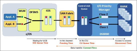
Figure 5-17 I/O request handling and WLM, SAN fabric, and DS8000 IOPM integration
This example features two applications: Appl.A and Appl.B. These applications start I/O requests that are directed to the same DS8000 rank. The WLM adds to the channel program of both I/O requests the importance and goal achievement values according to the applications service classes. These requests first arrive at SAN fabric, which gives the appropriate priority within the fabric, and then, eventually, they arrive at the DS8000 storage system. It is here that the IOPM component assigns a performance policy and then a performance group to the two I/O requests. Then, if the rank is overloaded, the IOPM begins throttling the I/O with the lower priority.
Usually when the WLM support is enabled, the volume assignment to a performance group is no longer accounted for by the IOPM. The IOPM assigns a performance group to every I/O operation according to the importance and achievement values. It then sets the proper performance policy to the single I/O operation.
This end-to-end QoS management on each individual I/O request and tight collaboration between zWLM, SAN fabric, and IOPM is unique to the DS8000 storage systems.
For more information, see DS8000 I/O Priority Manager, REDP-4760.
5.9 IBM zHyperWrite
IBM zHyperWrite™ technology is provided by the DS8880 storage system. It is used by DFSMS to help accelerate Db2 and IMS log writes in MM synchronous data replication environments when GDPS or CSM and HyperSwap technology are used. zHyperWrite is also supported in Multi-Target Metro Mirror (MTMM) environments and can be used in each relationship independently, depending on the state of the relationship.
When an application sends an I/O request to a volume that is in synchronous data replication, the response time is affected by the latency that is caused by the replication management, in addition to the latency because of the distance between source and target disk control units (10 microseconds per 1 km (0.62 miles)).
Although the latency cannot be avoided (we are limited by the speed of light), an opportunity exists to reduce the latency that is added by managing the synchronous relationship when application usage allows this technique to be used. IBM zHyperWrite combines concurrent DS8000 MM (Peer-to-Peer Remote Copy (PPRC)) synchronous replication and software mirroring through Media Manager (DFSMS) to provide substantial improvements in Db2 and IMS log write latency.
With zHyperWrite, I/O writes to the database logs are replicated synchronously to the secondary volumes by DFSMS. For each write to the primary log volume, DFSMS updates its secondary volume at the same time. Both primary and secondary volumes must be in the MM (PPRC) relationship, but z/OS instructs the DS8000 storage system to avoid the use of MM replication for these specific I/O writes to the logs.
The I/O write to the log with zHyperWrite is completed only when both primary and secondary volumes are updated by DFSMS. All I/O writes that are directed to other Db2 and IMS volumes (table spaces, indexes, and others) are replicated to the secondary volumes by DS8000 MM, as shown in Figure 5-18.

Figure 5-18 zHyperWrite active: Db2 logs updated by DFSMS
The same logic applies if you do not have dedicated volumes for Db2 logs only (that is, a mixture of Db2 logs and other Db2 data sets on the same volume). Only the I/O writes that are flagged as eligible for zHyperWrite (writes to a Db2 log data set) are replicated by DFSMS Media Manager. The other I/O writes are under DS8000 MM control.
The following prerequisites must be met for zHyperWrite enablement:
•Primary and secondary volumes with Db2 logs must be in MM (PPRC) replication.
•Primary and secondary MM volumes must be in the full duplex state.
•HyperSwap must be enabled, so use CSM or GDPS for replication management.
If the Db2 log volume (primary or secondary) is not in the full duplex state, the zHyperWrite I/O to the eligible Db2 log data set fails. When the I/O fails, DFSMS immediately tries to redrive the failed I/O to the primary volume, but this time without zHyperWrite, which gives full control to the DS8000 storage system to replicate it by using the MM, as shown in Figure 5-19.

Figure 5-19 zHyperWrite inactive: Db2 logs replicated with DS8000 Metro Mirror
Similarly, if any issues exist with FICON channels to the secondary Db2 log volume, DFSMS gives instruction to the DS8880 storage system to start MM replication.
5.9.1 zHyperWrite installation and enablement
IBM zHyperWrite support is provided on DS8000 storage system R7.4 and later. For more information about PTFs and APARs that are related to zHyperWrite, see the IBM Support website.
The zHyperWrite function is enabled by default when the required APARs and PTFs are applied and all other zHyperWrite prerequisites are met. The following zHyperWrite statement is included in the IECIOSxx member:
HYPERWRITE=YES
Alternatively, you can enable zHyperWrite by using the following z/OS command:
SETIOS HYPERWRITE=YES
Example 5-2 shows the z/OS command that is used to verify the zHyperWrite status and determine whether it is enabled or disabled.
Example 5-2 z/OS command for checking the zHyperSwap status
D IOS,HYPERWRITE
IOS634I IOS SYSTEM OPTION HYPERWRITE IS ENABLED
However, Db2 provides its own control mechanism to enable or disable the use of zHyperWrite. The required Db2 APAR PI25747 introduced a new ZPARM keyword parameter (REMOTE_COPY_SW_ACCEL) that was added to the DSN6LOGP macro; the valid keywords are ENABLE and DISABLE. By default, this parameter is disabled.
You can verify whether zHyperWrite is enabled by using the Db2 command that is shown in Example 5-3. The output of the DSNJ370I message is updated. The SOFTWARE ACCELERATION status refers to the zHyperWrite software controlled mirroring and it can be ENABLED or DISABLED.
Example 5-3 Db2 command for checking the zHyperSwap status
-DISPLAY LOG
DSNJ370I csect-name LOG DISPLAY
CURRENT COPY1 LOG = dsname1 IS pct % FULL
CURRENT COPY2 LOG = dsname2 IS pct % FULL
H/W RBA = hw-rba ,
H/O RBA = ho-rba
FULL LOGS TO OFFLOAD = nn OF mm ,
OFFLOAD TASK IS status
SOFTWARE ACCELERATION IS ENABLED
IBM zHyperWrite as an IBM Z synergy feature is available on DS8880 and DS8870 storage systems only. With the High-Performance FICON ED, it provides overall enhanced resilience for workload spikes. Because of the improved Db2 transactional latency and log throughput improvements, more room is available for workload growth and potential cost savings from workload consolidations.
5.9.2 zHyperWrite and IMS 15
IMS 15 introduced the use of DFSMS Media Manager to write data to the write-ahead data set (WADS). This change enabled IMS to use important I/O features, such as zHPF, which increases I/O throughput, and zHyperWrite, which reduces latency time for synchronous replication products.
The use of zHPF and zHyperWrite can be specially useful for data sets with high write rates, such as WADS, which increases logging speed. You can reduce service times for WADS data sets by up to 50%, depending on your environment.
For more information about WADS performance improvements, see the Storage Solutions page.
For more information about WADS support for zHyperWrite, including migration considerations, see the WADS support for zHyperWrite page.
5.10 DS8000 Copy Services performance considerations
IBM z/Architecture and its channel subsystem provide features to help mitigate the performance implications of DS8000 data replication, especially the synchronous data replication called MM.
How IBM Z I/O architecture and technology that is combined with the DS8000 storage system helps to reduce the overall response time and addresses each timing component uniquely is shown in Figure 5-20. Whether this process is done at the operating system level, channel subsystem, or the DS8000 storage system, each active component interacts with the other components to provide the maximum synergy effect possible.

Figure 5-20 How z/OS and DS8000 storage system address I/O timing components
Some of the basic ideas are also implemented in the DS8000 replication firmware, and include the enhancement to standard FCP. The pre-deposit writes improve the standard FCP and optimize the number of protocol handshakes during an MM I/O operation. Several I/O requests are sent before a handshake signals to the sending storage system that everything arrived safely at the secondary site.
The number of protocol exchanges that is needed to run the I/O chain is minimized compared to standard FCP. The goal here is to combine several aspects, such as how many I/Os to send before the handshake, considering the resources that are needed for buffers, and how smart error detection and error recovery are to run at the maximal speed and performance. This approach provides good performance with the DS8000 storage system when Copy Services functions of up to 300 km (186.41 miles) distance between sites are used.
This technology is used by DS8000 Copy Services functions and zHPF through ED II. For more information, see 5.5, “High-Performance FICON for IBM Z” on page 80.
The use of PAVs and (even better) HyperPAV with DS8000 multiple allegiance and I/O priority queuing functions can help to mitigate the potential performance effect through synchronous MM replication.
However, even without those extra performance improvement features, the MM solution as implemented in the DS8000 storage system is one of the most efficient synchronous replication solutions compared to other storage systems. With a single round trip and considering the speed of light in a non-vacuum environment at approximately 200,000 Kps, the synchronous MM impact is only 10 ms per 1 km (0.62 miles) round trip. That means the synchronous replication impact is about 1 ms when both sites are 100 km (62.13 miles) apart.
Asynchronous often has no affect on application write I/Os.
5.10.1 FlashCopy and performance considerations
FlashCopy with background copy I/Os can sometimes briefly affect application write I/Os. When application writes must be destaged during background copy I/Os, the corresponding ranks can become over committed when the source volumes experience high I/O rates at the same time.
FlashCopy with NOCOPY forces back-end I/Os through copy on writes. Before a source track is updated by an application write I/O, the source tracks are first copied to the FlashCopy target volume to preserve the data status from the last FlashCopy operation. This copy on write occurs once per track until the next FlashCopy NOCOPY operation.
When the FlashCopy target volume is a track space-efficient volume, the management impact might become visible with high write I/O rates to the source volume. Generally, a best practice is to secure performance, avoid space-efficient FlashCopy target volumes, and use a fully provisioned target volume instead. This approach also has an advantage that such a volume is not dedicated only to FlashCopy. This consideration is not applicable to GM.
Experience shows that with GM, a track space-efficient FlashCopy target volume provides sufficient performance to handle the incoming write I/O load at the GM secondary site. You are on the safe side with GM space-efficient FlashCopy target volumes when establishing the FlashCopy target volumes on the fastest DS8000 back-end storage technology. At least define the space-efficient FlashCopy repository in an extent pool with as many ranks as possible, and with them spread across as many device adapter pairs and DA pairs as possible.
Incremental FlashCopy potentially provides the best performance results, but only after a full initial copy at the time of the first FlashCopy operation is completed. After that full initial copy, no data must be moved and changed tracks are recorded as a bitmap until the next FlashCopy operation. Subsequent FlashCopy operations copy only the tracks that changed since the last FlashCopy.
An overview of what a single copy service path can perform is shown in Figure 5-21. In the days of Enterprise Storage Server Model 800, an Enterprise Storage Server PPRC FCP port over Fibre Channel links provided the fastest Copy Services function that were available in the marketplace. How well a single DS8000 FCP port performs for MM data replication today also is shown in Figure 5-21.

Figure 5-21 Single DS8870 PPRC and MM paths throughput
In the days of Enterprise Storage Server Model 800, a single PPRC FCP port was in the range of 20,000 IOPS based on 4 KB application write I/Os, and was based on 2 Gbps technology. With today’s QLogic based adapter technology and 16 Gbps technology, the improvement is almost 500%. The same range applies to the amount of data that a DS8880 16 Gb FC port can replicate between two MM ports.
These brief considerations show that the performance of DS8880 Copy Services is closely related to the synergy between IBM Z channel interface technology and the DS8880 storage system.
5.11 DS8000 storage system and z14 I/O enhancements
The latest 16 Gbps FICON (end-to-end connectivity between IBM z14 and DS8880 storage systems) provides many host I/O performance enhancements. The faster link significantly contributes to simplifying infrastructure, and reducing I/O latency for critical applications and elapsed time for I/O batch jobs. In addition, the synergy elements that were introduced with 16 Gbps FICON adapters enable even higher standards for RAS.
This section describes the following DS8000 storage system and z14 I/O enhancements:
•FICON Dynamic Routing (FIDR)
•Forward Error Correction (FEC)
•Read Diagnostic Parameters (RDP) for improved fault isolation
•SAN Fabric I/O Priority management
•zHyperLink
For information about IBM z13 I/O enhancements, see Get More Out of Your IT Infrastructure with IBM z13 I/O Enhancements, REDP-5134.
5.11.1 FICON Multihop
Planning the FICON connections for mainframe environments can be challenging, especially when your mainframe solution includes multisite requirements for HA and DR purposes and you are limited to only two cascades switches and one hop. This limitation increases the number of switches that are necessary to achieve your solution.
To overcome this limitation, IBM announced the FICON Multihop, which enables the use of up to four FICON switches or directors and up to three hops between your devices. This feature can reduce the number of switches and the complexity of your network configuration. A sample FICON configuration for geographically dispersed data centers with non-cascaded and cascaded FICON switches is shown in Figure 5-22.

Figure 5-22 Sample FICON configuration for geographically dispersed data centers
When the HCD relationship is defined, you do not define the interswitch link (ISL) connections. All of the traffic management between the ISLs is performed by the directors that are using the Fabric Shortest Path First (FSPF) protocol (see “Fabric Shortest Path First”). The HCD simply assumes that the links are present, and it requires 2-byte addressing that specifies the destination director ID and the port to be used within that director.
|
Note: Multihop is supported by using traditional static routing methods only. It is not supported by FIDR.
|
Fabric Shortest Path First
The FSPF protocol is the standardized routing protocol for Fibre Channel (FICON) SAN fabrics. FSPF is a link state path selection protocol that directs traffic along the shortest path between the source and destination that is based on the link cost.
FSPF detects link failures, determines the shortest route for traffic, updates the routing table, provides fixed routing paths within a fabric, and maintains correct ordering of frames. FSPF also tracks the state of the links on all switches in the fabric and associates a cost with each link.
The protocol computes paths from a switch to all of the other switches in the fabric by adding the cost of all links that are traversed by the path, and chooses the path that minimizes the costs. This collection of the link states (including costs) of all the switches in the fabric constitutes the topology database or link state database.
FSPF is based on a replicated topology database that is present in every switching device in the FICON SAN fabric. Each switching device uses information in this database to compute paths to its peers by way of a process that is known as path selection. The FSPF protocol provides the mechanisms to create and maintain this replicated topology database.
When the FICON SAN fabric is first initialized, the topology database is created in all operational switches. If a new switching device is added to the fabric or the state of an ISL changes, the topology database is updated in all of the fabric’s switching devices to reflect the new configuration.
Requirements and support
Several requirements must be met before you can take advantage of multihop, including requirements for IBM Z hardware, DASD/Storage, SAN Hardware, and Network/DWDM requirements.
For more information about the requirements, see the FICON Multihop: Requirements and Configurations page.
5.11.2 FICON Dynamic Routing
Static and dynamic routing policies are available on SAN fabrics; however, only static routing policies are supported for mainframe FICON users.
The SAN fabric routing policy is responsible for selecting a route for each port in the fabric. Various policy options are available from Brocade and Cisco, as listed in Table 5-1.
Table 5-1 SAN Fabric routing policies
|
Routing policy
|
Brocade
|
Cisco
|
|
Static
|
Port-based routing (PBR)
|
N/A
|
|
Static
|
Device-based routing (DBR)
|
Default static routing policy
|
|
Dynamic
|
Exchange-based routing (EBR)
|
Originator exchange ID routing (OxID)
|
PBR assigns static ISL routes, based on first come, first served at fabric login (FLOGI) time. The actual ISL that is assigned is selected in round-robin fashion. Even the ports that never send traffic to the cascaded switch are assigned ISL routes. This situation sometimes results in some ISLs being overloaded while other available ISLs are not used at all. The routing can change every time that the switch is initialized, which results in unpredictable and non-repeatable results.
When the access to the remote disks is routed only through one ISL link is shown in Figure 5-23. The remaining ISL ports are not used because other channels do not need access to the remote devices. This result occurs because of the static routing policy that assigns ISL routes to each port as it logs in to the fabric.

Figure 5-23 Static routing policy: Brocade port-based routing
Brocade DBR and the Cisco default routing policy create a set of static routes that are based on a hash of the source and destination Fibre Channel port addresses. Therefore, every flow in the fabric can take different path. For Brocade FICON Directors, DBR is more efficient at spreading the work over all the available ISLs than PBR.
Figure 5-24 shows DBR where the ISL route is assigned based on a hash of the source and destination port addresses. This method is much more likely to spread the work across all the available ISLs.

Figure 5-24 Static routing policy: Brocade device-based routing and CISCO default static routing
With z13 and DS8000 storage system R7.5 and later, FICON channels are no longer restricted to the use of static SAN routing policies for cascading FICON directors. The IBM Z feature that supports dynamic routing in the SAN is called FIDR. It is designed to support both the Brocade static SAN routing policies, including PBR and DBR, and the Brocade dynamic routing policy, which is known as EBR.
FIDR also supports both of the Cisco default static routing policies for cascaded SAN switches and the Cisco dynamic routing policy for cascaded SAN switches, which is known as OxID.
Dynamic routing dynamically changes the routes between host channels and DS8880 storage systems that are based on the Fibre Channel Exchange ID. Each I/O operation features its own exchange ID. Therefore, all available ISL ports are evenly used because the host I/O traffic is routed evenly across all ISLs.
The FIDR, which is a new feature in z13 that you use to set up dynamic routing policies in the SAN, is shown in Figure 5-25.

Figure 5-25 Dynamic routing: Brocade exchange-based routing and CISCO OxID routing
|
Note: FIDR is supported on IBM z13 and later, DS8000 storage system R7.5 and later, Brocade Fabric OS V7.4 and later, and z/OS 2.1 and later only.
|
By using the IBM Z support of dynamic routing policy, you can share SAN fabrics between FICON and FCP (PPRC) traffic and reduce overall SAN infrastructure costs. Because the ISLs can be shared between FICON and FCP traffic, extra ISL ports are not needed, and more dark fiber links between sites do not need to be leased.
Shared SAN fabric design provides simplified management, easier problem determination, and improved performance through more efficient and balanced use of ISLs. ISLs can be driven to higher use before incurring queuing delays that might result in longer I/O service times.
|
Tip: With FIDR, accommodating FCP (PPRC) traffic on the same ISL is possible because you no longer separate virtual fabrics with separate ISLs for FCP and FICON traffic.
|
This enhancement positions IBM Z and DS8880 storage system for future innovations in SAN technology.
5.11.3 Forward Error Correction
With the latest 16 Gbps Fibre Channel link speeds that were introduced in z13 and DS8880 storage systems, optical signal becomes more sensitive to environmental effects. They also can be degraded because of the poor quality of optical cables (twisting and bending), dust, or faulty optic connectors.
Many clients experienced optical signal sensitivity because of a faulty cabling infrastructure when they migrated to 8 Gbps link speed. This vulnerability increases even more with
16 Gbps. Standard tools sometimes do not reveal problems before production work is deployed. Therefore, deployment of 16 Gbps technology requires mechanisms to prevent faulty links from causing I/O errors to occur.
16 Gbps. Standard tools sometimes do not reveal problems before production work is deployed. Therefore, deployment of 16 Gbps technology requires mechanisms to prevent faulty links from causing I/O errors to occur.
IBM added FEC technology on z13 and DS8000 storage systems. This technology captures errors that are generated during the data transmission over marginal communication links. The use of FEC is auto-negotiated by the DS8880 storage system and IBM Z channels by using a standard Transmitter Training Signal (TTS). On the SAN fabric switch, you must enable ports that are connected to z13 and DS8880 storage systems to use this standard TTS auto-negotiation.
The Brocade portcfgfec command that is used for FEC enablement is shown in Example 5-4.
Example 5-4 Brocade command for FEC enablement
switch:admin> portcfgfec --enable -TTS 5
Warning : FEC changes will be disruptive to the traffic
FEC TTS is supported only on F-port.
WARNING: Enabling TTS on E-port, EX-port and D-port will disable the port.
TTS has been enabled.
|
Note: The Brocade portcfgfec command includes two parameters (FEC and TTS) that can be used to enable FEC. The FEC parameter is based on the Brocade propriety method, and the TTS method is open-standard-based, which is the same as the DS8880 storage system and z13 FICON host adapters. The TTS parameter must be used to enable end-to-end FEC between z13 and DS8880 storage systems.
|
By enabling FEC, clients see fewer I/O errors because the errors are corrected by the error correction technology in the optical transmit and receive ports. The end-to-end link should run at the 16 Gbps speed to achieve the maximum latency reduction. Moreover, the full path from the host channel through SAN fabric to the control unit should FEC enabled to minimize the risk of I/O errors.
|
Note: No configuration is needed for direct links between the DS8880 storage system and z13 channel, or direct PPRC links.
|
Fibre Channel Framing and Signaling 3 (FC-FS-3) and Fibre Channel Physical Interfaces (FC-PI-5) standards (from the T11.org1) are being updated to bring FEC to optical SAN fabric for IBM Z and the DS8880 storage system. These standards define the use of 64b/66b encoding, so the overall link efficiency improves to 97% versus 80% with previous 8b/10b encoding. FEC encoding operates at the same high efficiency and improves reliability by reducing bit errors (errors are less than 10,000 times likely to be seen). Any single bit error or up to 11 consecutive bit errors per 2112 bits can be corrected.
High-level end-to-end FEC enablement is shown in Figure 5-26.

Figure 5-26 Forward Error Correction: z13 to DS8000 storage systems
|
Note: FEC is supported on 16 Gbps links (end to end) for IBM z13 and later, DS8000 storage system R7.5 and later, Brocade FOS V7.4 and later, and z/OS 2.1 and later only.
|
5.11.4 Read Diagnostic Parameters for improved fault isolation
One of the significant challenges for clients is problem determination that is caused by faulty connections after hardware is added or upgraded. Even when the problem is detected, identifying the real root cause (that is, which part of the link is fault) can be difficult and time-consuming. Is it because of the damaged cable or connector (SFP transceiver)?
The T11 RDP standard defines a method for SAN fabric management software to retrieve standard counters that describe the optical signal strength (send and receive), error counters, and other critical information for determining the quality of the link. After a link error is detected (such as Interface Control Check: Condition Code 3, reset event, or link incident report), software can use link data that is returned from RDPs to differentiate between errors that are caused by failures in the optics versus failures that are the result of dirty or faulty links.
For example, the cable-connector path (including cleanliness of optical connectors) is diagnosed by calculating the ratio of RX LightInputPower to TX LightOutputPower. Receivers rarely fail, and the receiver sensitivity does not change. Therefore, an indicator to clean the connector warns when the receiver optical power is too low for good signal reception and the calculated ratio of RX LightInputPower to TX LightOutputPower is too low. If this RX:TX ratio continues to be low, the cable might be broken.
All of this crucial RDP data is now available in the DS8000 storage system since R7.5.
A partial output of the host port DSCLI command with the RDP data that is listed at the bottom is shown in Example 5-5. Regarding the UncorrectedBitErr and CorrectedBitErr entries, nonzero counts are expected. The counter increases during link initialization while the FEC block lock is occurring. After link init, nonzero corrected bit errors are okay because the FEC is working. Uncorrected bit errors might be an indication of link problems.
Example 5-5 DS8880 showioport command displays the RDP data
dscli> showioport -metrics I0300
Date/Time: 15 November 2016 17:28:25 CET IBM DSCLI Version: 7.8.20.248 DS: IBM.2107-75xxxxx
ID I0300
Date 11/15/2016 17:28:23 CET
...
...
CurrentSpeed (FC) 16 Gb/s
%UtilizeCPU (FC) 7 Dedicated
TxPower(RDP) -2.2 dBm(607.8 uW)
RxPower(RDP) -3.0 dBm(498.2 uW)
TransceiverTemp(RDP) 50 C
SupplyVolt(RDP) 3328.5 mV
TxBiasCurrent(RDP) 7.66 mA
ConnectorType(RDP) SFP+
TxType(RDP) Laser-SW
FECStatus(RDP) Inactive
UncorrectedBitErr(RDP) -
CorrectedBitErr(RDP) -
The intended use of the RDP to retrieve programmatically diagnostic parameters to assist you in finding the root cause for problematic links in the SAN environment is shown in Figure 5-27.

Figure 5-27 Read Diagnostic Parameters that are used to improved fault isolation
New z/OS health checks occur when the end-to-end link speeds are inconsistent and if all paths to a control unit have inconsistent link speeds. These checks simplify diagnosing performance problems and reduce the number of useless repair actions.
5.11.5 zHyperLink
The business requirements for faster transactions and lower response times for applications drove new technology to reduce the latency that is related to retrieving data from back-end storage, such as Easy Tier and flash storage. Although these solutions help address the time that is required to read the data from your physical media, other parts of your I/O processing can also use valuable amounts of time and affect your latency.
zHyperLink introduced on IBM z14 aims to provide a short distance direct connection of up to 150 meters (492.12 feet). zHyperLink is a new synchronous I/O paradigm. This paradigm eliminates z/OS dispatcher delays, I/O interrupt processing, and the time that is needed to reload the processor cache that occurs after regaining control of the processor when I/O completes. zHyperLink delivers up to 10 times latency improvement. zHyperLink improves application response time, which cuts I/O sensitive workload response time in half without significant application changes.
zHyperLink and zHPF
Although zHyperLink represents a substantial enhancement over FICON connections, it does not replace these connections. Instead, zHyperLink works with FICON or zHPF to reduce application latency, the workload that is transferred by zHPF reduces with zHyperLink implementation. Not all I/Os are eligible for zHyperlink. Additionally, if a zHyperlink I/O is not successful (for example, because of a read cache miss), the I/O is redriven over FICON.
zHyperLink is a PCIe connection and does not reduce the physical number of current zHPF connections.
The different latency times for zHyperLink and zHPF are shown in Figure 5-28.

Figure 5-28 zHyperLink and zHPF response times
zHyperLink considerations
A few conditions must be met before you can use zHyperLink. First, zHyperLink is available only to z14 and later hardware. It is not possible to install or use zHyperLink on previous hardware versions.
The zHyperLink hardware is designed for short distance communication of up to 150 meters (492.12 feet), so your DS8880 storage system must be no further than this length from your IBM Z hardware. Additionally, the IBM Z and the DS8880 hardware must have the zHyperLink hardware installed to communicate.
zHyperLink and synchronous I/O
zHyperLink can provide low latency for I/Os, and can deliver an I/O operation in less than
20 microseconds in some scenarios. The time that is spent with interrupt handling, CPU dispatch time, and reload L1/L2 cache can also increase your I/O time (see Figure 5-28).
20 microseconds in some scenarios. The time that is spent with interrupt handling, CPU dispatch time, and reload L1/L2 cache can also increase your I/O time (see Figure 5-28).
When an application (in this case, Db2) requests an I/O through zHyperLink, a synchronous I/O operation is requested. Therefore, the task is not dispatched from the CPU while the I/O is performed.
The workflow of an I/O operation that defines whether a zHyperlink synchronous I/O operation is attempted is shown in Figure 5-29.

Figure 5-29 I/O operation work flow
As shown in Figure 5-29, the I/O process flow includes the following steps:
1. The I/O drivers request a synchronous execution. The system checks whether the I/O is eligible for synchronous I/O, and if so, it is directed for synchronous IOS through zHyperLink.
2. If the I/O is returned in an acceptable amount of time, the I/O is returned to the I/O Driver.
3. If the I/O is not returned in an acceptable amount of time (for example, if the data is not in the DS8880 cache and a prefetch is necessary), the request is returned to the I/O Driver.
4. The I/O driver requests the I/O to be performed through the heritage IOS.
5. When the I/O response is received, it is returned to the I/O driver the same way it is done today.
|
Note: Because the prefetch is requested when the synchronous I/O is attempted, the subsequent heritage I/O can still perform better than a request that did not attempt a synchronous I/O.
|
Other considerations
You can have up to 16 zHyperLink Express adapters per z14, for a total of 32 ports. These adapters do not take up fanout slots like short distance coupling. Each port can be shared among up to 16 LPARs, and have a maximum suggested PCIE Function IDs (PFIDs) per zHyperLink per LPAR. As of this writing, the DS8880 storage system can have up to 16 zHyperLink connections. The number of connections depends on the model (number of I/O enclosures and cores, as show in Table 5-2).
Table 5-2 zHyperLink configuration summary
|
System/Model
|
Cores per processor
|
zHyperLink supported
|
Maximum zHyperLink connections (increments of 2)
|
|
DS8884 / DS8884F
|
6
|
NO
|
NONE
|
|
12
|
YES
|
4
|
|
|
DS8886 / DS8886F
|
8
|
NO
|
NONE
|
|
16
|
YES
|
8
|
|
|
24
|
YES
|
12
|
|
|
DS8888 / DS8888F
|
24
|
YES
|
8
|
|
48
|
YES
|
16
|
A DS8884/F storage system with six cores can be concurrently upgraded to 12 cores by using feature code (FC #4425).
zHyperLink allows the following interconnections:
•One z14 to one DS8880 storage system by using multiple zHyperLink connection pairs
•Multiple z14 mainframes to a single DS8880 storage system
•Multiple DS8880 storage systems to a single z14 mainframe
Initially, only Db2 can use zHyperLink for random 4 KB or smaller reads and writes (Db2 Read and, as of this writing, just Db2 logs are eligible for write operations).
|
Note: For writes, zHyperwrite is required, meaning that z/OS performs zHyperlink operations in parallel to the DS8000 storage system (see 5.9, “IBM zHyperWrite” on page 92).
|
Before you can configure and activate your zHyperLink connection in your host, you must also enable the zHyperLink in your DS8000 DASD controller. You activate zHyperLink by logging on with a user with administrator privileges, and select Settings, and select System.
In the next window, select the zHyperLink tab, and then select the I/O Read Enabled or I/O Write Enabled check box (select both to enable Read and Write). After you enable zHyperLink, you must save the changes in your configuration.
A sample zHyperLink enablement window that uses DS8880 Release 8.51 code and the corresponding GUI is shown in Figure 5-30.

Figure 5-30 zHyperLink enablement window (DS8000 storage system R5.1)
IBM zHyperLink is supported on native z/OS operating systems only. It is not supported on guest LPARS under z/VM or other operating systems. It was developed for IBM Db2 for z/OS.
The use of the MISSINGFIX report is required to determine whether any APARs exist that are applicable and are not yet installed. The REPORT MISSINGFIX command checks the zones that are specified on the ZONES operand and determines whether any missing fixes exist based on the fix categories of interest.
Run the SMP/E REPORT MISSINGFIX ZONES (<your zone names>) FIXCAT (IBM.Function.zHyperLink) command and install all the fixes that are listed. Example 5-6 shows a sample MISSINGFIX JCL.
Example 5-6 Sample SMP/e control cards with the FIXCAT option
SET BOUNDARY (GLOBAL) .
REPORT
MISSINGFIX
ZONES (
<your zone names>
)
FIXCAT(
IBM.Function.zHyperLink
) .
Also, consider checking IBM.Device.Server.z14-3906* for z14 and IBM.Device.Server.z14-3906.zHighPerformanceFicon for zHPF.
By default, the zHyperLink functions are disabled in z/OS. To enable z/OS for zHyperLink read/write processing, use the SETIOS IBM MVS™ system command after an IPL, or use the IECIOSxx parmlib to enable zHyperLink processing during IPL, as shown in Example 5-7.
Example 5-7 zHPF, zHyperLink, and HyperWrite parm on the IECIOSxx parmlib
ZHPF=YES
ZHYPERLINK,OPER=ALL|READ|WRITE|NONE
HYPERWRITE=YES
|
Note: To activate zHyperLink, IOPM must be disabled. IOPM must be turned off at the storage system level. This feature then is off for all data, even if the data is not eligible for zHyperLink. Therefore, I/O prioritization for IBM IMS data (and other data) might be effected.
|
To disable IOPM, log in to the DS8000 Storage Management interface as a user with administrator privileges, select the Settings option, select System, click the Advanced tab, click Function Settings, and select Disable for I/O Priority Manager mode, as shown in Figure 5-31.

Figure 5-31 Setting I/O Priority Manager Disable
For more information about the configuration, feature codes, and requirements for zHyperLink on the DS8880 storage system, see the following documents:
•IBM DS8880 Architecture and Implementation (Release 8.51), SG24-8323
•Getting Started with IBM zHyperLink for z/OS, REDP-5493
5.12 IBM zEnterprise Data Compression
Another synergy component is the IBM zEnterprise® Data Compression (zEDC) capability and the hardware adapter zEDC Express, which can be used with z/OS V2.1 and later.
zEDC is optimized to be used with large sequential files (but not limited to such files) and improve disk usage with a minimal effect on processor usage.
zEDC can also be used for Data Facility Storage Management Subsystem Data Set Services (DFSMSdss) dumps and restores and DFSMS Hierarchical Storage Manager (DFSMShsm) when DFSMSdss is used for data moves.
An example of a zEDC compression result is shown in Figure 5-32.

Figure 5-32 zEDC compression numbers
For more information about zEDC, see Reduce Storage Occupancy and Increase Operations Efficiency with IBM zEnterprise Data Compression, SG24-8259.
5.13 Transparent Cloud Tiering
Good storage management practices are based on the principle that physical space often is configured in logical pools that can be dynamically reconfigured to increase or decrease the storage capacity that is available for use. This reconfiguration should also be transparent to the user.
Storage Cloud on mainframes introduces a new storage tier that can be used to provide extended storage capacity at a lower cost while making the data available from different locations.
The Transparent Cloud Tiering (TCT) function from the DS8880 storage system provides a gateway to convert the DS8880 block storage data to Object Storage format for storing data on private or public clouds (TCT supports IBM Cloud™ Object Storage, Amazon S3 API, and OpenStack Swift).
From a z/OS perspective, there is a MIPS reduction by using direct data transfer from the DS8880 storage system to Object Storage. DFSMShsm and DFSMSdss are used to store and retrieve data from the cloud, as shown in Figure 5-33.
TCT provides support to migrate and recall data sets to volumes that participate in Simplex, FlashCopy, 2-site MM, GM, and Metro-Global Mirror relationships.

Figure 5-33 Transparent Cloud Tiering data movement.
To use TCT, you must fulfill the following requirements:
•Ethernet connections on the DS8880 storage system
•z/OS levels
•DS8880 release level
•Cloud APIs support
•Authentication information from your cloud service provider or administrator
•TLS/SSL considerations
To learn about these requirements and how to configure your system to use TCT, see IBM DS8880 and z/OS DFSMS: Transparent Cloud Tiering, SG24-8381.
TCT services use up to two 10 Gbit or two/four 1 Gb Ethernet ports in each of the DS8880 processors. This Ethernet connectivity is also required from the mainframe to either the DS8880 storage system or the Object Storage cloud server, depending on the cloud type chosen.
..................Content has been hidden....................
You can't read the all page of ebook, please click here login for view all page.