

IBM DS8900F Management Console planning and setup
This chapter describes the planning tasks that are involved in the setup of the required
IBM DS8900F Management Console (MC), which is also known as the Hardware Management Console (HMC).
IBM DS8900F Management Console (MC), which is also known as the Hardware Management Console (HMC).
This chapter covers the following topics:
6.1 DS8900F Management Console overview
The MC is a multi-purpose piece of equipment that provides the services to configure and manage storage, and manage several of the operational aspects of the storage system. It also provides the interface where service personnel perform diagnostic and repair tasks.
The MC does not process any of the data from hosts. It is not even in the path that the data takes from a host to the storage. The MC is a configuration and management station for the whole DS8900F system.
The DS8900F includes a Management Enclosure (ME). This enclosure contains two MCs, which is standard for redundancy reasons, but the ME contains other essential management components too, which are explained in 6.1.1, “Management Enclosure” on page 168.
The MC, which is the focal point for DS8900F management, includes the following functions:
•DS8900F power control
•Storage provisioning
•Storage system health monitoring
•Storage system performance monitoring
•Copy Services (CS) monitoring
•Embedded IBM Copy Services Manager
•Interface for onsite service personnel
•Collection of diagnostic and Call Home data
•Problem management and alerting
•Enables remote support access
•Storage management through the DS GUI
•Connection to IBM Security Guardium Key Lifecycle Manager or other supported external key manager for encryption management functions, if required
•Connection to an external IBM Copy Services Manager or IBM Spectrum Control
•Interface for Licensed Internal Code (LIC) and other firmware updates
6.1.1 Management Enclosure
The ME is a 2U chassis containing the following components:
•Two MCs (MCs or HMCs) as standard
•Two Ethernet switches
•Two rack power control cards (RPCCs)
•Two power supply units (PSUs) to power the ME components
•One Local or Remote switch assembly
•Internal cabling for communications and power for each of the components
Figure 6-1 shows a ME.

Figure 6-1 Management Enclosure
|
Note: The location of the ME can be slightly different from what is shown in Figure 6-1 because there are many rack configurations, such as IBM DS8980F model 998,
IBM DS8950F model 996, IBM DS8910F model 994, and IBM DS8910F Rack-Mounted model 993 that can fit into an existing 19-inch form-factor rack. On racked DS8900F systems, the ME is always in the base frame (Rack 1). |
The ME is designed to create a compact container for all essential system management components that otherwise would be mounted around the rack as in former IBM DS8000 models.
Figure 6-2 shows the layout of the components of the ME.

Figure 6-2 Management Enclosure component layout
The ME provides internal communications to all of the modules of the DS8900F system. It also provides external connectivity by using two Ethernet cables from each HMC for remote management, and provides keyboard, mouse, and video connectivity from each HMC for local management. Cables are routed from the MCs to the rear of the ME through a cable management arm (CMA).
6.1.2 Management Console hardware
The MC itself consists of a small form-factor (SFF) personal computer running Red Hat Linux. Using an SFF personal computer makes the MC efficient in many ways, including power consumption. It supports the DS8900F hardware and firmware installation and maintenance activities.
Because of the small width, both primary and secondary MCs are mounted in the front of the ME next to each other.
There is an 1U keyboard and display tray that are available. For racked DS8980F, DS8950, and DS8910F model 994 systems, you must order one (use Feature Code 1765). For the Flexibility Class Rack-Mounted model 993, it is optional. For more information, see IBM DS8910F Model 993 Rack-Mounted Storage System Release 9.1, REDP-5566.
The MC connects to the customer network and provides access to functions that can be used to manage the DS8900F. Management functions include logical configuration, problem notification, Call Home for service, remote service, and CS management.
These management functions can be performed from the DS GUI, Data Storage Command-Line Interface (DS CLI), or other storage management software that supports the DS8900F.
For example, clients who use an external IBM Copy Services Manager for advanced functions, such as Metro Mirror (MM) or FlashCopy are communicating to the storage system by connecting the IBM Copy Services Manager server to the HMCs as management entry point.
The MC provides connectivity between the DS8000 and Encryption Key Manager (EKM) servers (Security Guardium Key Lifecycle Manager), and also provides the functions for remote call home and remote support connectivity.
The MCs are equipped with Ethernet connections for the client’s network. For more information, see 6.1.3, “Private and Management Ethernet networks” on page 171.
To provide continuous availability to the MC functions, the DS8900F includes a second MC by default. The secondary HMC is needed for redundancy, such as for encryption management or CS functions. For more information about the secondary MC, see 6.6, “Secondary Management Console” on page 196.
HMC hardware revision
The amount of memory, the solid-state drive (SSD) capacity, and the type of processor that is used in the HMCs might change with the DS8900F release.
Use the DS CLI command lshmc to show the HMC types, whether both HMCs are online, and their amount of disk capacity and memory, as shown in Example 6-1.
Example 6-1 The lshmc command
dscli> lshmc
Name State Role Release Management-IP Location-Code Machine-Type Machine-Model Memory Disk
==========================================================================================================================
dlr20 Online Primary(1) R9.2 bundle 89.20.131.0 10.11.236.76 U1700L47.I355527 1700 L47 32 GB 256 GB
dlr20-b Online Secondary(2) R9.2 bundle 89.20.131.0 10.11.236.77 U1700L47.I355529 1700 L47 32 GB 256 GB
6.1.3 Private and Management Ethernet networks
The HMCs communicate with the storage facility internally through a pair of redundant Ethernet networks, which are designated as the black network and the gray network. There are two switches that are isolated from each other, and they are in the ME.
Inside the ME, the switch ports of the internal black and gray network switches are routed from inside the ME to an external breakout at the rear of the ME by using short patch cables to make the ports accessible from outside.
Each central processor complex (CPC) flexible service processor (FSP) and each CPC logical partition (LPAR) network are connected to both switches. Each of these components (FSP and LPAR) uses their own designated interface for the black network and another interface for the gray network. These components are connected to the external breakout ports of the ME.
Each MC also uses two designated Ethernet interfaces for the internal black (eth0) and gray (eth3) networks. The MCs that are installed in the ME are already connected internally to the switches without routing them to connections outside of the ME.
Additionally, an MC contains a third Ethernet interface (eth2) for the customer network connection to allow management functions to be started over the network. This customer network connection is routed from the MC directly to the rear of ME to its own breakout ports.
For particular circumstances where the customer needs a second Ethernet interface for management reasons, you can place a Request for Price Quotation (RPQ) to have a USB Ethernet adapter (eth1) added to the MC. This adapter can be used to connect the HMC to two separate customer networks, usually for separating internet traffic (call home and remote access) from storage management tasks (DS GUI, DS CLI, and IBM Copy Services Manager).
Figure 6-3 shows these internal and external network connections.
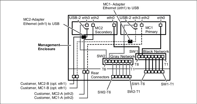
Figure 6-3 ME and MC internal network connections
|
Important: The internal Ethernet switches that are shown in Figure 6-3 and Figure 6-4 on page 173 (the black and gray private networks) are for DS8900F internal communication only. Do not connect these ports directly to your network. There is no connection between the customer network interfaces and the black and gray network to keep them isolated.
|
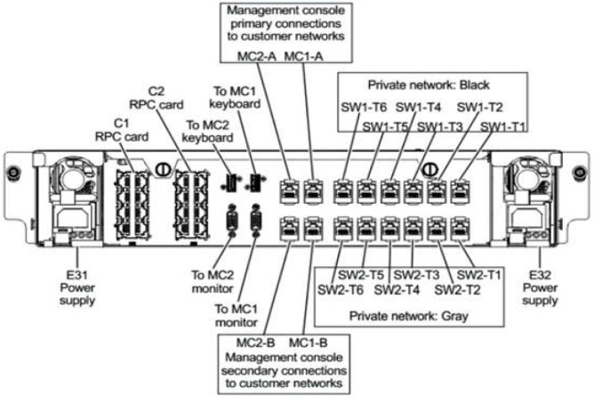
Figure 6-4 ME external connections
Intelligent Power Distribution Units
In racked configurations such as DS8980F, DS8950F, and DS8910F model 994 systems, the rack power control is managed through the Ethernet-managed intelligent Power Distribution Units (iPDUs). For rackless configurations such as DS8910F model 993, the iPDUs are optional.
An HMC communicates to these iPDUs by using the Ethernet network, and it manages and monitors the system power state, iPDU configuration, System AC power on and off, iPDU firmware update, iPDU health check and error, and power usage reporting.
The iPDUs’ network interfaces are also connected to the external ports of the ME to reach the black and gray network switches. They are distributed over the black and gray network, which means iPDUs that belong to one power domain (usually on the left side of the rear of the rack) connect to a gray network switch and the iPDUs that belong to the other power domain (usually on the right side of the rear of the rack).
For the rack-mounted DS8980F and DS8950F systems, you may add an expansion frame model E96. Two cascaded switches are added to the base frame to connect the additional iPDUs of the expansion rack to the ME switches.
One 1U 24-port Ethernet switch is added for the black network and one 24-port is added for the gray network. Each of them has an uplink to the related ME switch port of their designated black or gray network. The 2U space that is required is already reserved at the bottom of the base rack.
Figure 6-5 and Table 6-1 show how each port is used on the pair of DS8900F ME Ethernet switches.

Figure 6-5 ME rear Ethernet breakout
Table 6-1 Functional connections of the switch ports
|
From ME rear outside connectors
|
Connects to
|
|
SW1-T1 black
|
Unused or iPDU-E22 (upper right from rear) or uplink to 24-port cascaded Ethernet switch black network
|
|
SW2-T1 gray
|
Unused or iPDU-E21 (upper left from rear) or uplink to 24-port cascaded Ethernet switch gray network
|
|
SW1-T2 black
|
Unused or iPDU-E24 lower right from rear
|
|
SW2-T2 gray
|
Unused or iPDU-E23 lower left from rear
|
|
SW1-T3 black / SW2-T3 gray
|
Upper CPC/CEC1 FSP black / gray
|
|
SW1-T4 black / SW2-T4 gray
|
Lower CPC/CEC1 FSP black / gray
|
|
SW1-T5 black / SW2-T5 gray
|
Upper CPC/CEC1 LPAR black / gray
|
|
SW1-T6 black / SW2-T6 gray
|
Lower CPC/CEC2 LPAR black / gray
|
|
SW1-T7 black / SW2-T7 gray
|
MC1 eth0 black / MC1 eth3 gray
|
|
SW1-T8 black / SW2-T8 gray
|
MC2 eth0 black / MC2 eth3 gray
|
6.2 Management Console software
The MC, which is based on Linux, includes the following application servers:
•DS8000 Storage Management GUI
•National Institute of Standards and Technology (NIST) Web UI (WUI)
•IBM Copy Services Manager
•RESTful application programming interface (API) services
•DS CLI
•IBM Enterprise Storage Server® Network Interface (IBM ESSNI) server
The Management Console also provides the interfaces for IBM Spectrum Control,
IBM Storage Insights, and the DS CLI to connect to the DS8900F remotely.
IBM Storage Insights, and the DS CLI to connect to the DS8900F remotely.
|
Note: The DS Open API with IBM System Storage Common Information Model (CIM) agent is no longer supported. The removal of the CIM Agent simplifies network security because fewer open ports are required.
|
6.2.1 DS Storage Management GUI
The DS GUI is used to perform logical configuration and storage management tasks. It can be accessed in the following ways:
•Remotely by using a web browser that is connected to the DS8900F HMC (or MC)
•From the local console of the HMC directly
•By using IBM Spectrum Control, which has connectivity to the HMC
For more information, see 9.2.1, “Accessing the DS GUI” on page 235.
6.2.2 Data Storage Command-Line Interface
The Data Storage Command-Line Interface (DS CLI), which must be run in the command environment of an external workstation, is a second option to communicate with the MC. The DS CLI is a good choice for configuration tasks when many updates are needed. A copy of DS CLI is installed locally on the HMC, and it can be used when servicing the machine from the local console.
|
Note: The DS Storage Management GUI also provides a built-in DS CLI. Look for the console icon on the lower left of the browser window after logging in.
|
For more information about DS CLI usage and configuration, see Chapter 10, “IBM DS8900F Storage Management Command-line Interface” on page 339. For a complete list of DS CLI commands, see IBM DS8000 Series: Command-Line Interface User’s Guide, SC27-9562.
6.2.3 RESTful application programming interface
DS8900F RESTful API services provide an easy-to-use application programming interface (API) to manage DS8900F through communication with the MC. The RESTful API communicates with RESTful services that run on the MC. The RESTful services in turn interact with the IBM ESSNI server software that runs on the MC to pass requests and receive replies. For more information about the RESTful API, see IBM DS8880/DS8870 RESTful API Guide, SC27-9235.
6.2.4 IBM Copy Services Manager interface
IBM Copy Services Manager is preinstalled on the DS8900F MC. You can use it to manage and automate replication and disaster recovery (DR) for up to four DS8000 storage systems.
This feature removes the requirement for an external server to host IBM Copy Services Manager, which provides savings on infrastructure costs and operating system (OS) licensing. Administration costs are also reduced because the embedded IBM Copy Services Manager instance is upgraded through the DS8900F code maintenance schedule, which is performed by IBM support personnel.
|
Important: Avoid configuring the primary HMC and the secondary HMC of the same storage system as the active and standby IBM Copy Services Manager servers within a CS environment.
|
6.2.5 Updating the embedded IBM Copy Services Manager
With the embedded IBM Copy Services Manager on HMC, the IBM Copy Services Manager release that came initially installed on the DS8000 HMC might be outdated. IBM Copy Services Manager can be updated independent of a microcode update.
|
Important: Updating the HMC embedded IBM Copy Services Manager must be done exclusively through the IBM DS CLI tool that is installed on the workstation, laptop, or server.
|
Update IBM Copy Services Manager on the HMC by completing the following steps:
1. Verify the current level of the DS CLI.
2. Verify the current level of IBM Copy Services Manager on the HMC.
3. Download selected releases of DS CLI, if necessary, and IBM Copy Services Manager from IBM Fix Central.
4. Update DS CLI, if needed.
5. Update IBM Copy Services Manager on the HMC.
The DS8000 Code Recommendation page provides a link to the DS8900F code bundle information page, as shown in Figure 6-6 and Figure 6-7.

Figure 6-6 DS8900F Code Recommendation page
Figure 6-7 Recommended DS CLI release
Verifying the current level of IBM Copy Services Manager on the HMC
To verify the current IBM Copy Services Manager release that is installed on a DS8000 HMC, run the lssoftware DS CLI command:
lssoftware -l -type csm -hmc all
Example 6-2 on page 177 shows an example where the IBM Copy Services Manager release on both HMCs is 6.2.9.1.
Example 6-2 Current IBM Copy Services Manager release
dscli> lssoftware -l -type csm -hmc all
Type Version Status HMC
========================================
CSM V6.2.9.1-a20200804-1704 Running 2
CSM V6.2.9.1-a20200804-1704 Running 1
dscli>
Downloading IBM Copy Services Manager for an upgrade on the HMC
The IBM Copy Services Manager installation file must be downloaded on the same workstation or server where the DS CLI was previously installed.
Complete the following steps. Assume that IBM Copy Services Manager 6.3.0 is the release that will be installed.
1. On the IBM Fix Central page, select IBM Copy Services Manager as the product, 6.3.0.0 as the installed version, and Linux as the platform. Figure 6-8 shows a summary of selected options.

Figure 6-8 Selected IBM Copy Services Manager Version for HMC
|
Note: The HMC OS is Linux. Ensure that the correct platform is selected.
|
2. Be sure to download the correct Linux-x86_64 release. Figure 6-9 shows the correct package type selected. Check the Release Notes, and if there is a newer fix pack file, you can use it instead.
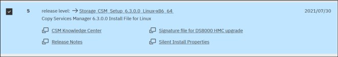
Figure 6-9 IBM Copy Services Manager Linux-x86_64 package
3. When the download process is complete, note the folder path where the files were stored. In our example, the files are stored in the folder C:DownloadsCSM_Linux, as shown in Figure 6-10.
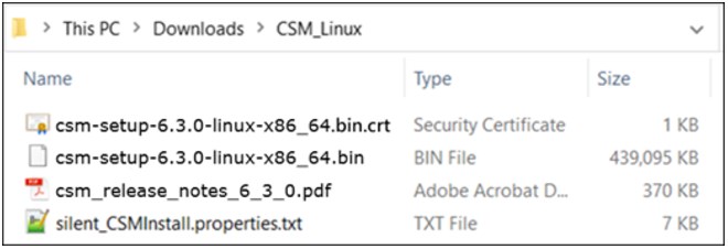
Figure 6-10 Downloaded IBM Copy Services Manager files
Updating IBM Copy Services Manager on the HMC by using the DS CLI
Update the IBM Copy Services Manager on each HMC. In a dual HMC environment, update one IBM Copy Services Manager instance at a time.
|
Note: If your IBM Copy Services Manager installation has active CS sessions, you must follow best practices while applying maintenance to an active management server.
Note: The Active and Standby servers must be updated concurrently. Failure to do so results in the inability to connect to the other server.
|
The DS CLI command that is used for the IBM Copy Services Manager update is installsoftware. You can find more information about the command in IBM Documentation.
Table 6-2 describes the parameters that are necessary for the installsoftware command.
Table 6-2 DS CLI installsoftware parameters
|
Parameter
|
Explanation
|
|
-type csm
|
The software type of the installation package.
|
|
-loc software_package
|
The full path of the installation package to be installed.
|
|
-certloc certificate_location
|
The full path of the certificate file location.
|
|
-hmc 1 | 2 | all
|
Specifies the primary or secondary HMC where the software is to be installed. The default is all.
|
|
Note: Ensure that no spaces are included in the path that you specify for the location of the software package and certificate file.
Note: In addition to the standard 1751 port, DS CLI also uses port 1755 (TCP protocol) to transfer the IBM Copy Services Manager installation file to the HMC. That port must be open on any physical or software firewall standing between the workstation where DS CLI is installed and the DS8000 HMCs.
|
To effectively run the command, you must use a DS8000 user ID that is part of the Administrator role (for example, the default admin user ID).
Example 6-3 shows how the IBM Copy Services Manager on HMC1 was updated by using DS CLI.
Example 6-3 IBM Copy Services Manager update on HMC1
dscli> installsoftware -type csm -loc
C:DownloadsCSM_Linuxcsm-setup-6.3.0-linux-x86_64.bin -certloc
C:DownloadsCSM_Linuxcsm-setup-6.3.0-linux-x86_64.bin.crt -hmc 1
CMUC00516I installsoftware: The file uploaded successfully.
CMUC00517I installsoftware: Software CSM is successfully installed on 1.
dscli> lssoftware
Type Version Status
====================================
CSM V6.3.0.0-a20210622-1237 Running
CSM V6.2.9.1-a20200804-1704 Running
The next step is to update IBM Copy Services Manager on HMC2, as shown in Example 6-4.
Example 6-4 IBM Copy Services Manager update on HMC2
dscli> installsoftware -type csm -loc
C:DownloadsCSM_Linuxcsm-setup-6.3.0-linux-x86_64.bin -certloc
C:DownloadsCSM_Linuxcsm-setup-6.3.0-linux-x86_64.bin.crt -hmc 2
CMUC00516I installsoftware: The file uploaded successfully.
CMUC00517I installsoftware: Software CSM is successfully installed on 2.
dscli> lssoftware
Type Version Status
====================================
CSM V6.3.0.0-a20210622-1237 Running
CSM V6.3.0.0-a20210622-1237 Running
The IBM Copy Services Manager upgrade is now complete.
6.2.6 Web User Interface
The HMC Web User Interface (WUI) is used for the initial setup of the HMC and for servicing the hardware of the DS8900F. It provides remote access to system utilities.
To log in to the WUI, complete the following steps:
1. Start the Storage Management GUI, as shown in Figure 6-11. Click the Service icon (wrench) to access the Service MC.
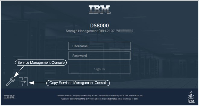
Figure 6-11 DS Storage Management GUI Logon window
2. Click Log on and launch the Hardware Management Console web application to open the login window, as shown in Figure 6-12 on page 181, and log in. The default user ID is customer and the default password is cust0mer.
|
Important: Make sure to change the default password. The user credentials for accessing the Service Management Console (HMC) are managed separately from the ones that are used with DS CLI and the Storage Management GUI. For more information about HMC user management, see 6.5.3, “Service Management Console User Management” on page 189.
|

Figure 6-12 Service Management Console application
3. If you are successfully logged in, you see the MC window, in which you can select
Status Overview to see the status of the DS8900F. Other areas of interest are shown in Figure 6-13.
Status Overview to see the status of the DS8900F. Other areas of interest are shown in Figure 6-13.
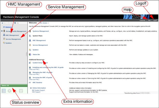
Figure 6-13 Web UI main window
Because the MC web UI is mainly a services interface, it is not covered here. For more information, see the Help menu.
6.2.7 IBM ESSNI server
IBM ESSNI is the logical server that communicates with the DS GUI server and interacts with the two processor nodes of the DS8900F. It is also referred to as the DS Network Interface (DSNI).
6.3 Management Console activities
This section covers planning and maintenance tasks for the DS8900F MC. For more information about overall planning, see Chapter 5, “IBM DS8900F physical planning and installation” on page 141.
6.3.1 Management Console planning tasks
To plan the installation or configuration of the MC, you must do the following tasks:
•A connection to the client network is needed at the base rack for the primary MC. Another connection is also needed at the location of the secondary MC. The connections must be standard CAT5/6 Ethernet cabling with RJ45 connectors.
•IP addresses for the primary and secondary MCs are needed. The DS8900F can work with IPv4 and IPv6 networks. For more information about procedures to configure the DS8900F MC for IPv6, see 6.4, “Management Console network settings” on page 185.
•Most users access the DS GUI remotely through a browser. You can also use
IBM Spectrum Control in your environment to access the DS GUI.
IBM Spectrum Control in your environment to access the DS GUI.
•The web browser to be used on any administration workstation must be supported, as described in IBM DS8900F Introduction and Planning Guide, SC27-9560.
•The IP addresses of Simple Network Management Protocol (SNMP) recipients must be identified if the client wants the DS8900F MC to send traps to a monitoring station.
•Email accounts must be identified if the client wants the DS8900F MC to send email messages for problem conditions.
•The IP addresses of Network Time Protocol (NTP) servers must be identified if the client wants the DS8900F MC to use NTP for time synchronization.
•When a DS8900F is ordered, the license and certain optional features must be activated as part of the customization of the DS8900F. For more information, see Chapter 7, “IBM DS8900F features and licensed functions” on page 199.
•The installation tasks for the optional external MC must be identified as part of the overall project plan and agreed upon with the responsible IBM personnel.
|
Important: Applying feature activation codes is a concurrent action.
|
6.3.2 Planning for Licensed Internal Code upgrades
The following tasks must be considered regarding the LIC upgrades on the DS8900F:
•LIC changes
IBM periodically releases changes to the DS8900F series Licensed Machine Code (LMC). Customers can check the IBM Support site for the latest Flashes, Alerts and Bulletins, and keep up to date by subscribing to IBM Support Notifications.
•LIC installation options
There are three installation types available, depending on the support contract:
– On-site Code Load
An IBM Systems Service Representative (IBM SSR) goes onsite to install the changes.
– Remote Code Load (RCL)
IBM Remote Support personnel install the LIC remotely.
– Customer Code Load
As of Release 9.3, customers can perform the installation.
•DS CLI Compatibility
Check whether the new LIC requires new levels of DS CLI. Plan on upgrading them on the relevant workstations, if necessary.
•Code prerequisites
When you are planning for initial installation or for LIC updates, ensure that all prerequisites for the environment are identified correctly, which include host OS versions, fixes, host bus adapter (HBA) levels, interconnect and fabric types, and OS versions.
DS8900F interoperability information is available at the IBM System Storage Interoperation Center (SSIC).
To prepare for downloading the drivers, see the “Interoperability Search Details” report in SSIC, which provides an end-to-end support matrix from the host to the DS8900F, and covers all versions of OS, multipathing software, and firmware. This check is necessary to ensure that the DS8900F storage subsystem is in a supported environment.
|
Important: The SSIC includes information about the latest supported code levels. This availability does not necessarily mean that former levels of HBA firmware or drivers are no longer supported. Some host type interoperability, such as NetApp ONTAP, might need to be confirmed in the vendor’s support matrix. If you are in doubt about any supported levels, contact your IBM SSR.
Never proceed with a LIC update without adhering to all prerequisites.
|
•Maintenance windows
The LIC update of the DS8900F is a nondisruptive action. Scheduling a maintenance window with added time for contingency is still a best practice. Also, plan for sufficient time to confirm that all environment prerequisites are met before the upgrade begins.
For more information about LIC upgrades, see Chapter 11, “Licensed Machine Code” on page 405.
6.3.3 Time synchronization
With the DS8900F, the MC can use the NTP service. Clients can specify NTP servers on their internal or external network to provide the time to the MC. It is the client’s responsibility to ensure that the NTP servers are working, stable, and accurate. An IBM SSR enables the MC to use NTP servers (ideally at the time of the initial DS8900F installation). Changes can be made by the client by using the Change Date and Time action under MC Management on the MC.
|
Important: For correct error analysis, the date and time information must be synchronized on all components in the DS8900F environment. These components include the DS8900F MC, the attached hosts, IBM Spectrum Control, and DS CLI workstations.
|
6.3.4 Monitoring DS8900F with the Management Console
A client can receive notifications from the MC through traps and email messages. Notifications contain information about your storage complex, such as open serviceable events. You can choose one or both of the following notification methods:
•Traps
For monitoring purposes, the DS8900F uses traps. A trap can be sent to a server in the client’s environment, perhaps with System Management Software, which handles the trap that is based on the Management Information Base (MIB) that was delivered with the DS8900F software. A MIB that contains all of the traps can be used for integration purposes into System Management Software.
The supported traps are described in the documentation that comes with the LIC on the CDs that are provided by the IBM SSR. The IP address to which the traps must be sent must be configured during initial installation of the DS8900F. For more information about the DS8900F and monitoring, see Chapter 12, “Monitoring and support” on page 423.
•Email
When you enable email notifications, email messages are sent to all the addresses that are defined on the MC whenever the storage complex encounters a serviceable event or must alert individuals to other information.
During the planning process, create a list of the individuals who need to be notified.
Additionally, when the DS8900F is attached to an IBM Z system server, a service information message (SIM) notification occurs automatically. A SIM message is displayed on the OS console if a serviceable event occurs. These messages are not sent from the MC, but from the DS8900F through the channel connections that run between the server and the DS8900F.
6.3.5 Event notification through syslog
To meet ever increasing security requirements, the DS8900F supports security and logging events that are forwarded to a syslog server. This capability was previously available only on the MC. Events that are contained in the audit log are forwarded to configured syslog receivers.
Up to eight external syslog servers can be configured, with varying ports if required. Events that are forwarded include user login and logout, all commands that are issued by using the GUI or DS CLI while the user is logged in, and remote access events. Events are sent from Facility 19, and are logged as level 6.
6.3.6 Call Home and remote support
The MC uses outbound (Call Home) and inbound (remote service) support.
Call Home is the capability of the MC to contact the IBM Support Center to report a serviceable event. Remote support is the capability of IBM SSR to connect to the MC to perform service tasks remotely. If the IBM Support Center can connect to the MC to perform service tasks remotely based on the setup of the client’s environment, an IBM SSR can connect to the MC to perform detailed problem analysis. The IBM SSR can view error logs and problem logs and start trace or memory dump retrievals.
Remote support can be configured by using the embedded Assist On-site (AOS) or Remote Support Console. The setup of the remote support environment is performed by the IBM SSR during the initial installation. For more information, see Chapter 12, “Monitoring and support” on page 423.
6.4 Management Console network settings
The DS8900F MC is configured by an IBM SSR during the initial installation of the storage facility. The IBM SSR applies the settings that are defined by the customer in the DS8000 Configuration Worksheets, which are partially shown in Figure 6-14.
This activity includes the configuration of the private (internal) and management (customer) network with IPv6 or IPv4, hostname, DNS, NTP, routing, and remote support settings.
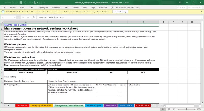
Figure 6-14 DS8000 Configuration Worksheets
Chapter 8, “Configuration flow” on page 225 explains the configuration flow in more detail.
Those settings can be changed afterward by using the Service Management Console WUI or DS GUI.
Configuring the Management Console Network
In the Service Console (WUI), select HMC Management → Change Network Settings → LAN Adapters, select the adapter, and then select Details, as shown in Figure 6-15.
|
Note: Only the customer management network interfaces eth2 and eth1 are shown and can be configured in the Network Settings dialog because the internal private black and gray networks with interfaces eth0 and eth3 are used for the running system. The eth0 and eth3 interfaces can be changed only by opening an IBM support request.
|
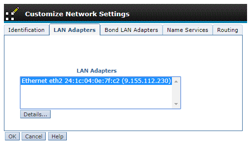
Figure 6-15 Management Ethernet settings
6.4.1 Private networks
The internal private networks (black and gray) are using the IP ranges 172.x.x.x by default. You must ensure that the network that is used for the internal private network is not interfering with outside network ranges that are used by any network that the MC can reach.
If the default address range cannot be used because it conflicts with another network, you can instead specify one of three optional addresses ranges. Table 6-3 shows the possible options that can be chosen during installation.
Table 6-3 Private networks
|
Setting
|
Black network (MC eht0)
|
Gray network (MC eth3)
|
|
Default
|
172.16.0.0. - 172.16.255.255
|
172.17.0.0 - 172.17.255.255
|
|
Option 1
|
10.235.0.0 - 10.235.2.255
|
10.236.0.0 - 10.236.2.255
|
|
Option 2
|
192.168.160.0 - 192.168.162.255
|
192.168.240.0 - 192.168.242.255
|
|
Option 3
|
9.15.0.0 - 9.15.2.255
|
9.16.0.0 - 9.16.2.255
|
When you change the internal private network, you do not need to configure each individual network interface. Instead, each change that you make changes both the black and gray networks at once.

Figure 6-16 Setting the private network range
|
Note: Changing the internal private network range on the storage system facility can be done in concurrent mode, but requires special care. For that reason, an IBM service request must be opened before making such a change.
|
6.5 User management
The Service Management GUI uses credentials that are separate from the Storage Management GUI and DS CLI. This section describes user management for the DS GUI and DS CLI first. User management of the Service Management Console is described in 6.5.3, “Service Management Console User Management” on page 189.
To manage the DS GUI and DS CLI credentials, you can use the DS CLI or the DS GUI. An administrator user ID is preconfigured during the installation of the DS8900F and this user ID uses the following defaults:
•User ID: admin
•Password: admin
The password of the admin user ID must be changed before it can be used. The GUI forces you to change the password when you first log in. By using the DS CLI, you log in but you cannot run any other commands until you change the password. For example, to change the admin user’s password to passw0rd, run the following DS CLI command:
chuser -pw passw0rd admin
After you issue that command, you can run other commands.
6.5.1 Password policies
DS8900F supports different role-based users. For more information about user and role management, see 8.2, “User and role management” on page 226. When the administrator adds a user, the administrator enters a password. During the user’s first login, this password must be changed. Password settings include the period (in days) after which passwords expire and a number that identifies how many failed logins are allowed. The user ID is deactivated if an invalid password is entered more times than the limit. Only a user with administrator rights can then reset the user ID with a new initial password.
|
Recommendation: Do not set the value of the chpass command to 0 because this setting indicates that passwords never expire and unlimited login attempts are allowed.
|
If access is denied for the admin user, for example, because of the number of invalid login attempts, the administrator can use the security recovery utility tool on the MC to reset the password to the default value. The detailed procedure is described by selecting Help Contents and can be accessed from the DS GUI.
|
Important: Upgrading an existing storage system to the latest code release does not change the old default user-acquired rules. Existing default values are retained to prevent disruption. The user might opt to use the new defaults by running the chpass -reset command. The command resets all default values to the new defaults immediately.
|
The password for each user account is forced to adhere to the following rules:
•Passwords must contain one character from at least two groups of the following ones: alphabetic, numeric, and punctuation.
•The range for minimum password length is 6 - 64 characters. The default minimum password length is 8 characters.
•Passwords cannot contain the user’s ID.
•Passwords are case-sensitive.
•The length of the password is determined by the administrator.
•Initial passwords on new user accounts are expired.
•Passwords that are reset by an administrator are expired.
•Users must change expired passwords at the next logon.
The following password security implementations are included:
•Password rules are checked when passwords are changed.
•The valid character set, embedded user ID, age, length, and history are also checked.
•Passwords that are invalidated by a change remain usable until the next password change.
•Users with invalidated passwords are not automatically disconnected from the DS8900F.
•The following password rules are checked when a user logs on:
– Password expiration, locked-out user, and failed attempts are checked.
– Users with passwords that expire or that are locked out by the administrator while they are logged on are not automatically disconnected from the DS8900F.
6.5.2 Remote authentication
You can enable and configure remote authentication to connect to an LDAP repository.
Starting with Release 9.1 the remote authentication setup can be found in the Storage Manager GUI. Go to the Access menu and select Remote Authentication. From there, click Configure Remote Authentication. The installation is guided by the Remote Authentication wizard.
DS8900F now has native support for Remote Authentication through LDAP, although it is still supported to use IBM Copy Services Manager servers as a proxy to the remote authentication servers.
Figure 6-17 shows the window that opens directly after the Welcome window. After you complete all the wizard steps of the wizard, the DS8000 is enabled and configured for remote authentication.

Figure 6-17 Remote Authentication wizard
The following prerequisites are required to complete the Remote Authentication wizard:
•Access to create users and groups on your remote authentication server.
•A primary LDAP repository URI is required.
•A secondary LDAP repository URI is optional.
•A User search base (only for Direct LDAP).
•A truststore file with a password is required (only for IBM Copy Services Manager).
•An IBM WebSphere® username with a password is required (only for IBM Copy Services Manager).
For more information about LDAP-based authentication and configuration, see LDAP Authentication for IBM DS8000 Systems: Updated for DS8000 Release 9.1, REDP-5460.
6.5.3 Service Management Console User Management
Access to the Service Management Console is managed through the HMC WUI. With the HMC, you can manage users, user roles, and authentication methods. Creating personal IDs enables individual accountability. The HMC also supports remote authentication and centralized user ID and password control through LDAP.
In the HMC Management section of the WUI, two options are available:
•Managed User Profiles and Access
•Configure LDAP
Figure 6-18 shows the two options.
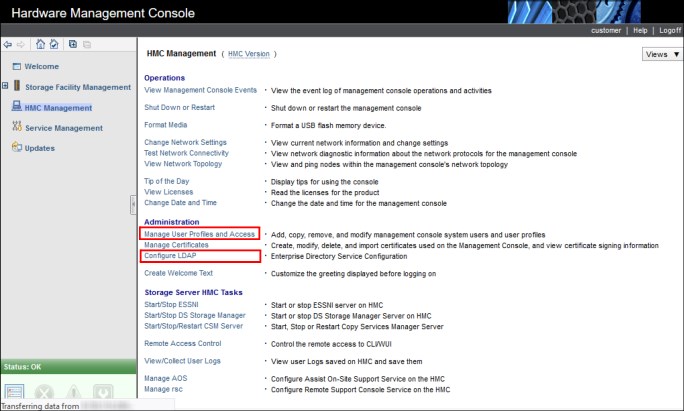
Figure 6-18 Administration options
When logged in as an admin user, you can:
•Create user IDs for predefined roles, including Service and Engineering roles.
•Modify or remove any user, including predefined Service and Engineering user IDs.
•Allow each user to change their password.
•Allow the Service and Engineering user IDs to connect remotely.
•Configure authentication locally or by using LDAP.
|
Important: Do not delete the last user ID in a role. For more information about removing user IDs for a role, see Table 6-5 on page 191.
|
There are three predefined user roles that are related to the Customer, Service, and Engineering user IDs, as shown in Table 6-4.
Table 6-4 Predefined user roles
|
Predefined user role
|
Access requirement
|
|
esshmccustomer
|
Requires a password for access regardless of authentication method.
|
|
esshmcserv
|
Local access only. Requires an IBM Support Representative to be at the HMC.
|
|
esshmcpe
|
Requires the IBM proprietary challenge/response key for remote access.
|
The roles, access, and properties for each user ID are described in Table 6-5 on page 191.
Table 6-5 User roles
|
Role
|
esshmccustomer
|
esshmcserv
|
esshmcpe
|
|
Access
|
Administration
|
Service (CE /
IBM SSR) |
Service (IBM Remote Support Center (RSC) and
IBM SSR) |
|
Default user ID
|
customer
|
IBM use only
|
IBM use only
|
|
Default Password
|
cust0mer
|
IBM use only
|
IBM use only
|
|
Remove last user in this role
|
No
|
Yes1
|
Yes2
|
|
Backup and restore in the event of HMC rebuild
|
Yes
|
Yes
|
Yes
|
|
LDAP Authentication
|
Yes
|
Yesc
|
Yes3
|
1 If removed, IBM service personnel cannot perform service functions.
2 Removing this user ID prevents remote access for support services. This user ID should not be modified or deleted.
3 This user ID can log in to this account only by using the IBM proprietary challenge/response process. Extra user IDs with this role do not use the challenge/response process and are not viable for support services.
Manage User Profile and Access windows
To manage user profiles, complete the following steps:
1. Log in to the web UI, as explained in 6.2.6, “Web User Interface” on page 180.

Figure 6-19 Manage User Profiles and Access
A new window opens that lists the user IDs and profiles for the defined console users, as shown in Figure 6-20.

Figure 6-20 Predefined User Profiles
User IDs PE, CE, and customer are specifically for DS8900F use. Ignore the other profiles.
|
Note: Do not change the user ID PE because it uses the remote challenge/response login process, which is logged and audited.
The user ID root cannot log in to the WUI. The user ID hscroot cannot access HMC functions externally. Do not use them.
Do not create user IDs with a Task Role beginning with “hmc”.
Do not create user IDs with a Task Role of esshmcoperator.
|
Adding a user ID
To add a user ID, complete the following steps:

Figure 6-21 User Profiles option menu

Figure 6-22 Add User window
Only those roles that are outlined by the boxes are valid Task Roles.
3. Complete the following fields:
a. Under Description, define a user or use HMC User as an example.
b. Passwords must adhere to the DS8900F password policies. For more information, see , “After you issue that command, you can run other commands.” on page 187.
c. Choose the type of Authentication that you want.
d. Select AllSystemResources, under Managed Resource Roles.
e. Select the Task Role type.
4. Click User Properties to optionally add Timeout and Inactivity values. Ensure that Allow access via the web is selected if web access is needed.
Figure 6-23 shows these settings.

Figure 6-23 User Properties menu
5. Click OK, and then click OK again. This task is complete.
The User Profiles are updated and list the new user ID. As an example, user ID IBM_RSC was created and is shown in Figure 6-24 and Figure 6-25 on page 195.

Figure 6-24 IBM_RSC user ID

Figure 6-25 IBM_RSC user ID properties
6.5.4 Service Management Console LDAP authentication
Before LDAP authentication is selected, the HMC must first be configured to access an LDAP server. Complete the following steps:

Figure 6-26 Configuring LDAP
2. The window that is shown in Figure 6-27 opens. Perform the following actions:
a. Select the Enable LDAP box.
b. Provide the Primary URI, and optionally, the Backup URI.
c. Choose either TLS Encryption or Non-Anonymous Binding.
d. Select an attribute for Use the Following Attribute for User Login.
e. Identify the Distinguished Name Tree for search functions.
f. Do not select Enable LDAP for Remote User Management.
3. Click OK to complete this task.
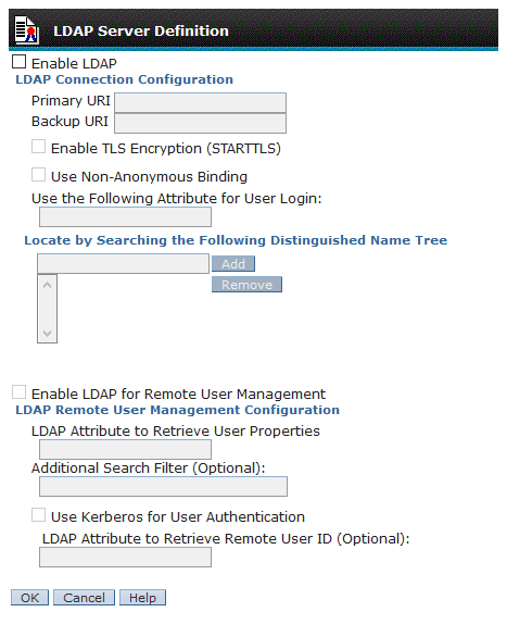
Figure 6-27 LDAP Server Definition window
6.6 Secondary Management Console
The secondary MC is used for redundancy and it is part of the DS8900F ME. The primary MC is referred to as MC1, and the secondary MC is referred to as MC2. The two MCs run in a dual-active configuration, so either MC can be used at any time. Each MC is assigned a role of either primary (normally MC1) or secondary (normally MC2). Certain service functions can be performed only on the primary MC.
The DS8900F can run all storage duties while the MC is down or offline, but configuration, error reporting, and maintenance capabilities become severely restricted. Any organization with high availability (HA) requirements should strongly consider deploying an MC redundant configuration.
|
Important: The primary and secondary MCs are not available to be used as general-purpose computing resources.
|
6.6.1 Management Console redundancy benefits
MC redundancy provides the following advantages:
•Enhanced maintenance capability
Because the MC is the only interface that is available for service personnel, an alternative MC provides maintenance operational capabilities if the internal MC fails.
•Greater availability for power management
Using the MC is the only way to safely power on or power off the DS8900F. The secondary MC is necessary to shut down the DS8900F if the primary MC fails.
•Greater availability of encryption deadlock recovery
If the DS8900F is configured for Full Disk Encryption (FDE) and an encryption deadlock situation occurs, the use of the MC is the only way to input a recovery key to allow the DS8900F to become operational.
•Greater availability for Advanced CS
Because all CS functions are driven by the MC, any environment that uses Advanced CS must include dual MCs for operational continuity.
•Greater availability for configuration operations
All configuration commands must go through the MC. This requirement is true regardless of whether access is through IBM Spectrum Control, DS CLI, or DS GUI. The secondary MC allows these operations to continue if the primary MC fails.
When a configuration or CS command is run, the DS CLI or DS GUI sends the command to the first MC. If the first MC is unavailable, it automatically sends the command to the second MC instead. Typically, you do not need to reissue the command.
Any changes that are made by using one MC are instantly reflected in the other MC. No host data is cached within the MC, so no cache coherency issues occur.
..................Content has been hidden....................
You can't read the all page of ebook, please click here login for view all page.