
Day 11 It’s an Analog World
The Plan
We live in an analog world. Temperature, humidity, and pressure but also voltages and currents are analog. If we want our embedded-control applications to interact with the outside world, we need to learn to interpret analog information and convert it to digital so that a microcontroller can elaborate it and possibly produce an analog output again. The analog-to-digital converter module is one of the key interfaces to the “real” world. The PIC32MX family was designed with embedded-control applications in mind and therefore is ideally prepared to deal with the analog nature of this world. A fast analog-to-digital converter (ADC), capable of 500,000 conversions per second, is available on all models with an input multiplexer that allows you to monitor a number of analog inputs quickly and with high resolution. In this lesson we will learn how to use the 10-bit ADC module available on the PIC32MX family to perform two simple measurements on the Explorer 16 board: reading a voltage input from a potentiometer first and a voltage input from a temperature sensor later.
Preparation
In addition to the usual software tools, including the MPLAB® IDE, the MPLAB C32 compiler, and the MPLAB SIM simulator, this lesson will require the use of the Explorer 16 demonstration board and the In-Circuit Debugger of your choice.
The Exploration
The first step in using the ADC, like any other peripheral module inside the PIC32, is to familiarize yourself with the module building blocks and the key control registers.
Yes, this means reading the datasheet once more, and even the Explorer 16 User Guide, to find out the schematics.
We can start by looking at the ADC module block diagram (see Figure 11.1 ).
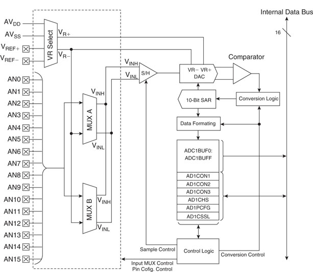
This is a pretty sophisticated structure that offers many interesting capabilities:
All these capabilities require a number of control registers to be properly configured, and I understand how, especially at the beginning, the number of options available and decisions to take could make you a bit dizzy. So we will start by taking the shortest and simplest approach with the simplest example application: reading the position of the R6 potentiometer on the Explorer 16 board.
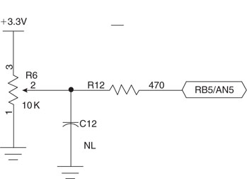
The 10 k Ohm potentiometer is directly connected to the power supply rails so that its output can span the entire range of values from 3.3 V to the ground reference. It is connected to the RB5 pin that corresponds to the analog input AN5 of the ADC input multiplexer.
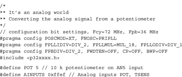
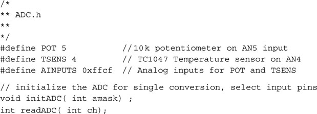
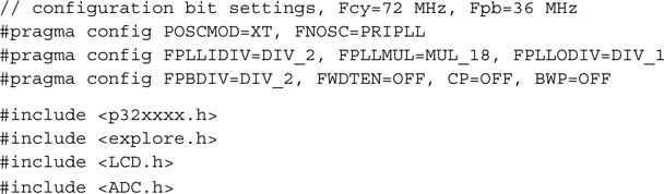
After creating a new project using the appropriate checklist, we can create a new source file pot.c, including the usual header file and adding the definition of a couple useful constants. The first one, POT, defines the input channel assigned to the potentiometer; the second one, AINPUTS, is a mask that will help us define which inputs should be treated as analog and which ones as digital:
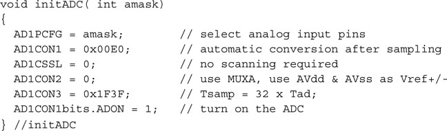
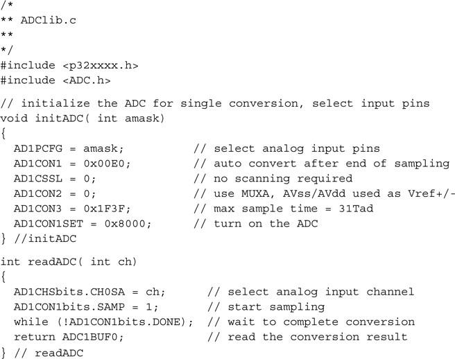
The actual initialization of all the ADC control registers can be best performed by a short function, initADC(), that will produce the desired initial configuration:
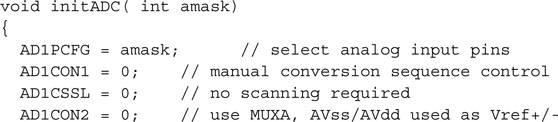
By keeping amask as a parameter to the initialization routine, we make it flexible so it’s able to accept different (multiple) input channels in future applications.
Note
As for all other peripheral modules found inside the PIC32, a corresponding peripheral library (adc.h) offers a set of functions and macros that are supposed to simplify or at least make the code that accesses the ADC module more readable. Because of the great flexibility of the ADC module, it is my very personal opinion that it is best if you familiarize yourself first with the low-level details of its operation by directly accessing the few control registers rather than seeking early refuge in the peripheral library.
The First Conversion
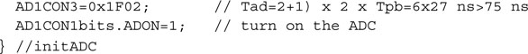
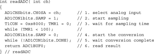
The actual analog-to-digital conversion is a two-step process. First we need to take a sample of the input voltage signal; then we can disconnect the input and perform the actual conversion of the sampled voltage to a digital value. The two distinct phases are controlled by two separate control bits in the AD1CON1 register: SAMP and DONE. The timing of the two phases is important to provide the necessary accuracy of the measurement:
Here is a basic conversion routine:
Automating Sampling Timing
As you can see, using this basic method, we have been responsible for providing the exact timing of the sampling phase, dedicating a timer to this task and performing two waiting loops. But on the PIC32 ADC module, the sampling phase can be self-timed up to a maximum of 32 × Tad periods. Whether we can use this feature or not will depend ultimately on the product of the source impedance and the ADC input capacitance. By setting the SSRC bits in the AD1CON1 register to the 0x7 configuration, we can enable an automatic start of conversion upon termination of the self-timed sampling period. The sampling period itself is selected by the AD1CON3 register SAM bits. Here is a new and improved example that uses the self-timed sampling and conversion trigger:
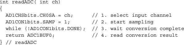
Notice how making the conversion-start, triggered automatically by the completion of the self-timed sampling phase, gives us two advantages:
With the ADC so configured, starting a conversion and reading the output is a trivial matter:
Developing a Demo
All that remains to do at this point is to figure out an entertaining way to put the converted value to use on the Explorer 16 demo board. The LEDs connected to PORTA are an intriguing choice, but those of you using a PIC32 Starter Kit would not be able to enjoy the experience, since most of the PORTA pins would be tied up by the JTAG port. Instead we will use the LCD library developed in the previous chapter to display a blocky bar graph. Yes, we could use the nice and smooth progress bar developed in the previous chapter (Day 10) but I don’t want you to get distracted by the details. Here is the main routine we will use to test our analog-to-digital conversion functions:
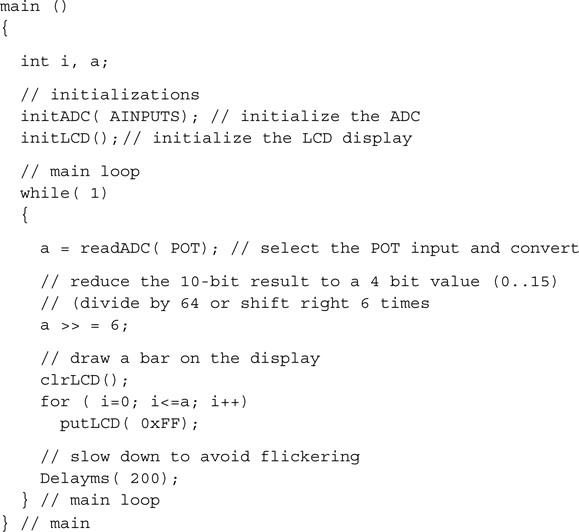
After the call to the ADC initialization routine, we can initialize the LCD display module. Then in the main loop we perform the conversion on AN5 and we reformat the output to fit our special display requirements. As configured, the 10-bit conversion output will be returned as a right-aligned integer in a range of values between 0 and 1023. By dividing that value by 64 (or, in other words, shifting it right six times) we can reduce the range to a 0 to 15 value. Printing the resulting number of “bricks” gives a blocky bar whose length is proportional to the position of the potentiometer.
Remember to add an #include < > statement for the LCD.h library and add to the project source files list both the explore.c and LCDlib.c modules we placed in the lib directory.
Build the project and, following the usual In Circuit Debugging checklist, program the Explorer 16 board. If all goes well, you will be able to play with the potentiometer, moving it from side to side while observing a bar of 16 blocks moving from left to right correspondingly.
Creating Our Own Mini ADC Library
We will use over and over the two simple routines that initialize the ADC module and perform a single self-timed conversion. Let’s separate them into a standalone small library called ADClib.c that we will add to our new collection inside the lib directory.
Similarly we can isolate the include file LCD.h that offers the basic set of definitions and prototypes required to access the library functions. We will save it in the include directory.
Simple enough. We are ready to proceed with more fun and games!
Fun and Games
Okay, I’ll admit it, the previous project was not too exciting. After all, we have been using a 32-bit machine operating at 72 MHz, capable of performing a 10-bit analog-to-digital conversion several hundred thousands of times per second, only to discard all but 4 bits of the conversion result and watch a blocky bar moving on an LCD display. How about making it a bit more challenging and playful instead? How about developing a monodimensional Pac-Man game, or should we call it the “Pot-Man” game?
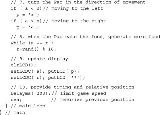
If you remember the old Pac-Man game—please don’t tell me you never heard of it, but if you really have to, check the link to a Wikipedia entry at the end of this chapter—there is a hungry little “thing,” the Pac, that roams a two-dimensional labyrinth in a desperate search for food. Now, with a little fantasy, we can imagine a monodimensional reduction of the game, where the Pac is represented by a single < or > character, depending on the direction of movement. It is limited to a left/right movement on a line of the LCD display as it is controlled by the potentiometer position. Bits of food are represented by a * character and are placed randomly, one at a time, on the same line. As soon as the Pac reaches a piece of food, it gulps it and moves on, and a new piece is placed in a different location.
Once more, the pseudo-random number generator function rand() (defined in stdlib.h) will be very helpful here. All games need a certain degree of unpredictability, and pseudo-random number generators are the way computer games provide it in a world of logic and otherwise infinite repetition.
We can start by modifying the previous project code or typing away from scratch a brand-new Pot-Man.c file. A new project needs to be created, and I suggest we call it simply POT. Just a few more lines of code are truly needed to perform the simple animation:
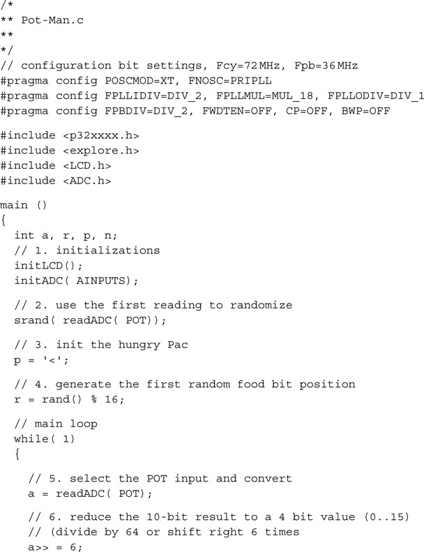
Don’t forget to include in the project the LCDlib.c, ADClib.c, and Explore.c files found in the lib directory. Build the project and program it onto the Explorer 16 board. You will have to admit it: Analog-to-digital conversions are so much more entertaining now!
Sensing Temperature
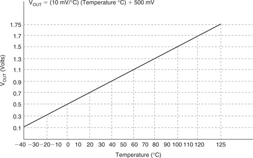
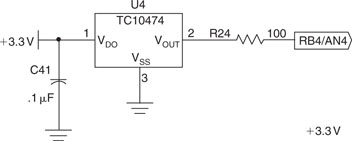
Moving on to more serious things, there is a temperature sensor mounted on the Explorer 16 board, and it happens to be a Microchip TC1047A integrated temperature-sensing device with a nice linear voltage output. This device is very small, it is offered in a SOT-23 (three-pin, surface-mount) package. The power consumption is limited to 35uA (typ.) while the power supply can cover the entire range from 2.5 V to 5.5 V. The output voltage is independent from the power supply and is an extremely linear function of the temperature (typically within 0.5 degree C) with a slope of exactly 10mV/C. The offset is adjusted to provide an absolute temperature indication according to the formula shown in Figure 11.3.
We can apply our newly acquired abilities to convert the voltage output to digital information using, once more, the ADC of the PIC32. The temperature sensor is directly connected to the AN4 analog input channel as per the Explorer 16 board schematic (see Figure 11.4 ).
We can reuse the ADC library developed for the previous exercise and put it in a new project called TEMP, saving the previous source file as Temp.c.
Let’s start modifying the code to include a new constant definition: TSENS for the ADC input channel assigned to the temperature sensor.
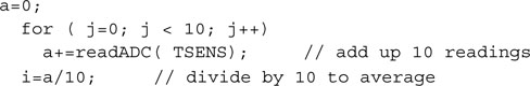
As you can see, nothing else needed to change with regard to the ADC configuration or activation of the conversion sequence. Presenting the result on the LCD display might be a little tricky, though. Temperature sensors provide a certain level of noise, and to give a more stable reading it is common to perform a little filtering. Taking groups of 10 samples over a period of a second, for example, and performing an average will give us a cleaner value to work with.
Referring to the formula in Figure 11.3, we can now calculate the absolute temperature value as measured by the TC1047 on the Explorer 16 board. In fact, resolving for the temperature in degrees C, we obtain:
![]()
where:
![]()
Since we have configured the PIC32 ADC module to use as an internal voltage reference the AVdd line connected to Vdd (3.3 V), and knowing it operates as a 10-bit, we derive that the ADC resolution is 3.3 mV/bit. Hence the temperature can be expressed as:
![]()
We could easily print the resulting absolute temperature on the LCD display, but it would not be fun, would it? How about providing instead a relative temperature indication using a single character (cursor) position as an index, or even better, how about using the temperature as a way to control the monodimensional Pac-Man game we developed in the previous project? We could heat the sensor by breathing hot air onto the sensor to move it to the right or blowing cold air on it to move it to left.
From a practical point of view, it seems easy to implement. We can sample the initial temperature value just before the main loop and then use it as a reference to determine an offset for the Pac position relative to the center of the display. In the main loop we will update the cursor position, moving it to the right as the sensed temperature increases or to the left as the sensed temperature decreases. Here is the complete code for the new Temp-Man game, or should we call it the Breathalyzer game instead?
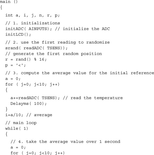
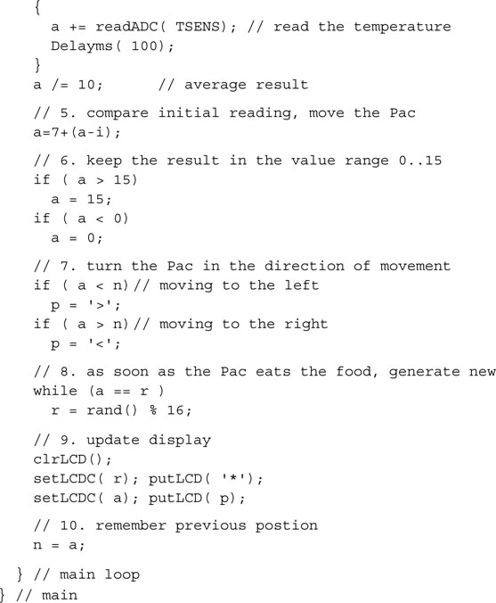
You will notice how most of the code has remained absolutely identical to our previous project/game. The only notable differences are found in the following sections:
Build the project with the usual checklists, remembering to include all the libraries required. Program it to the Explorer 16 board using the In-Circuit debugger of choice and give it a try.
The first problem you will encounter will be to identify the minuscule temperature sensor on the board. (Hint: It is close to the lower-left corner of the processor module and it looks just like any surface-mount transistor). The second immediate problem will be to find the right way to breathe on the board to produce warm or cold air as required to move the Pac. It is more complex than it might appear. In fact, personally, I found the cooling part to be the hardest; some friends are suggesting that this might be a problem related to my current position. If you work in marketing, they say, it’s just hot air!
Debriefing
In this lesson we have just started scratching the surface and exploring the possibilities provided by the ADC module of the PIC32. We have used one simple configuration of the many possible and only a few of the advanced features available. We have tested our newly acquired capabilities with two types of analog input available on the Explorer 16 board, and hopefully we had some fun in the process.
Notes for the PIC24 Experts
The ADC module of the PIC32 is mostly identical to the PIC24 peripheral, yet some important enhancements have been included in its design. Here are the major differences that will affect your code while porting an application to the PIC32:
Tips & Tricks
If the sampling time required is longer than the maximum available option (32×Tad), you can try to extend Tad first or, a better option, swap things around and enable the automatic sampling start (at the end of the conversion). This way the sampling circuit is always open, charging, whenever the conversion is not occurring. Manually clearing the SAMP bit will trigger the actual conversion start. Further, having Timer3 periodically clearing the SAMP control bit for you (one of the options for the SSRC bits in AD1CON1) and enabling the ADC end of conversion interrupt will provide the widest choice of sampling periods possible for the least amount of MCU overhead possible. No waiting loops, only a periodic interrupt when the results are available and ready to be fetched.
Further, not all applications require a complete conversion of analog input values. The PIC32MX family offers also analog comparator modules (two), with dedicated input multiplexers. They can assist in those applications in which we need a fast response to an analog input as it crosses a threshold. No need to set up the ADC, select a channel, and perform a conversion; the comparison is done continuously. An interrupt (or an output signal) is produced immediately as the reference voltage is reached.
Speaking of reference voltages, yet another module, called the Comparator Reference, effectively representing a small digital-to-analog converter of sorts, can generate up to 32 reference voltages to be used with the comparator modules or independently.
Exercises
Books
Baker, Bonnie, A Baker’s Dozen: Real Analog Solutions for Digital Designers (Newnes, Burlington, MA). For proper care and feeding of an analog-to-digital converter, look no further than this cookbook.
Links
www.microchip.com/filterlab. Download the free FilterLab software from the Microchip Web site; it will help you quickly and efficiently design antialiasing filters for your analog inputs.
www.microchip.com/stellent/idcplg?IdcService=SS_GET_PAGE&nodeId=2102¶m=en021419&pageId=79&pageId=79. Temperature sensors are available in many flavors and a choice of interface options, including direct I2C or SPI digital output.