
Day 12 Capturing User Inputs
The Plan
If analog inputs are the essence of the interface between an embedded-control application and the outside world, digital inputs are, sadly, the true foundation of the user interface. As wrong as this might seem, for a long time now we humans have been trained to reduce our interaction with them, the machines, to buttons and switches. Probably this is because the alternative, using speech, gestures, and vision, requires such a leap in the complexity of the interface that we have rather learned to accept the limitation and reduced ourselves to communicate essentially through ones and zeros. Perhaps this explains the attention and enthusiasm that some recent innovations are producing as pioneered by video games and mobile phone manufacturers; think of the Wii accelerometer-filled wand and the iPhone multitouch sensing screen, for example.
Today we will explore various methods to capture “traditional” user inputs by detecting the activation of buttons and simple mechanical switches, reading the inputs from rotary encoders, and eventually interfacing to computer keyboards. This will give us the motivation to investigate a few alternative methods and evaluate their trade-offs. We’ll implement software state machines, practice using interrupts, and possibly learn to use a few new peripherals. It’s going to be a long day, so be rested and ready to start at dawn!
Preparation
In addition to the usual software tools, including the MPLAB® IDE, the MPLAB C32 compiler, and the MPLAB SIM simulator, this lesson will require the use of the Explorer 16 demonstration board and an In-Circuit Debugger of your choice. You will also need a soldering iron and a few components ready at hand to expand the board capabilities using the prototyping area or a small expansion board. You can check on the companion Web site (www.exploringPIC32.com) for the availability of expansion boards that will help you with the experiments.
Buttons and Mechanical Switches
Reading the input from a button, a mechanical switch, is one of the most common activities for an embedded-control application. After all, a single bit of information needs to be retrieved from a port pin configured as a digital input. But the great speed of a microcontroller and the mechanical (elastic) properties of the switch require that we pay some attention to the problem.
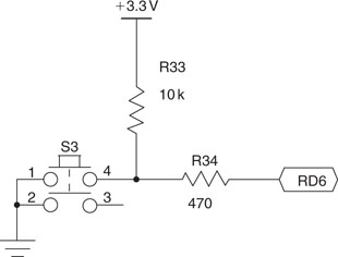
In Figure 12.1 you can see the connection of one of the four buttons present on the Explorer 16 demonstration board. At idle, the switch offers an open circuit and the input pin is kept at a logic high level by a pull-up resistor. When the button is pressed, the contact is closed and the input pin is brought to a logic low level. If we could consider the switch as an ideal component, the transition between the two states would be immediate and unambiguous, but the reality is a little different. As represented in Figure 12.2, when the button is pressed and the mechanical contact is established, we obtain all but a clean transition. The elasticity of the materials, the surface oxidation of the contacts, and a number of other factors make it so that there can be a whole series of transitions, increasing in number and spaced with the aging and general wear of the device. This phenomenon, generally referred to as contact bouncing, can continue in the worst cases for several hundred microseconds if not for milliseconds.
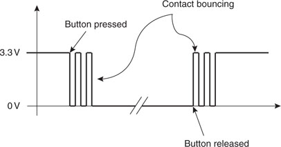
When the button is released, a similar bouncing effect can be detected as the pressure between the two contact surfaces is removed and the circuit is opened.
For a PIC32 operating at a high clock frequency, the timescale of the event is enormous. A tight loop polling the status of the input line could detect each and every bounce and count them as numerous distinct activations and releases of the button. In fact, as a first experiment, we could devise a short piece of code to do just that so we can access the “quality” of the buttons available on the Explorer 16 board.
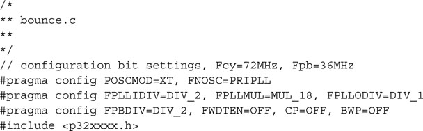
Let’s create a new project called Buttons, and let’s add a first new source file to it that we’ll call bounce.c:
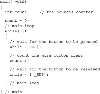
After initializing an integer counter, we directly enter the main loop, where we wait for the leftmost button on the board (marked S3 and connected to the RD6 input pin) to be pressed (transition to logic level low). As soon as we detect the button pressure, we increment the counter and proceed to the next loop, where we wait for the button to be released, only to continue in the main loop and start from the top.
Build the project immediately and program the code on the Explorer 16 board using your in circuit debugger of choice. To perform our first experiment, you can now run the code and slowly press the S3 button for a predetermined number of times: let’s say 20! Stop the execution and inspect the current value of the variable count. You can simply move your mouse over the variable in the editor window to see a small popup message appear (if the MPLAB option is enabled), or you can open the Watch window and add the variable count to it. (I suggest you set its visualization properties to Decimal.)
In my personal experimentation, after 20 button pushes I obtained a value of count varying generally between 21 and 25. As car manufacturers say: “Your mileage might vary” ! This is actually a very good result, indicating that most of the time there have been no bounces at all. It’s a testament to good-quality contacts, but it also reflects the fact that the board button has been used very little so far. If we are to design applications that use buttons and mechanical switches, we have to plan for the worst and consider a substantial degradation of performance over the life of the product.
Button Input Packing
Planning for a general solution to apply to all four buttons available on the Explorer 16 and extensible to an entire array of similar buttons if necessary, we will start developing a simple function that will collect all the inputs and present them conveniently encoded in a single integer code. Save the previous source file (Save As) with the new name Buttons.c and add it to the project (replacing bounce.c):
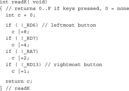
In fact, the designers of the of the Explorer 16 board have “fragmented” the input pins, corresponding to the four buttons, between two ports in noncontiguous positions, probably in an attempt to ease the board layout rather than to please us, the software developers.
The function readK() as proposed collects the four inputs and packs them contiguously in a single integer returned as the function value. Figure 12.3 illustrates the resulting encoding.
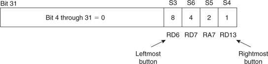
The position of the buttons is now reflected in the relative position of each bit in the function return value, with the MSb (bit 3) corresponding to the leftmost button status. Also, the logic of each input is inverted so that a pressed button is represented by a 1. As a result, when called in the idle condition, no button pressed, the function returns 0, and when all the buttons are pressed, the function returns a value 0x0f.
Notice that we have performed no debouncing yet. All readK() does is grab a picture of the status of the inputs and present them in a different convenient format. Should we have a matrix of buttons arranged in a 3 × 4, 4 × 4, or larger keypad, it would be easy to modify the function while maintaining the output format and leaving untouched the rest of the code we will develop from here.
We can quickly modify the main() function to visualize the output on the LCD display using the LCD.h library we developed in the previous chapters:
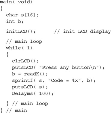
Build the project after adding the LCDlib.c module to the list of the project sources and program the Explorer 16 board with your In-Circuit Debugger of choice.
As you run the simple demo, you will see that as soon as a button is pressed, a new code is immediately displayed. Multiple buttons can be pressed simultaneously, producing all possible codes from 0x01 to 0x0f.
For our convenience, we will add the readK() function to our explore.c library module. In fact, if you are working with the code provided with the CD-ROM that accompanies this book, you will notice that the function is already there but under another name, readKEY(), so as not to create any conflict with the previous and following examples.
Button Inputs Debouncing
It is time now to start working on the actual debouncing. The basic technique used to filter out the spurious commutations of the mechanical switch consists of adding a small delay after the first input commutation is detected and subsequently verifying that the output has reached a stable condition. When the button is released, a new short delay is inserted before verifying once more that the output has reached the idle condition.
Here is the code for the new function getK() that performs the four steps listed previously and some more:
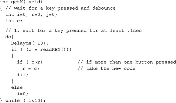
In 1, we have a do .. while loop that, at regular intervals 10ms apart, uses the function readKEY() to check on the inputs status. The loop is designed to terminate only after 10 iterations (for a total of 100 ms) during which there has been no bouncing. During that time, though, the user might have pressed more buttons. The function accommodates for one or more buttons to be “added” over time rather than assuming they will all be pressed together with absolute synchronicity. The variable r will contain the “most complete” button code.
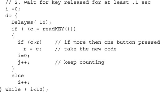
In 2, the situation is reversed as buttons are released. The do.. while is designed to wait for all buttons to be released until the inputs stabilize in the idle condition for at least 100 ms.
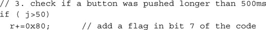
In 3, we are actually making use of an additional counter represented by the variable j that had been added to the second loop. Its role is that of detecting when the button-pressed condition is prolonged beyond a certain threshold. In this case it’s set to 500ms. When this happens, an additional flag (bit 7) is added to the return code. This can be handy to provide additional functionalities to an interface without adding more hardware (buttons) to the Explorer 16 board. So, for example, pressing the leftmost button for a short amount of time produces the code 0x08. Pressing the same button for more than half a second will return the code 0x88 instead.
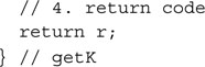
It is only in 4 that the button code encoded in the variable r is returned to the calling program.
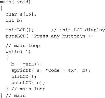
To test the new functionality and verify that we have eliminated all button bouncing, we can now replace the main() function with the following code and save the resulting file as Buttons2.c:
Remember to include the LCDlib.c and explore.c modules found in the lib directory to the project.
Replace Buttons2.c in the project source list in place of buttons.c and build the project. After programming the Explorer 16 board with your in-circuit debugger of choice, run the code and observe the results on the LCD display.
First you will notice that contrary to what happened in the previous demo, new codes are displayed only after buttons are released. The function getK() is in fact a blocking function. It waits for the user inputs and returns only when a new return code is ready.
Play with various combinations of buttons, pressing two or three of them more or less simultaneously, and observe how the order of press and release does not affect the outcome, simplifying the user input. Try long and short button combinations. You can modify the threshold or even introduce secondary thresholds for very long button presses.
Once more, because of its usefulness, I suggest we add the getK() function to our explore.c library module. If you are using the code from the CD-ROM attached to this book, you will find it already there with the name changed in getKEY() to avoid conflicts with the examples in this chapter.
Rotary Encoders
Another type of input device based on mechanical switches (sometimes replaced by optical sensors) and very common in many embedded-control applications is the rotary encoder. In the past we have seen the use of a potentiometer attached to the PIC32 ADC module to provide user input (and control the position of the Pac-Man), but rotary encoders are pure digital devices offering a higher degree of freedom. Their main advantage is that they offer no limitation to the movement in any of the rotation directions. Some encoders provide information on their absolute position; others of simpler design and lower cost, known as incremental encoders, provide only a relative indication of movement.
In embedded applications, absolute rotary encoders can be used to identify the position (angle) of a motor/actuator shaft. Incremental encoders are used to detect direction of motion and speed of motors but also for user interfaces as a rapid input tool to select an entry in a menu system on a display panel: think of the omnipresent input knob on car navigators and digital radios. Another good example of a user interface application of an incremental encoder is a (ball) mouse, assuming you can still find one nowadays. They used to contain two (optical) rotary encoders to detect relative motion in two dimensions. In fact, if you think of it, your computer has no idea “where” the mouse is at any given point in time, but it knows exactly how far you moved it and in which direction. Don’t look at modern “optical” mice, though; the technology they are based on is completely different.
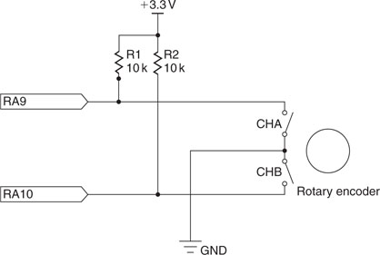
To experiment with a simple and inexpensive rotary encoder (I used an ICW model from Bourns), I suggest you test your prototyping skills by soldering only a couple of resistors (10 K Ohm) onto the Explorer 16 board prototyping area and connecting just three wires between the encoder and the PIC32 I/O pins, as illustrated in Figure 12.4.
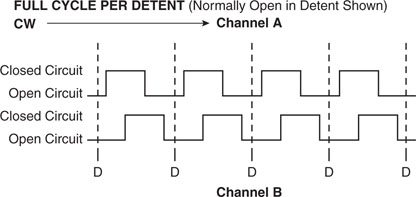
When so connected, the encoder provides two output waveforms (shown in Figure 12.5) that can be easily interpreted by the PIC32. Notice that the motion of the encoder is in steps between detent positions. At each step the encoder produces two commutations, one on each mechanical switch corresponding to an input pin. The order of the two commutations tells us about the direction of rotation. Since the two waveforms are identical but appear to be out of phase by a 90-degree angle, these simple encoders are often referred to as quadrature encoders.
At rest, both switches are open and the corresponding input pins are pulled up at a logic level high. When rotating clockwise, the CHA switch is closed first, bringing the RA9 input pin to a logic low, then the CHB switch is closed, bringing the RA10 pin to a logic low level. When rotating counter-clockwise, the sequence is inverted. As the encoder reaches the next detent position, both switches are opened again.
Here is a simple program that can be used to demonstrate how to interface to a rotary encoder to track the position of a rotating knob and display a relative counter on the LCD display:
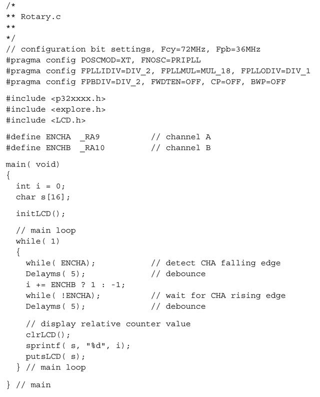
The idea behind the code in the main loop is based on a simple observation: by focusing only on one input commutations—say, ENCHA—we can detect motion. By observing the status of the second input ENCHB immediately after the activation of the first channel, we can determine the direction of movement. This can be seen in Figure 12.5 as you move your eyes from left to right (corresponding to a clockwise rotation); when the CHA switch is closed (represented as a rising edge), the CHB switch is still open (low). But if you read the same figure from right to left (corresponding to a counter-clockwise rotation of the encoder), when CHA is closed (rising edge), CHB is already closed (high).
Since we have not forgotten the lesson about switch bouncing, we have also added a pair of calls to a delay routine, to make sure that we don’t read multiple commutations when there is really just one. The length of the delays was decided based on information provided by the encoder manufacturer on the device datasheet. The ICW encoders’ contacts are in fact rated for a maximum of 5ms bounces when operated at a rotation speed of 15 RPM.
Create a new project called Rotary. Save the preceding code as rotary.c and remember to add our default include directory, as well as the LCDlib.c and explore.c source files found in the lib directory, to the list of project source files.
Build and program the Explorer 16, modified for the application, to run the short demo.
If all went well, you will see a counter displayed in decimal format being continuously updated on the LCD display as you turn the encoder knob. The counter is a signed (32-bit) integer and as such it can swing between positive and negative values, depending on how much and how long you turn clockwise and counter-clockwise.
Interrupt-Driven Rotary Encoder Input
The main problem with the simple demonstration code we have just developed is in its assumption that the entire attention of the microcontroller can be devoted to the task at hand: detecting the commutations on the CHA and CHB input pins. This is perhaps an acceptable use of resources when the application is waiting for user input and there are no other tasks that need to be handled by the microcontroller. But if there are and, as often is the case, they happen to be of higher priority and importance than our application, we cannot afford the luxury to use a blocking input algorithm. We need to make the encoder input a background task.
As we saw in Day 5, the simplest way to obtain a sort of multitasking capability in embedded-control applications is to use the PIC32 interrupt mechanisms. A background task becomes a small state machine that follows a simple set of rules. In our case, transforming the algorithm developed in the previous demonstration into a state machine and drawing its diagram (see Figure 12.6), we learn that only two states are required:
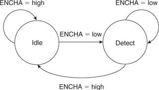
The transitions between the two states are simply expressed in Table 12.1
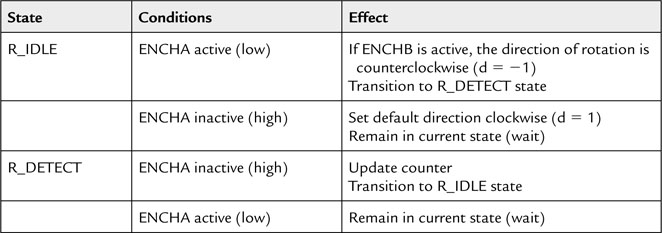
By binding the execution of the state machine to a periodic interrupt produced by one of the timers (Timer2, for example) we can ensure that the task will be performed continuously and, with the proper choice of timing, obtain a natural debouncing in the process.
We can create a new source file that we will call Rotary2.c, starting with the usual template and the following few declarations:
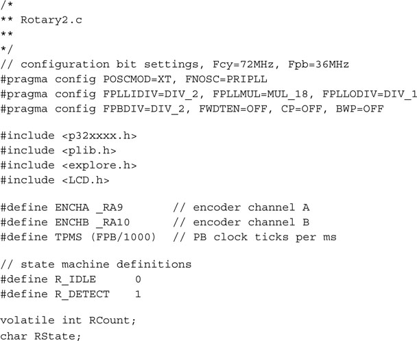
Notice that RCount, the variable used to maintain the relative movement counter, is declared as a volatile to inform the compiler that its value could change unpredictably at the hands of the interrupt service routine (state machine). This will ensure that the compiler won’t try to optimize access to it in the main() function by making wrong assumptions, since the variable is never written to in the main loop.
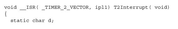
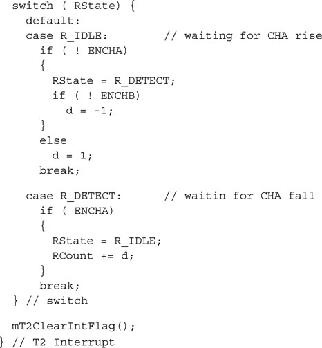
Choosing to use the vectored interrupt mechanism of the PIC32 for efficiency, we can code the interrupt service routine as follows:
Finally, a small initialization routine is necessary to set up the initial conditions required for the Timer2 peripheral (with a 5 ms period) and the state machine to operate correctly:
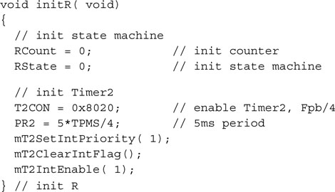
The Timer2 interrupt can be set to a level 1 priority, the lowest, since the absolute timing is not relevant here. Even when rotating the encoder very fast (120 RPM max, according to the device datasheet), the commutations are going to happen on a timescale that is an order of magnitude larger (20 ms). Any other task present in your application can, in fact, be assumed to have a higher priority.
Finally, here is a new main() function designed to put our rotary encoder routines to the test by periodically (10 times a second) checking the value of RCount and displaying its current value on the LCD display:
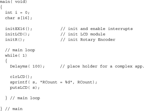
Notice the call to the initEX16() function that, if you remember from Day 10, besides performing the fine tuning of the PIC32 for performance, enables the vectored interrupt mode.
Notice also that where the Delayms( 100) call is made, in the main() function, you could actually replace the core of a complex application that will now be able to operate continuously without being “blocked” by the encoder detection routines.
Keyboards
If a few buttons, a keypad, or a rotary encoder offer the possibility to inexpensively accept user input to an embedded-control application, they pale compared to the convenience of a real computer keyboard.
With the advent of the USB bus, computers have finally been freed of a number of “legacy” interfaces that had been in use for decades, since the introduction of the first IBM PC. The PS/2 mouse and keyboard interface is one of them. The result of this transition is that a large number of the “old” keyboards are now flooding the surplus market, and even new PS/2 keyboards are selling for very low prices. This creates the opportunity to give our future PIC32 projects a powerful input capability in return for very little complexity and cost.
Note
Interfacing to a USB keyboard is a completely different deal. You will need a USB host interface, with all the hardware and software complexity that it implies. New PIC32 models with USB host peripherals will address these needs, but a discussion of their use and the command of the USB protocol required are well beyond the scope of this book.
PS/2 Physical Interface
The PS/2 interface uses a five-pin DIN (see Figure 12.7) or a six-pin mini-DIN connector. The first was common on the original IBM PC-XT and AT series but has not been in use for a while. The smaller six-pin version has been more common in recent years. Once the different pin-outs are taken into consideration, you will notice that the two are electrically identical.
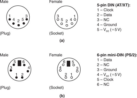
The host must provide a 5 V power supply. The current consumption will vary with the keyboard model and year, but you can expect values between 50 and 100 mA. (The original specifications used to call for up to 275 mA max.)
The data and clock lines are both open-collector with pull-up resistors (1–10 k ohm) to allow for two-way communication. In the normal mode of operation, it is the keyboard that drives both lines to send data to the personal computer. When it is necessary, though, the computer can take control to configure the keyboard and to change the status LEDs (Caps Lock and Num Lock).
The PS/2 Communication Protocol
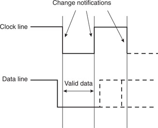
At idle, both the data and clock lines are held high by the pull-ups (located inside the keyboard). In this condition the keyboard is enabled and can start sending data as soon as a key has been pressed. If the host holds the clock line low for more than 100 us, any further keyboard transmissions are suspended. If the host holds the data line low and then releases the clock line, this is interpreted as a request to send a command (see Figure 12.8).
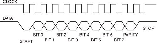
The protocol is a curious mix of synchronous and asynchronous communication protocols we have seen in previous chapters. It is synchronous since a clock line is provided, but it is similar to an asynchronous protocol because a start, a stop, and a parity bit are used to bracket the actual 8-bit data packet. Unfortunately, the baud rate used is not a standard value and can change from unit to unit over time, with temperature and the phase of the moon. In fact, typical values range from 10 to 16 kbits per second. Data changes during the clock high state. Data is valid when the clock line is low. Whether data is flowing from the host to the keyboard or vice versa, it is the keyboard that always generates the clock signal.
Note
The USB bus reverses the roles as it makes each peripheral a synchronous slave of the host. This simplifies things enormously for a non real-time, nonpreemptive multitasking operating system like Windows. The serial port and the parallel port were similarly asynchronous interfaces and, probably for the same reason, both became legacy with the introduction of the USB bus specification.
Interfacing the PIC32 to the PS/2
The unique peculiarities of the protocol make interfacing to a PS/2 keyboard an interesting challenge, since neither the PIC32 SPI interface nor the UART interface can be used. In fact, the SPI interface does not accept 11-bit words (8-bit or 16-bit words are the closest options), whereas the PIC32 UART requires the periodic transmission of special break characters to make use of the powerful auto baud-rate detection capabilities. Also notice that the PS/2 protocol is based on 5 V level signals. This requires care in choosing which pins can be directly connected to the PIC32. In fact, only the 5 V-tolerant digital input pins can be used, which excludes the I/O pins that are multiplexed with the ADC input multiplexer.
Input Capture
The first idea that comes to mind is to implement in software a PS/2 serial interface peripheral using the input capture peripheral (see Figure 12.9 ).
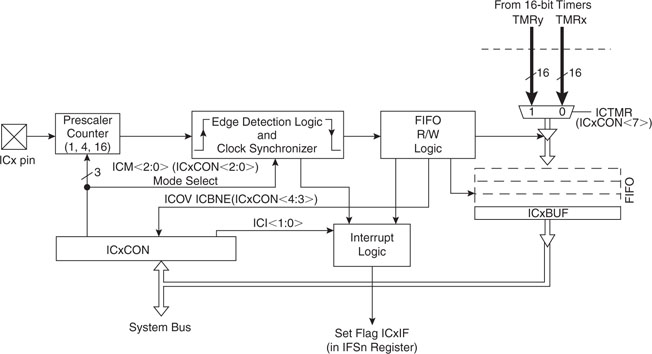
Five input capture modules are available on the PIC32MX360F512L, connected to the IC1-IC5 pins multiplexed on PORTD pins 8, 9, 10, 11, and 12, respectively.
Each input capture module is controlled by a single corresponding control register ICxCON and works in combination with one of two timers, either Timer2 or Timer3.
One of several possible events can trigger the input capture:
The current value of the selected timer is recorded and stored in a FIFO buffer to be retrieved by reading the corresponding ICxBUF register. In addition to the capture event, an interrupt can be generated after a programmable number of events (each time, every second, every third or every fourth).
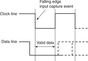
To put the input capture peripheral to use and receive the data stream from a PS/2 keyboard, we can connect the IC1 input (RD8) to the clock line and configure the peripheral to generate an interrupt on each and every falling edge of the clock (see Figure 12.10).
After creating a new project that we will call IC and following our usual template, we can start adding the following initialization code to a new source file we’ll call PS2IC.c:
![]()

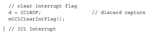
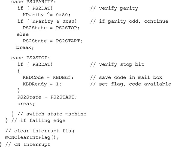
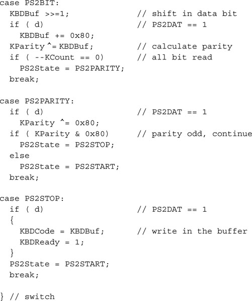
We will also need to create an interrupt service routine for the IC1 interrupt vector. This routine will have to operate as a state machine and perform in a sequence the following steps:
If any of the above checks fails, the state machine must reset and return to the start condition. When a valid byte of data is received, we will store it in a buffer—think of it as a mailbox—and a flag will be raised so that the main program or any other “consumer” routine will know a valid key code has been received and is ready to be retrieved. To fetch the code, it will suffice to copy it from the mailbox first and then clear the flag (see Figure 12.11).
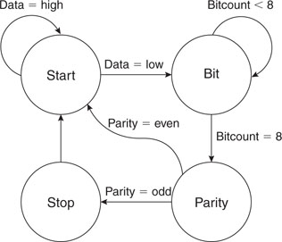
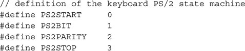
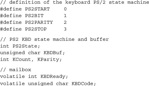
The state machine requires only four states and a counter. All the transitions can be summarized in Table 12.2.
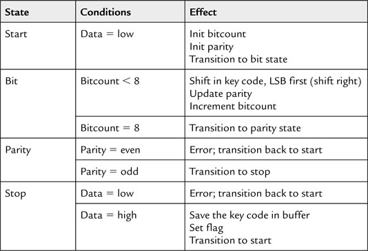
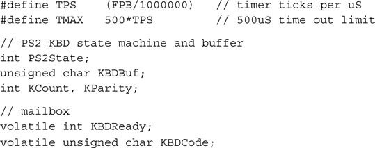
Theoretically I suppose we should consider this an 11-state machine, counting each time the bit state is entered with a different bitcount value as a distinct state. But the four-state model works best for an efficient C language implementation. Let’s define a few constants and variables that we will use to maintain the state machine:
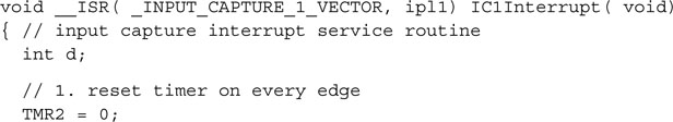
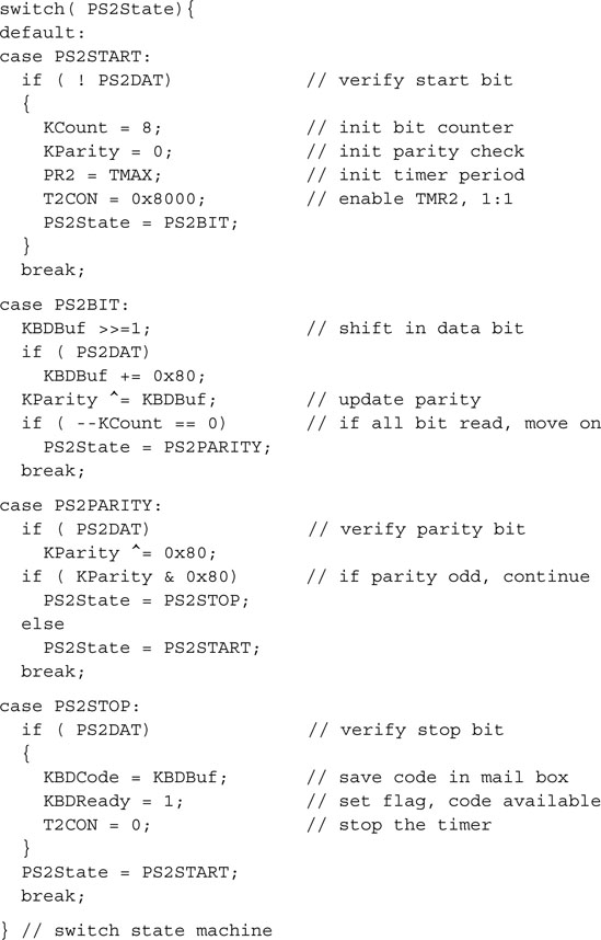
The interrupt service routine for the input capture IC1 module can finally be implemented using a simple switch statement:
Testing Using a Stimulus Scripts
The small perforated prototyping area can be used to attach a PS/2 mini-DIN connector to the Explorer 16 demonstration board, the only alternative being the development of a custom daughter board (PICTail) for the expansion connectors. Before committing to designing such a board, though, we would like to make sure that the chosen pin-out and code is going to work. The MPLAB SIM software simulator will once more be our tool of choice.
In previous chapters we have used the software simulator in conjunction with the Watch window, the StopWatch, and the Logic Analyzer to verify that our programs were generating the proper timings and outputs, but this time we will need to simulate inputs as well. To this end, MPLAB SIM offers a considerable number of options and resources— so many in fact that the system might seem a bit intimidating. First, the simulator offers two types of input stimuli:
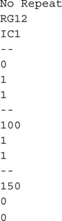
The scripts containing the descriptions of the synchronous stimuli (which can be quite complex) are prepared using the Stimulus window (see Figure 12.12). You must have the MPLAB SIM selected as your active debugging tool (Debugger | Select Tool | MPLAB SIM) to open the Stimulus window by selecting Stimulus | New Workbook from the Debugger menu. To prepare the simplest type of stimulus script, one that assigns values to specific input pins (but also entire registers) at given points in time, you can select the first tab, Pin/Register Actions.
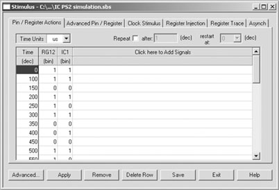
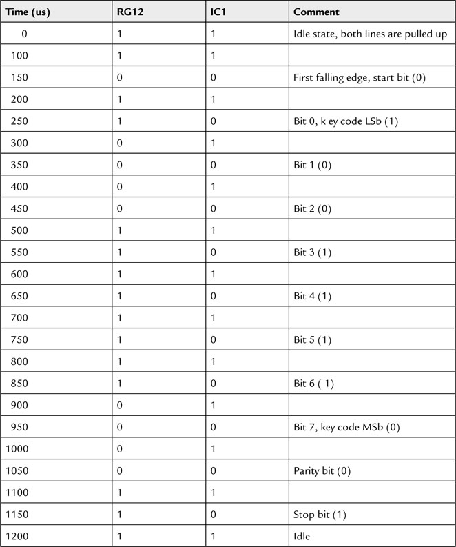
After selecting the unit of measurement of choice, microseconds in our case, click the first row of the table that occupies most of the dialog box window space (where it says “click here to Add Signals”). This will allow you to add columns to the table. Add one column for every pin for which you want to simulate inputs. In our example, that would be RG12 for the PS/2 Data line and IC1 for the Input Capture pin that we want connected to the PS2 Clock line. At this point we can start typing in the stimulus timing table. To simulate a generic PS/2 keyboard transmission, we need to produce a 10 kHz clock signal for 11 cycles, as represented in the PS/2 keyboard waveform in Figure 12.6. This requires an event to be inserted in the timing table each 50us. As an example, Table 12.3 illustrates the trigger events I recommend you add to the Stimulus window timing table to simulate the transmission of key code 0x79.
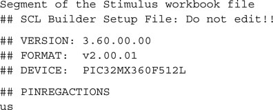
Once the timing table is filled, you can save the current content for future use with the Save button. The file generated will be an ASCII file with the .SBS extension. In theory you could edit this file manually with an MPLAB IDE editor or any basic ASCII editor, but you are strongly discouraged from doing so. The format is more rigid than meets the eye and you might end up trashing it. If you were wondering why the term “workbook” is used for what looks like a simple table, you are invited to explore the other panes (accessible by clicking the tabs at the top of the dialog box) of the Stimulus window. You will see that what we are using in this example is just one of the many methods available, representing a minuscule portion of the capabilities of the MPLAB SIM simulator. A workbook file can contain a number of different types of stimuli produced by any (or multiple) of those panes.
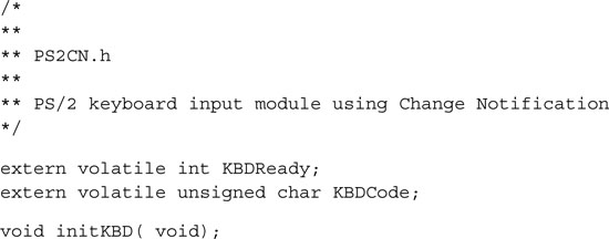
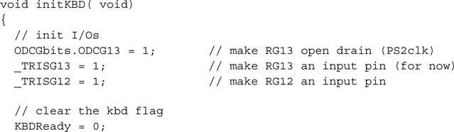
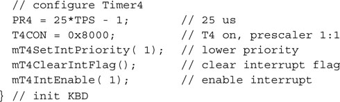
Before we get to use the generated stimulus file, we have to complete the project with a few final touches. Let’s prepare an include file to publish the accessible function: initKBD(), the flag KBDReady, and the buffer for the received key code KBDCode:
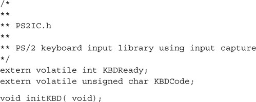
Note that there is no reason to publish any other detail of the inner workings of the PS/2 receiver implementation. This will give us freedom to try a few different methods later without changing the interface. Save this file as PS2IC.h and include it in the project.
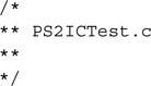
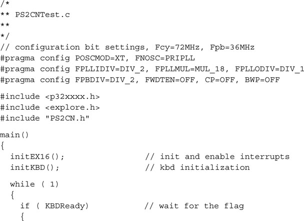
Let’s also create a new file, PS2ICTest.c, that will contain the usual template with the main() routine and will use the PS2IC.c module to test its functionality:
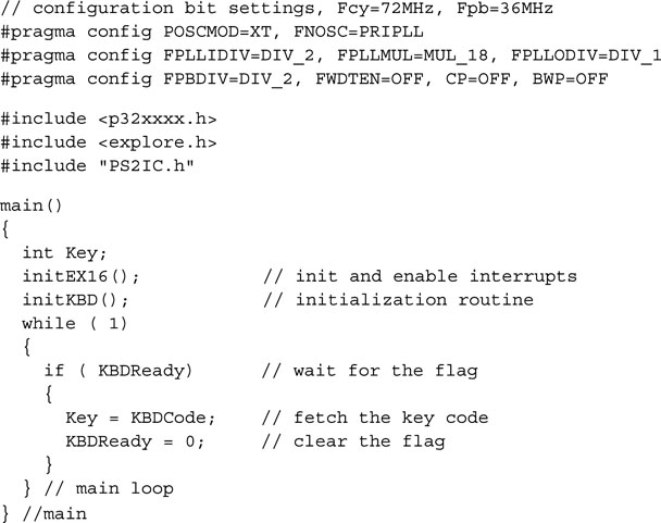
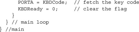
The initEX16() function takes care of the fine tuning of the PIC32 for performance but also enables the vectored interrupts mode. The call to the initKBD() function takes care of the PS/2 state machine initialization, sets the chosen input pins, and configures the interrupts for the Input Capture module. The main loop will wait for the interrupt routine to raise the KBDready flag, indicating that a key code is available; it will fetch the key code and copy it in the local variable Key. Finally, it will clear the KBDReady flag, ready to receive a new character.
Now remember to add the file to the project and build all. Instead of immediately launching the simulation, select the Stimulus window once more, and click the Apply button.
Note
Keep the Stimulus window open (in the background). Resist the temptation to click the Exit button, as that would close the workbook and leave us without stimuli.
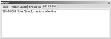
Click the Reset button (or select Debugger | Reset) and watch for the first stimulus to arrive as the microsecond 0 trigger is fired. Remember, both lines RG12 and IC1 are supposed to be set high according to our timetable. A message will confirm this in the Output window (see Figure 12.13).
It is your choice now to proceed by single-stepping or animating through the program to verify its correct execution. My suggestion is that you place a breakpoint inside the main loop on the instruction copying KBDCode to the Key variable. Open the Watch window and add Key from the Symbol list, then RUN.
After a few seconds, the execution should terminate at the breakpoint, and the content of Key should reflect the data we sent through the simulated PS/2 stimulus script: 0x79!
The Simulator Profiler
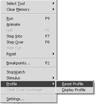
If you were curious about how fast the simulation of a PIC32 could run on your computer, there is an interesting feature available to you in the MPLAB SIM Debugger menu: the profile. Select the Profile submenu (Debugger | Profile) and click Reset Profile (see Figure 12.14).
This will clear the simulator profile counters and timers. Then click the Reset button and repeat the simulation (Debugger | Run) until it encounters the breakpoint again. This time select Debugger | Profiler | Display Profile to display the latest statistics from MPLAB SIM (see Figure 12.15).
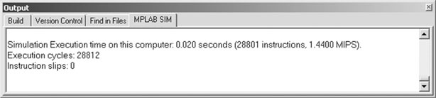
A relatively long report will be available in the output window (MPLAB SIM pane) detailing how many times each instruction was used by the processor during the simulation and, at the very bottom, offering an assessment of the absolute “simulation” speed. In my case, that turned out to be 1.4 MIPS. A respectable result after all, although nothing to write home about. Contrary to the simulation of other PIC® microcontrollers, where these numbers would have compared well with the actual processor real-time performance, compared to the PIC32 the software simulation (on my laptop) ran at just 1/50th of the actual silicon speed!
Change Notification
Though the input capture technique worked all right, there are other options that we might be curious to explore to interface efficiently with a PS/2 keyboard. In particular there is another interesting peripheral available on the PIC32 that could offer an alternative method to implement a PS/2 interface: the Change Notification (CN) module. There are as many as 22 I/O pins connected with this module, and this can give us some freedom in choosing the ideal input pins for the PS/2 interface while making sure they don’t conflict with other functions required in our project or already in use on the Explorer 16 board.
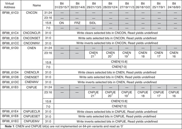
Only three control registers are associated with the CN module. The CNCON register contains the basic control bits to enable the module, and the CNEN register contains the enable bits for each of the CN input pins. Note that only one interrupt vector is available for the entire CN module; therefore it will be the responsibility of the interrupt service routine to determine which one has actually changed if more than one is enabled. Finally, the CNPUE register controls the individual activation of internal pull-up resistors available for each input pin (see Figure 12.16 ).
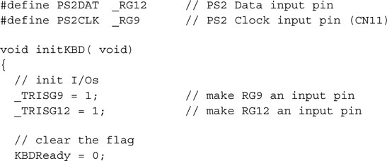
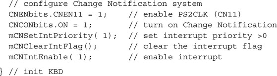
In practice, all we need to support the PS/2 interface is just one of the CN inputs connected to the PS2 clock line. The PIC32 weak pull-up will not be necessary in this case since it is already provided by the keyboard. There are 22 pins to choose from, and we will find a CN input that is not shared with the ADC (remember, we need a 5 V tolerant input) and is not overlapping with some other peripheral used on the Explorer 16 board. This takes a little studying between the device datasheet and the Explorer 16 user guide. But once the input pin is chosen, say, CN11 (multiplexed with pin RG9, the SS line of the SPI2 module and the PMP module Address line PMA2), a new initialization routine can be written in just a couple of lines (see Figure 12.17):
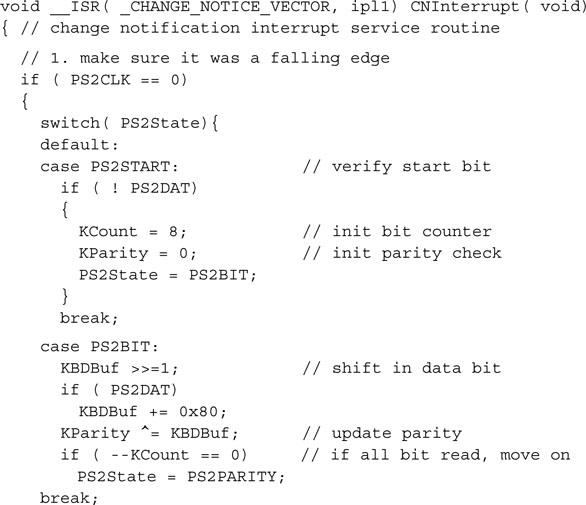
As per the interrupt service routine, we can use exactly the same state machine used in the previous example, adding only a couple of lines of code to make sure that we are looking at a falling edge of the clock line.
In fact, using the input capture module, we could choose to receive an interrupt only on the desired clock edge, whereas the change notification module will generate an interrupt both on falling and rising edges. A simple check of the status of the clock line immediately after entering the interrupt service routine will help us tell the two edges apart:
Add the constants and variables declarations already used in the previous example:
Package it all together in a file that we will call PS2CN.c.
The include file PS2CN.h will be practically identical to the previous example, since we are going to offer the same interface:
Create a new project called PS2CN and add both the .c and the .h files to the project.
Finally, create a main module to test this new technique. One more time, it will be mostly identical to the previous project:
Save the project, then build the project (Project | BuildAll) to compile and link all the modules. To test the change notification technique, we will use once more MPLAB SIM stimulus generation capabilities. Once more we will repeat most of the steps performed in the previous project. Starting with the Stimulus window (Debugger | Stimulus | New Workbook), we will create a new workbook. Inside the window, create two columns, one for the same PS2 Data line connected to RG12, but the PS2 Clock line will be connected to the CN11 Change Notification module input this time. Add the same sequence of stimuli as presented in Table 12.3, replacing the IC1 input column with the CN11 column. Save the workbook as PS2CN.sbs and then click the Apply button to activate the stimulus script.
We are ready now to execute the code and test the proper functioning of the new PS/2 interface. Open the Watch window and add Key from the symbols list. Then set a breakpoint inside the main loop on the line where KBDCode is copied to the Key variable. Finally, perform a reset (Debugger | Reset) and verify that the first event is triggered (setting both PS/2 input lines high at time 0 us). Run the code (Debugger | RUN) and, if all goes well, you will see the processor stop at the breakpoint after less than a second, and you will see the contents of Key to be updated to reflect the key code 0x79. Success again!
Evaluating Cost
Changing from the Input Capture to the Change Notification method was almost too easy. The two peripherals are extremely potent and, although designed for different purposes, when applied to the task at hand they performed almost identically. In the embedded world, though, you should constantly ask yourself if you could solve the problem with fewer resources even when, as in this case, there seems to be abundance.
Let’s evaluate the real cost of each solution by counting the resources used and their relative scarcity. In using the Input Capture, we have in fact used one of five IC modules available in the PIC32MX360F512L model. This peripheral is designed to operate in conjunction with a timer (Timer2 or Timer3), although we are not using the timing information in our application but only the interrupt mechanism associated with the input edge trigger. When using the Change Notification, we are using only one of 22 possible inputs, but we are also taking control of the sole interrupt vector available to this peripheral. In other words, should we need any other input pin to be controlled by the change notification peripheral, we will have to share the interrupt vector, adding latency and complexity to the solution. I would call this a tie.
I/O Polling
There is one more method that we could explore to interface to a PS/2 keyboard. It is the most basic one and it implies the use of a timer, set for a periodic interrupt, and any 5V tolerant I/O pin of the microcontroller. In a way, this method is the most flexible from a configuration and layout point of view. It is also the most generic since any microcontroller model, even the smallest and most inexpensive, will offer at least one timer module suitable for our purpose. The theory of operation is pretty simple. At regular intervals an interrupt will be generated, set by the value of the period register associated with the chosen timer (see Figure 12.18).
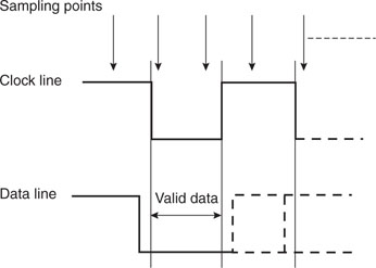
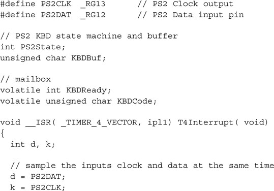
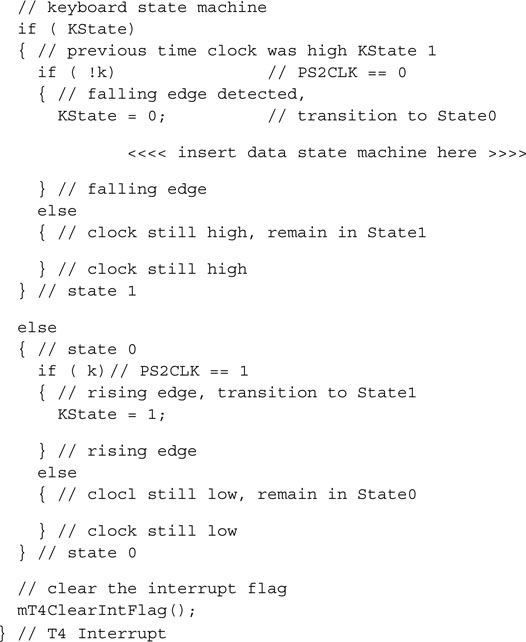
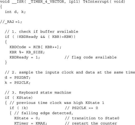
We will use Timer4 this time, just because we never used it before, and its associated period register PR4. The interrupt service routine T4Interrupt() will sample the status of the PS/2 Clock line and it will determine whether a falling edge has occurred on the PS/2 Clock line over the previous period. When a falling edge is detected, the PS/2 Data line status will be considered to receive the key code. To determine how frequently we should perform the sampling and therefore identify the optimal value of the PR4 register, we should look at the shortest amount of time allowed between two edges on the PS/2 clock line. This is determined by the maximum bit rate specified for the PS/2 interface that, according to the documentation in our possession, corresponds to about 16 k bit/s. At that rate, the clock signal can be represented by a square wave with an approximately 50-percent duty cycle and a period of approximately 62.5 us. In other words, the clock line will stay low for little more than 30 us each time a data bit is presented on the PS/2 Data line, and it will stay high for approximately the same amount of time, during which the next bit will be shifted out.
By setting PR4 to a value that will make the interrupt period shorter than 30 us (say 25 us), we can guarantee that the clock line will always be sampled at least once between two consecutive edges. The keyboard transmission bit rate, though, could be as slow as 10 k bit/s, giving a maximum distance between edges of about 50 us. In that case we would be sampling the clock and data lines twice and possibly up to three times between each clock edge. In other words, we will have to build a new state machine to detect the actual occurrence of a falling edge and to properly keep track of the PS/2 clock signal (see Figure 12.19).

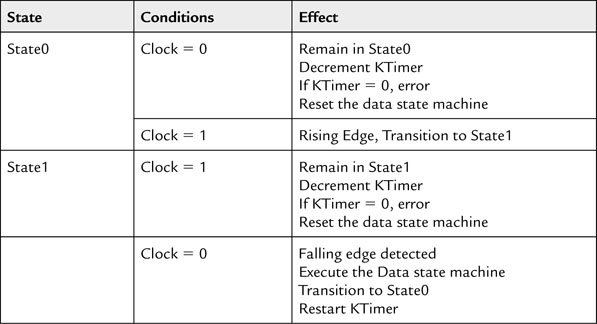
The state machine requires only two states, and all the transitions can be summarized in the Table 12.4.
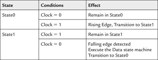
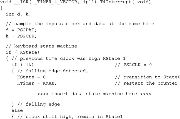
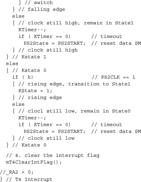
When a falling edge is detected, we can still use the same state machine developed in the previous projects to read the data line. It is important to note that in this case the value of the data line is not guaranteed to be sampled right after the actual falling edge of the clock line has occurred but instead could be considerably delayed. To avoid the possibility of reading the data line outside the valid period, it is imperative to simultaneously sample both the clock and the data line. This will be performed by copying the value of the two inputs in two local variables (d and k) at the very beginning of the interrupt service routine. In our example, we will choose to use RG12 (again) for the data line and RG13 for the clock line. Here is the skeleton implementation of the Clock-polling state machine illustrated previously:
Thanks to the periodic nature of the polling mechanism we just developed, we can add a new feature to the PS2 interface to make it more robust with minimal effort. First, we can add a counter to idle loops of both states of the clock state machine. This way we will be able to create a timeout to be able to detect and correct error conditions, should the PS/2 keyboard be disconnected during a transmission or if the receive routine should lose synchronization for any reason.
The new transition table (Table 12.5) is quickly updated to include the timeout counter KTimer.
The new transition table adds only a few instructions to our interrupt service routine:

Testing the I/O Polling Method
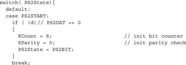
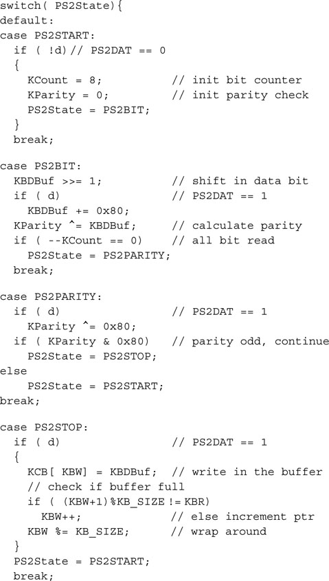
Let’s now insert the Data state machine from the previous projects, modified to operate on the value sampled in d and k at the interrupt service routine entry. It fits entirely in a single switch statement:
Let’s complete this third module with a proper initialization routine:
This is quite straightforward.
Let’s save it all in a module we can call PS2T4.c. Let’s create a new include file, too:
It is practically identical to all previous modules include files, and the main test module will not be much different either:
Create a new project T4 and add all three files to it. Build all and follow the same series of steps used in the previous two examples to generate a stimulus script. Remember that this time the stimulus for the Clock line must be provided on the RG13 pin. Open the Watch window and add PORTA and KBDCode. Finally set a breakpoint to the line after the assignment to PORTA and execute Debug | Run. If all goes well, even this time you should be able to see PORTA updated in the Watch window and showing a new value of 0x79. Success again!
Cost and Efficiency Considerations
Comparing the cost of this solution to the previous two, we realize that the I/O polling approach is the one that gives us the most freedom in choosing the input pins and uses only one resource, a timer, and one interrupt vector. The periodic interrupt can also be seamlessly shared with other tasks to form a common time base if they all can be reduced to multiples of the polling period. The time-out feature is an extra bonus; to implement it in the previous techniques, we would have had to use a separate timer and another interrupt service routine in addition to the Input Capture or Change Notification modules and interrupts.
Looking at the efficiency, the Input Capture and the Change Notification methods appear to have an advantage because an interrupt is generated only when an edge is detected. Actually, as we have seen, the Input Capture is the best method from this point of view, since we can select precisely the one type of edge we are interested in—that is, the falling edge of the PS/2 Clock line.
The I/O polling method appears to require the longest interrupt routine, but the number of lines does not reflect the actual weight of the interrupt service routine. In fact, when we look closer, of the two nested state machines that compose the I/O polling interrupt service routine, only a few instructions are executed at every call, resulting in a very short execution time and minimal overhead.
To verify the actual software overhead imposed by the interrupt service routines, we can perform one simple test on each one of the three implementations of the PS/2 interface. I will use only the last one as an example. We can allocate one of the I/O pins (one of the LED outputs on PORTA not used by the JTAG port would be a logical choice) to help us visualize when the microcontroller is inside an interrupt service routine. We can set the pin on entry and reset it right before exit:
Using MPLAB SIM simulator Logic Analyzer view, we can visualize it on our computer screen. Follow the Logic Analyzer checklist so you will remember to enable the Trace buffer, and set the correct simulation speed. Select the RA0 channel and rebuild the project.
To test the first two methods (IC and CN), you will need to open the Stimulus window and apply the scripts to simulate the inputs. Without them there will be no interrupts at all. When testing the I/O polling routine, you won’t necessarily need it; the Timer4 interrupt keeps coming anyway and, after all, we are interested in seeing how much time is wasted by the continuous polling when no keyboard input is provided.
Let MPLAB SIM run for a few seconds, then stop the simulation and switch back to the Logic Analyzer window. You will have to zoom in quite a bit to get an accurate picture (see Figure 12.20).

Activate the cursors ![]() and drag them to measure the number of cycles between two consecutive rising edges of RA2, marking two successive entries in the interrupt service routine. Since we selected a 25 us period, you should read 900 cycles between calls (25 us * 36 cycles/us @72 MHz).
and drag them to measure the number of cycles between two consecutive rising edges of RA2, marking two successive entries in the interrupt service routine. Since we selected a 25 us period, you should read 900 cycles between calls (25 us * 36 cycles/us @72 MHz).
Measuring the number of cycles between a rising edge and a falling edge of RA2 instead will tell us, with good approximation, how much time we are spending inside the interrupt service routine; 36 cycles is what I found. The ratio between the two quantities will give us an indication of the computing power absorbed by the PS/2 interface. In our case that turns out to be just 4 percent.
Keyboard Buffering
Independently from the solution you will choose of the three we have explored so far, there are a few more details we need to take care of before we can claim to have completed the interface to the PS/2 keyboard. First, we need to add a buffering mechanism between the PS/2 interface routines and the “consumer” or the main application. So far, in fact, we have provided a simple mailbox mechanism that can store only the last key code received. If you investigate further how the PS/2 keyboard protocol works, you will discover that when a single key is pressed and released, a minimum of three (and a maximum of five) key codes are sent to the host. If you consider Shift, Ctrl, and Alt key combinations, things get a little more complicated and you realize immediately that the single-byte mailbox is not going to be sufficient. My suggestion is to use at least a 16-byte first-in/first-out (FIFO) buffer. The input to the buffer can be easily integrated with the receiver interrupt service routines so that when a new key code is received it is immediately inserted in the FIFO.
The buffer can be declared as an array of characters, and two pointers will keep track of the head and tail of the buffer in a circular scheme (see Figure 12.21).
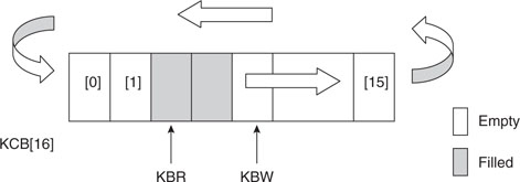
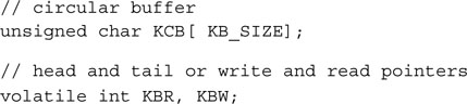
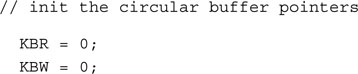
Following a few simple rules, we can keep track of the buffer content:
Insert the following snippet of code into the initialization routine:
Then update the state machine STOP state:
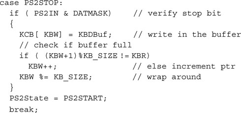
Notice the use of the % operator to obtain the reminder of the division by the buffer size. This allows us to keep the pointers wrapping around the circular buffer.
A few considerations are required for fetching key codes from the FIFO buffer. In particular, if we choose the input capture or the change notification methods, we will need to make a new function available ( getKeyCode() ) to replace the mailbox/flag mechanism. The function will return FALSE if there are no key codes available in the buffer and TRUE if there is at least one key code in the buffer, and the code is returned via a pointer:
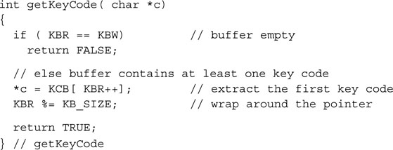
Notice that the extraction routine modifies only the read pointer; therefore it is safe to perform this operation when the interrupts are enabled. Should an interrupt occur during the extraction, there are two possible scenarios:
In both cases there are no particular concerns of conflicts or dangerous consequences.
But if we choose the polling technique, the timer interrupt is constantly active and we can use it to perform one more task for us. The idea is to maintain the simple mailbox and flag mechanism for delivering key codes as the interface to the receive routine and have the interrupt constantly checking the mailbox, ready to replenish it with the content from the FIFO. This way we can confine the entire FIFO management to the interrupt service routine, making the buffering completely transparent and maintaining the simplicity of the mailbox delivery interface. The new and complete interrupt service routine for the polling I/O mechanism is presented here:
Key Code Decoding
So far we have been talking exclusively about key codes, and you might have assumed that they match the ASCII codes for each key—say, if you press the A key on the keyboard you would expect the corresponding ASCII code (0x41) to be sent. But things are not that simple. To maintain a level of layout neutrality, all PC keyboards use scan codes, where each key is assigned a numerical value that is related to the original implementation of the keyboard scanning firmware of the first IBM PC, circa 1980. The translation from scan codes to actual ASCII characters happens at a higher level according to specific (international) keyboard layouts and, nowadays, is performed by Windows drivers. Keep in mind also that for historical reasons there are at least three different and partially compatible “scan code sets.” Fortunately, by default, all keyboards support the scan code set #2, which is the one we will focus on in the following discussion.
Each time a key is pressed (any key, including a Shift or Ctrl key), the scan code associated with it is sent to the host; this is called the make code. As soon as the same key is released, a new (sequence of ) codes is sent to the host; this is called the break code. The break code is typically composed of the same make code but prefixed with 0xF0. Some keys have a 2-byte-long make code (typically the Ctrl, Alt, and arrow keys) and consequently the break code is 3 bytes long (see Table 12.6).
Table 12.6 Example of make and break codes used in Scan Code Set 2 (default).
| Key | Make Code | Break Code |
| A | 1C | F0, 1C |
| 5 | 2E | F0, 2E |
| F10 | 09 | F0, 09 |
| Right Arrow | E0, 74 | E0, F0, 74 |
| Right Ctrl | E0, 14 | E0, F0, 14 |
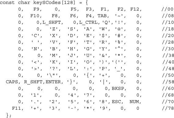
To process this information and translate the scan codes intro proper ASCII, we will need a table that will help us map the basic scan codes for a given keyboard layout. The following code will illustrate the translation table for a common U.S. English keyboard layout:
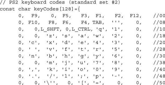
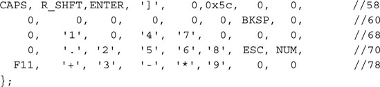
Notice that the array has been declared as const so that it will be allocated in program memory space to save precious RAM space.
It will also be convenient to have available a similar table for the Shift function of each key:
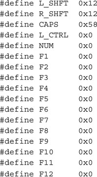
For all the ASCII characters, the translation is straightforward, but we will have to assign special values to the function, Shift, and Ctrl keys. Only a few of them will find a corresponding code in the ASCII set:
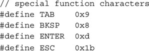
For all the others we will have to create our own conventions or, until we have a use for them, we might just ignore them and assign them a common code (0):
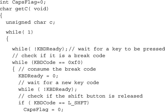
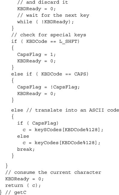
The getC() function will perform the basic translations for the most common keys and it will keep track of the Shift keys status as well as the Caps key toggling:
Debriefing
Today we explored several popular mechanisms used in embedded control to obtain user input. Starting from basic buttons and mechanical switch debouncing, we explored rotary encoders and analyzed the challenges of interfacing to (PS/2) computer keyboards. This gave us the perfect opportunity to exercise two new peripheral modules: Input Capture and Change Notification. We discussed methods to implement a FIFO circular buffer, and we polished our interrupt management skills a little. We managed to learn something new about the MPLAB SIM simulator as well, using for the first time asynchronous input stimuli to test our code. Throughout the entire day our focus has been constantly on balancing the use of resources and the performance offered by each solution.
Notes for the PIC24 Experts
The IC module of the PIC32 is mostly identical to the PIC24 peripheral, yet some important enhancements have been included in its design. Here are the major differences that will affect your code while porting an application to the PIC32:
The CN module of the PIC32 is mostly identical to the PIC24 peripheral, yet some important enhancements have been included in its design. Here are the major differences that will affect your code while porting an application to the PIC32:
Tips & Tricks
Each PS/2 keyboard has an internal FIFO buffer 16 key codes deep. This allows the keyboard to accumulate the user input, even when the host is not ready to receive. The host, as we mentioned at the beginning of this chapter, has the option to stall the communication by pulling low the Clock line at any given point in time (for at least 100us) and can hold it low for the desired period of time. When the Clock line is released, the keyboard resumes transmissions. It will retransmit the last key code, if it had been interrupted, and will offload its FIFO buffer.
To exercise our right to stall the keyboard transmissions as a host, we have to control the Clock line with an output using an open drain driver. Fortunately, this is easy with the PIC32, thanks to its configurable I/O port modules. In fact, each I/O port has an associated control register (ODCx) that can individually configure each pin output driver to operate in open-drain mode.
Note that this feature is extremely useful in general to interface PIC32 outputs to any 5V device. In our example, turning the PS/2 Clock line into an open-drain output would require only a few lines of code:
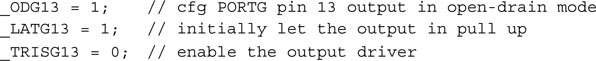
Note that, as usual for all PIC microcontrollers, even if a pin is configured as an output, its current status can still be read as an input. So there is no reason to switch continuously between input and output when we alternate sending commands and receiving characters from the keyboard.
Exercises
Books
Nisley, Ed. The Embedded PCs ISA Bus (Annabooks/Rtc Books, 1997). Speaking of legacy interfaces, the ISA bus, the heart of every IBM PC for almost two decades, is today interestingly surviving in some industrial control “circles” (like the PC104 platform) and embedded applications.
Links
www.computer-engineering.org. This is an excellent Web site where you will find a lot of useful documentation on the PS/2 keyboard and mouse interface.
www.pc104.com/whatis.html. The PC104 platform, one of the first attempts at bringing the IBM PC architecture to single-board computers for embedded control.