
Day 14 Mass Storage
The Plan
In many embedded-control applications, you might find a need for a larger nonvolatile data storage space well beyond the capabilities of the common Serial EEPROM devices and the Flash program memory available inside the microcontroller itself. You might be looking for orders of magnitude more—hundreds of megabytes and possibly gigabytes. If you own a digital camera, an MP3 player, or even just a cell phone, you have probably become familiar with the storage requirements of consumer multimedia applications and with the available mass storage technologies. Hard disk drives have become smaller and less power thirsty, but also a multitude of solid state solutions (based once more on Flash technologies such as Compact Flash, Smart Media, Secure Digital, Memory Stick, and others) have flooded the market, and because of the volumes absorbed by the consumer applications, the price range has been reduced to a point where it is possible, if not convenient, to integrate these devices into embedded-control applications.
In this lesson we will learn how to interface one of the most common and inexpensive mass storage device types to a PIC32 microcontroller using the smallest amount of processor resources.
Preparation
In addition to the usual software tools, including the MPLAB® IDE, the MPLAB C32 compiler, and the MPLAB SIM simulator, this lesson will require the use of the Explorer 16 demonstration board, an In-Circuit Debugger of your choice), and a soldering iron and a few components you’ll need ready at hand to extend the board capabilities using the prototyping area or a small expansion board. You can check on the book’s companion Web site (www.exploringPIC32.com) for the availability of expansion boards that will help you with the experiments.
The Exploration
Each one of the many competing mass storage technologies has its strengths and weaknesses, since each was designed for a somewhat different target application. We will choose the ideal mass storage media for our applications according to the following criteria:
The Secure Digital (SD) card standard compares favorably in all those aspects; today it is one of the most commonly adopted mass storage media for digital cameras and many other multimedia consumer applications. The SD card specifications represent an evolution of a previous technology known as Multi Media Card, or MMC, with which they are still partially (backward) compatible both electrically and mechanically. The Secure Digital Card Association (SDCA) owns and controls the technical specification standards for SD memory cards, and they require all companies that plan to actively engage in the design, development, manufacture, or sale of products that utilize the SD specifications to become members of the association. As of this writing, a general SDCA membership will cost you $2,000 in annual fees. The Multi Media Card Association (MMCA), on the other side, does not require implementers to become members and makes copies of the MMC specifications available for sale starting at $500. So both technologies are far from free or “open” by any means.
Fortunately there is a “subset” of the SD specifications that has been released to the public by the SDCA in the form of a “simplified physical specification”. This information is truly all we need to develop a basic understanding of the SD/MMC memory technology and get started designing a PIC32 mass storage interface.
The Physical Interface
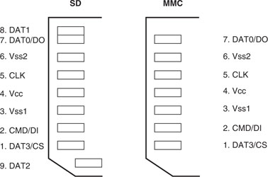
SD cards require only nine electrical contacts and an SD/MMC compatible connector, which can be purchased through most online catalogs for less than a couple of dollars. The connector requires only a couple of pins more to account for insertion detection and write protection switch sensing. Two main modes of communication are available: the first one (known as the SD bus) is original to the SD/MMC standard and it requires a nibble (4-bit) wide bus interface; the second mode is serial and is based on the popular SPI bus standard. It is this second mode that makes the SD/MMC mass storage devices particularly appealing for all embedded-control applications, since most microcontrollers will either have a hardware SPI interface available or will be able to easily emulate one (bit-banging) with a reduced number of I/Os. Finally, the physical specifications of the SD/MMC cards indicate an operating voltage range of 2.0 V to 3.6 V that is ideally suited for all application with modern microcontrollers implemented in advanced CMOS geometries, as is the case of the PIC32MX family (see Figure 14.1).
Note
Logically and electrically, miniSD cards, microSD cards, and SD cards are identical. Only the form factor, size, and number of pins are different from the original standard. Both the miniSD cards and microSD cards were designed to meet special size requirements. With an adapter or an appropriate connector, they can be used in the following application.
Interfacing to the Explorer 16 Board
Unfortunately, although the number of electrical connections required for the SPI interface is very small, all SD/MMC card connectors available on the market are designed for surface-mount applications only, which makes it almost impossible to breadboard a card interface or use the prototyping area of the Explorer 16 demonstration board.
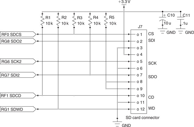
Since in the previous chapters we used the first SPI peripheral module (SPI1) to produce a video output and the application does not allow for sharing the resource, we will share instead the second SPI module (SPI2) between the SD card interface and the EEPROM interface using separate Chip Select (cs) signals for the two. In addition to the usual SCK, SDI, and SDO pins, we will provide pull-ups for the unused pins (reserved for the 4-bit-wide SD bus interface) of the SD/MMC connector and for two more pins that will be dedicated to the Card Detect and Write Protect signals (see Figure 14.2).
Note
Microchip has recently made available an expansion board known as the PICTail® Daughter Board for SD and MMC Cards (AC164122) that can be effectively used to complete all the projects presented in this chapter. An alternative set of pin assignments to support the new PICTail board will be offered on the companion web site: www.ExploringPIC32.com.
Starting a New Project
After creating a new project that we will obviously call SDMMC, let’s start writing the basic initialization routines for all the necessary I/Os and the configuration of the SPI2 module:
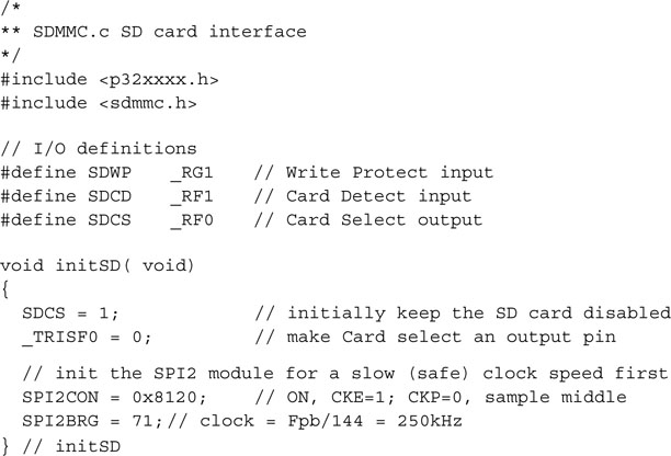
In particular, in the SPI2CON register we need to configure the SPI module to operate in master mode with the proper clock polarity, clock edge, input sampling point, and an initial clock frequency. The clock output (SCK) must be enabled and set low when idle.
The sampling point for the SDI input must be centered. The frequency is controlled by means of the SPI baud rate generator (SPI2BRG) that divides the peripheral clock (Tpb). After power-up and until the SD card is properly initialized, we will have to keep the SPI clock speed to a safe setting, below 400 kHz; therefore we will use a setting of Tpb/144 to obtain a 250 kHz clock signal. This is just a temporary arrangement, though; after sending only the first few commands, we will be able to speed up the communication considerably.
Notice how only the SDCS signal (RF0 pin) needs to be manually configured as an output pin, whereas SCK2 and SDO2 (corresponding to the RG6 and RG8 pins) are automatically configured as outputs as soon as we enable the SPI 2 peripheral.
Selecting the SPI Mode of Operation
When an SD/MMC card is inserted in the connector and powered up, it starts in the default mode of communication: the SD bus mode. To inform the card that we intend to communicate using the alternative SPI mode, all we need to do is to select the card (SDCS pin low) and start sending the first reset command. We can be assured that once it’s entered the SPI mode, the card will not be able to change back to the SD bus mode unless the power supply is cycled. However, this means that if the card is removed from the slot without our knowledge and then reinserted, we will have to make sure that the initialization routine or at least the reset command are repeated, to get back to the SPI mode. We can detect the card presence at any time by checking the status of the SDCD line (RF1 input pin).
Sending Commands in SPI Mode
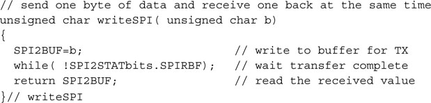
In SPI mode, commands are sent to an SD/MMC card as packets of 6 bytes, and all responses from the SD card are provided with multiple byte data blocks of variable length. So all we need to communicate with the memory card is the usual basic SPI routine to send and receive (the two operations are really the same, as we have seen in the previous chapters) a byte at a time:
For improved code readability and convenience, we will also define two more macros that will mask the same writeSPI () function as a pure readSPI (), or just as a clock output function clockSPI (). Both macros will send a dummy byte of data (0xFF)
![]()
To send a command, we will start selecting the card (SDCS low) and send through the SPI port a packet composed of three parts:
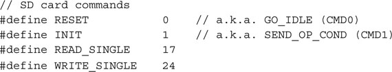
The Cyclic Redundancy Check (CRC) feature is always used in SD bus mode to make sure that every command and every block of data transmitted on the bus is free from error. But, as soon as we switch to the SPI mode after sending the reset command, the CRC protection is automatically disabled and the CRC value is ignored. In fact, from that moment on, the card assumes that a direct and reliable connection to the host, the PIC32 in our case, is available. By taking advantage of this default behavior, we can simplify our code by using a single precomputed value. This will be the CRC code of the RESET command. For all the subsequent commands, the CRC field will be a “don’t care.” Here is the first part of the sendSDCmd() function that we will use to send all commands to the SD card:
After sending all 6 bytes to the card, we are supposed to wait for a response byte. In fact, it is important that we keep sending “dummy” data continuously clocking the SPI port. The response will be 0xFF; basically, the SDI line will be kept high until the card is ready to provide a proper response code. The specifications indicate that up to 64 clock pulses, or 8 bytes, might be necessary before a proper response is received. Should we exceed this limit, we would have to assume a major malfunctioning of the card and abort communication:
If we receive a response code, each bit, if set, will provide us with an indication of a possible problem (see Table 14.1 ).
Table 14.1 SD card Command Response codes.
| Bit | Description |
| 0 | Idle state |
| 1 | Erase Reset |
| 2 | Illegal command |
| 3 | Communication CRC error |
| 4 | Erase sequence error |
| 5 | Address error |
| 6 | Parameter error |
| 7 | 0 (always) |
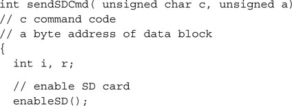
Notice that, on return, the sendSDCmd() function leaves the SD card still selected (SDCS low) so that commands such as Block Write and Block Read, which require additional data to be sent to or received from the card, will be able to proceed. In all other commands that do not require additional data transfers, we will have to remember to deselect the card (set SDCS high) immediately after the function call. Furthermore, since we want to share the SPI2 port with other peripherals such as the Serial EEPROM mounted on the Explorer 16 board, we need to make sure that the SD/MMC card receives a few more clock cycles (eight will suffice) immediately after the rising edge of the chip select line (SDCS). According to the SD/MMC specifications, this will allow the card to complete a few important housekeeping chores, including the proper release of the SDO line, essential to allow other devices on the same bus to communicate properly.
Here is another pair of macros that will help us perform this consistently:
![]()
Completing the SD Card Initialization
Before the card can be effectively used for mass storage applications, a well-defined sequence of commands needs to be completed. This sequence is defined in the original MMC card specifications and has been modified only slightly by the SD card specifications. Since we are not planning on using any of the advanced features specific to the SD card standard, we will use the basic sequence as defined for MMC cards for maximum compatibility. There are five steps in a sequence that starts as soon as the card is inserted in the connector and powered up:
The following segment of the function initMedia() will perform exactly those initial five steps:
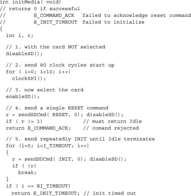
The initialization command can require quite some time, depending on the size and type of memory card, normally measured in several tenths of a second. Since we are operating at 250 kb/s, each byte sent will require 32 us. If we consider 6 bytes for every command retry, using a count up to 10,000 will provide us with a generous timeout limit (I_TIMEOUT) of approximately three tenths of a second as per SD card specifications.
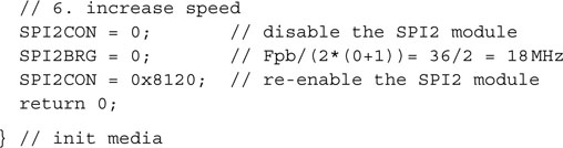
It is only upon successful completion of the preceding sequence that we will be allowed to finally switch gear and dramatically increase the clock speed to the highest possible value supported by our hardware. With minimal experimentation you will find that an Explorer 16 board, with a properly designed daughter board providing the SD/MMC connector, can easily sustain a clock rate as high as 18 MHz. This value can be obtained by reconfiguring the SPI baud rate generator for a 1:2 ratio. We can now complete the initMedia() function with the last segment:
Reading Data from an SD/MMC Card
SD/MMC cards are solid-state devices typically containing large arrays of Flash memory, so we would expect to be able read and write any amount of data (within the card capacity limits) at any desired address. In reality, compatibility considerations with many previous (legacy) mass storage technologies have imposed a number of constraints on how we can access the memory. In fact, all operations are defined in blocks of a fixed size that by default is 512 bytes. It is not a coincidence that 512 bytes is the exact standard size of a data “sector” of a typical personal computer hard disk. Although this can be changed with an appropriate command, we will maintain the default setting so that later we will be able to take advantage of this compatibility. In the next chapter we will develop a set of routines that will allow us to implement a complete file system compatible with the most common PC operating systems. This way we will be able to access files written on the SD card by a personal computer, and vice versa, a personal computer will be able to access files written by our applications onto an SD card.
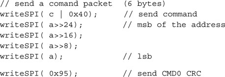
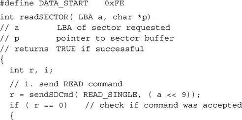
The READ_SINGLE (CMD17) is all we need to initiate a transfer of a single sector from a given address in memory. The command takes as an argument a 32-bit “byte address,” but when accessing sectors of data, we will be constantly referring to logical block addresses, or LBAs, borrowing from a term used in other mass storage applications.
![]()
To avoid confusion, in the following we will uniformly use only LBAs or block addresses, and we will obtain an actual byte address by multiplying the LBA value by 512 just before passing the parameter to the READ_SINGLE command.
Writing a sector of data to an SD card requires the following five steps:
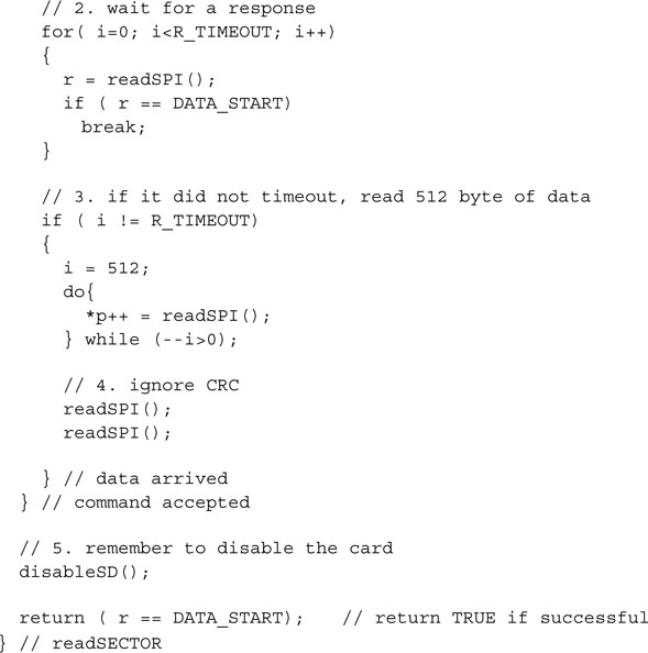
The following routine readSECTOR() performs the entire sequence in a few lines of code:
Note
To provide a visual indication of activity on the memory card similarly to hard drives and diskette drives, we could assign one of the LEDs available on the Explorer 16 board as the “read” LED, hoping this will help prevent a user from removing the card while in use. The LED can be turned on before each read command and turned off at the end.
Other strategies are possible, though. For example, similarly to common practice on USB Flash drives, an LED could be turned on as soon as the card is initialized, regardless of whether an actual command is performed on it at any given point in time. Only calling a deinitialization routine would turn the LED off and indicate to the user that the card can be removed.
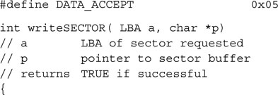
Writing Data to an SD/MMC Card
Based on the same considerations we made for the readSECTOR() function, we will develop a writeSECTOR() function that will be similarly constrained to operate on 512-byte-wide blocks of data. The write sequence we will use, as you would expect, is the WRITE_SINGLE command and will be composed of five steps. However, this time the data transfer will be in the opposite direction:
It is only at this point that we will deselect the memory card and terminate the entire write command sequence:
Note
Similarly to the readSECTOR() function, a second LED can be assigned to indicate when a write operation is being performed and alert the user. Should the card be removed during the write sequence, data will most likely be lost or corrupted.
Save the source we developed so far in a file called SDMMC.c to be placed inside the lib directory. We will have ample use for it in the next few chapters.
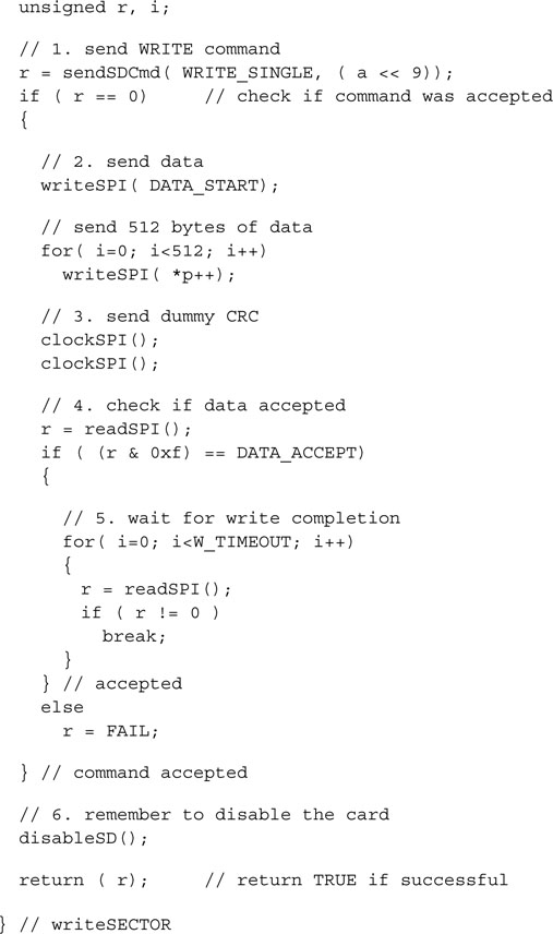
As a final nice touch, we should add the following two functions to manage the SD/MMC connector switches:
When a card is inserted in the connector, the Card Detect switch is closed and the SDCD input pin is pulled low. The getCD() function will allow us to detect the card’s presence by returning TRUE when the card is inserted and ready for use.
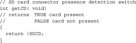
Similarly, when the Write Protection tab on the card is not in the “lock” position and the card is inserted, the Write Protect switch will close and the corresponding SDWP input pin will be pulled low.
The getWP() function, called when the card is properly inserted, will return TRUE if the card is locked.
Notice that the Write Protect tab on the SD/MMC card is similar to cassette and VHS tape protection tabs. It is merely suggesting that the device should not be written to.
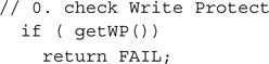
So it is our responsibility to respect the user’s desire and implement a check for the WP switch at the beginning of our writeSECTOR() function and abort immediately if the lock is set.
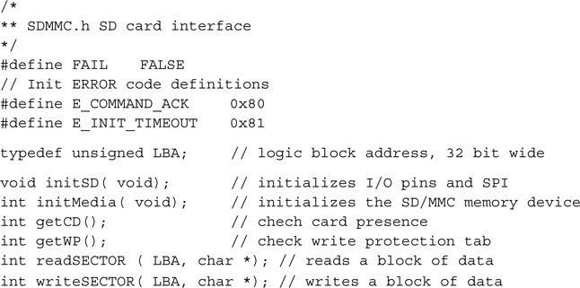
Finally, let’s create a new include file called SDMMC.h that we will save in a common include directory to provide the prototypes and basic definitions used in the SD/MMC interface module:
Testing the SD/MMC Interface
Whether you believe it or not, the four minuscule routines we just developed are all we need to gain access to the seemingly unlimited amount of “storage space” offered by the SD/MMC memory cards. For example, a 1GB SD card would provide us with approximately 2,000,000 (yes, that is 2 million) individually addressable memory blocks (sectors), each 512 bytes large. Note that as of this writing, SD/MMC cards of this capacity are normally offered for retail in the United States for less than $20!
Let’s develop a small test program to demonstrate the use of the SD/MMC module. The idea is to simulate a somewhat typical application that is required to save some large amount of data on the SD/MMC memory card. A fixed number of blocks of data will be written in a predetermined range of addresses and then read back to verify the successful completion of the process. We will use the LCD to report diagnostic information and track the progress.
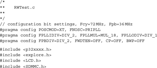
Let’s create a new source file that we will call RWTest.c, and let’s start by adding the usual header and processor specific include files, followed by the new sdmmc.h library:
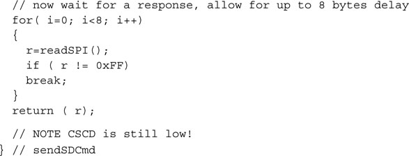
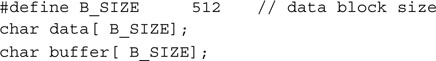
Then let’s define two byte arrays, each the size of a default SD/MMC memory block that is 512 bytes:
The test program will fill the first array with a specific and easy to recognize pattern and will repeatedly write its contents onto the memory card. The chosen address range will be defined by two constants:
![]()
The LED2 connected on the PORTA RA2 pin on the Explorer 16 demonstration board will provide us with visual feedback about the SD card usage status. Notice that this I/O is available even if you are using the PIC32 Starter Kit and therefore the JTAG port is enabled:
![]()
The first few lines of the main program can now be written to initialize the I/Os required
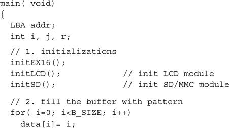
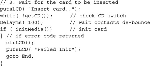
The next code segment will prompt the user to insert the card in the slot and will check for the presence of the SD card in a loop. After a short debouncing delay, the initialization routine is performed to prepare the card to receive SPI commands:
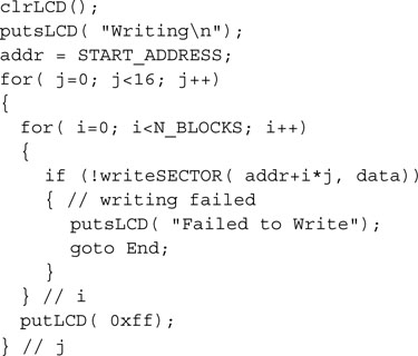
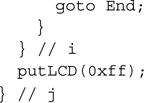
When ready, we proceed with the actual data writing phase. The LED is turned on to indicate that the SD card is in use, and a status message is printed on the first line of the LCD display. Two nested loops repeatedly call the writeSECTOR() function to write 16 groups of 10 sectors starting at the absolute LBA=10,000. Every 10 sectors (approx. 5 KBytes) a brick character (black box) is added on the second line of the LCD display to form a progress bar. Should any write command fail, the procedure is immediately aborted and an error message is reported on the LCD:
![]()
Then it is time to read back each sector of data and verify its content. After the LCD is updated to reflect the new phase, the same two nested loops perform the reading and verification in groups of 10 sectors. After each group of sectors is read and verified, a new brick (black bar) is added to the display to indicate the progress. Should any of these steps fail, the procedure is immediately aborted and an error message is displayed on the LCD:

Notice how the memcmp() function, part of the standard C string.h library, is used to efficiently perform the data comparison. It returns a zero value when the two buffers’ content is identical, a nonzero value otherwise.
If all went well, a success message is printed on the LCD and the LED is turned off, since the SD card is no more in use and can now be removed:
Make sure to add all the required source files—SDMMC.h, SDMMC.c, LCDlib.c, explore.c, and RWTest.c—to the project, then build all and program the Explorer 16 board with your in-circuit debugger of choice. You will need a daughter board with the SD/MMC connections as described at the beginning of the lesson and an empty SD card to perform the test.
Warning
This is the real thing! When you run the RWTest program, the contents of the SD card will be modified, overwriting any data on the card and potentially corrupting any files. Make sure you have saved all the family photos and your favorite MP3 files somewhere else! Only in the next chapter we will develop a library compatible with common PC “file systems.” It will allow us to share the SD card without risk of damaging existing files, reading and writing data using a common format.
As you run the code, the efforts of building the SD/MMC interface (or the expense of purchasing one) will be more than compensated by the joy of seeing the PIC32 perform the test flawlessly in a few seconds.
Also, admire how small the overall amount of code and resources we used was (see Figure 14.3)!
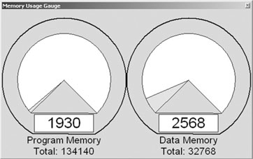
All together, the test program and the SD/MMC access library module have used only 1.930 words of the processor Flash program memory—that is, less than 2 percent of the total available memory. Not to mention that, as in all previous lessons, this result was obtained with all compiler optimization options turned off.
Debriefing
In my personal opinion, it does not get cheaper or easier than this with any other mass storage technology. After all, we can use only a handful of pull-up resistors, a cheap connector, and just a few I/O pins to enormously expand the storage capabilities of our applications. In terms of PIC32 resources required, only the SPI peripheral module has been used, and even that could be shared with other applications.
The simplicity of the approach has his obvious limitations, though. Data can be written only in blocks of fixed size, and its position inside the memory array will be completely application specific. In other words, there will be no way to share data with a personal computer or other device capable of accessing SD/MMC memory cards unless a “custom” application is developed. Worse, if an attempt is made to use a card already used by a PC, PC data would likely be corrupted and the entire card might require complete reformatting. In the next lesson, we will address these issues by developing a complete file system library.
Tips & Tricks
The choice of operating on the default block size of 512 bytes was dictated mostly by historical reasons. By making the low-level access routines in this lesson conform with the standard size adopted by most other mass storage media devices (including hard drives), we made developing the next layer (the file system) easier. But if we were looking for maximum performance, this could have been the wrong choice. In fact, if we were looking for faster write performance, typically the bottleneck of every Flash memory media, we would be better off looking at much larger data blocks.
Flash memory typically offers very fast access to data (reading) but is relatively slow when it comes to writing. Writing requires two steps: First, a large block of data (often referred to as a page) must be erased; then the actual writing can be performed on smaller blocks. The larger the memory array, the larger, proportionally, the erase page size will be. For example, on a 512 Mbyte memory card, the erase page can easily exceed 2k bytes. Although these details are typically hidden from the user as the main controller inside the card takes care of the erase/write sequencing and buffering, they can have an impact on the overall performance of the application. In fact, if we assume a specific SD card has a 2k byte page, writing any amount of data (<2k) would require the internal card controller to perform the following steps:
By performing write operations only on blocks of 512 bytes each, to write 2 k bytes of data our library would have to ask the SD card controller to perform the entire sequence four times, whereas it could be done in just one sequence by changing the data block length or using a multiple-block write command. Although this approach could theoretically increase the writing speed by 400 percent in our example, consider the option carefully because the price to pay could be quite high. In fact, consider the following drawbacks:
Exercises
Books
Schmidt, F., The SCSI Bus and IDE Interface: Protocols, Applications, and Programming, second edition ( Addison-Wesley Professional, New york, 1999 ). If the SD card interface has intrigued you for its simplicity, you might now be curious about the interfaces used on most of the older (nonsolid-state) mass storage devices used in the world of personal computers. You will see they were not that much more complex.
Axelson, J., USB Mass Storage: Designing and Programming Devices and Embedded Hosts (Lakeview Research, WI, 2006). This book continues the excellent series on USB by Jan Axelson. Low-level interfacing directly to an SD/MMC card was easy, as you have seen in this chapter, but creating a proper USB interface to a mass storage device is a project of a much higher order of complexity.
Links
www.mmca.org/home. The official Web site of the MultiMedia Card Association (MMCA).
www.sdcard.org. The official Web site of the Secure Digital Card Association (SDCA).
www.sdcard.org/Sdio/Simplified%20SDIO%20Card%20Specification.pdf. The simplified SDIO card specifications. With SDIO, the SD interface is no longer used only for mass storage but is also a viable interface for a number of advanced peripherals and gizmos, such as GPS receivers, digital cameras, and more.