Chapter 17. Scribe Integration Components
In this chapter, we examine common integration scenarios and how the Scribe Workbench and Scribe Console toolsets can be used for each of them.
The scenarios we review are migration (or data replication), integration (or data synchronization), and process integration. While the scenarios and the examples provided cover a majority of situations, we have found that every integration is unique in some way, and the solutions presented should provide enough illustration for integration challenges particular to your organization.
As mentioned, the three most common integration scenarios are as follows:
• Migration, or data replication: A common and straightforward integration use case is the need to replicate data from one application to other applications in one direction. For example, a company may want to replicate contract expiration data from its contracts management system into its CRM application. By having up-to-date contract data, users can conduct effective marketing and sales campaigns targeted at renewing customers and designed to increase renewal rates and recurring revenue. Identifying those records that change in the contracts system and updating the CRM application with those changes is the most efficient way to ensure that the CRM users have the most current information.
• Integration, or data synchronization: In this scenario, a company has two or more applications that contain the same information, and it wants to ensure that all copies of that information are consistent. For example, a company may have information on customers (contact names, addresses, phone numbers, and so on) in both a CRM and enterprise resource planning (ERP) application. If a customer notifies the billing department of an address change and that change is made in the ERP application, it is important that the new address be reflected in the CRM application, too. This consistency of data drives more efficiency and avoids embarrassing missteps with customers. Given that changes may occur to data in any of the applications, updates will be moving in multiple directions. This type of bidirectional integration process places significant pressure on the timeliness and reliability of the net change capture mechanism.
• Process integration: In many cases, the actions of a user within a business application can trigger a business process that spans multiple applications. The most common example of a process type integration is the quote to order process that spans across a company’s CRM and ERP application. A typical process initiation is the submission of the sales order by a salesperson within the CRM application. This new order transaction needs to be captured and delivered to the ERP application for processing by the back-office operation. As with data synchronization, these types of integrations are bidirectional and underscore the need for a timely and reliable net change approach.
The Scribe product line addresses these three scenarios through two different toolsets: the Scribe Workbench and the Scribe Console.
Table 17.1 outlines the various features of each tool and how they map to the previously outlined integration scenarios.
Table 17.1 Integration Options
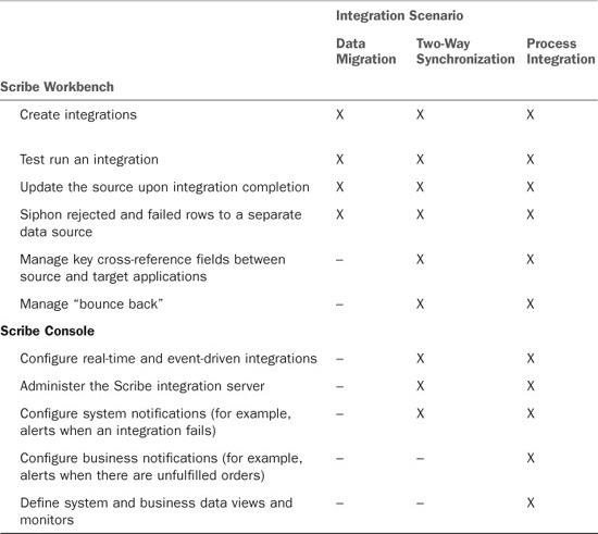
In this chapter, we also review the consequences associated with changed data and the impact across the integration design.
Note
This concept of changed data across an integrated environment is referred to as the net change pattern.
Data Migration (Replication)
Data migration, or data replication, is, as you might expect, the least complex scenario. That doesn’t mean that it is any less significant, or easier to perform correctly than the other scenarios. In fact, it is common to perform a migration multiple times as part of the overall validation process.
In this section, we review how to perform a migration using the Scribe toolset.
Scribe Workbench
The Scribe Workbench (shown in Figure 17.1) is the main Scribe tool for managing migrations. The Scribe Workbench enables users to define both source and target data sets. Either or both of these may be a specific application (such as Microsoft Dynamics CRM, Microsoft Dynamics NAV, Salesforce, or other applications) or may be a more generic data set (such as SQL Server, XML, ODBC, and others).
Figure 17.1 The Scribe Workbench.
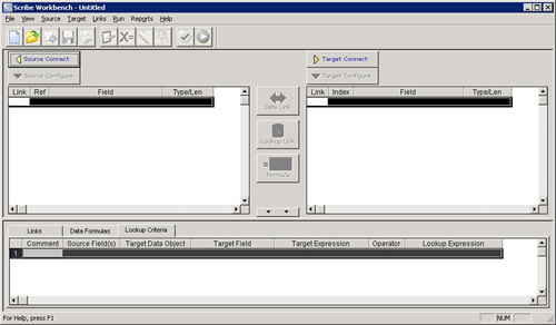
After defining both a source and a target, users can relate the two systems together using a linking/mapping window. Linked fields can incorporate formulas (custom formulas and 180+ functions that ship with the product) to calculate or transform data in the mapping window, too.
Choosing the source and target, linking fields, and creating formulas all combine to create what is referred to as an integration definition. Users can choose to run the integration manually through mouse clicks in the Scribe Workbench.
Other options are also configured in the Scribe Workbench and are considered part of this integration definition, including the following:
• Source and target definitions
Source and Target Definitions
As part of the definition of an integration, users define both source and target data. When possible, using one of the Scribe application adapters is the best option because each adapter is built to work with its respective application and is optimized based on that application’s API. However, connecting to data via generic connection types (such as ODBC, XML, and others) is also supported.
Adapters also act as a layer of indirection between your integrations and the application. Scribe adapters keep a consistent development interface that will insulate the integration creator from changes in the applicable system. The differences between Microsoft Dynamics CRM 3.0 and 4.0 provide a good example of this. Although the technical differences between these two releases are significant, the Scribe adapter for Microsoft Dynamics CRM looks and acts essentially the same for both versions. For Scribe integrations, upgrading to Microsoft Dynamics CRM 4.0 is as easy as upgrading the Scribe adapter.
Source Configuration
Defining the source data begins with choosing how to connect to the data (using an application adapter, ODBC, or XML). After you choose the connection parameters, a series of prompts helps you define the query set for the source data. This can be a single “object” or can be a custom query joining multiple objects together.
When you join multiple objects, the syntax is much like SQL. You can define calculated values in the Scribe Workbench (referred to as variables) that filter on a static or dynamic values.
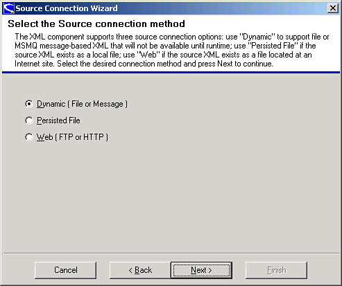
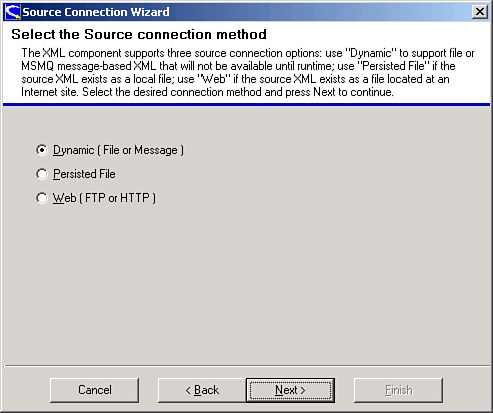
Figure 17.2 shows the Source Connection Wizard that prompts for the source connection method.
Figure 17.2 The Scribe Source Connection Wizard.
Target Configuration
Choosing the target system is nearly identical to choosing the source data, but the process varies after you have provided the necessary connection parameters.
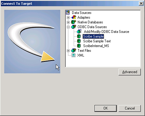
Figure 17.3 shows the Scribe target connection options.
Figure 17.3 The Scribe target connection options.
A “target” in the Scribe Workbench consists of both the locations in the target system and how the target data is structured (including transaction integrity).
Suppose, for example, that you are integrating sales orders into a target system. Often, the sales header will be a different location than the sales lines. Therefore, you define the target system as both places. Furthermore, you most likely attempt to integrate the lines after the header has been successfully integrated.
In this example, integrating into the sales header and sales lines would be represented as steps. A step has an action (for example, an insert or update) and a workflow of what you want to happen as each step passes, and what you want to happen should the step fail. You can chain these steps together based on the result of a given step. The Scribe Workbench contains a graphical representation of this flow, showing the workflow of behaviors based on various results of the steps defined. When you preview or test an integration, you will see the steps, or route, each record being integrated follows, as shown in Figure 17.4.
Figure 17.4 Configuring a target example.
Mapping and Linking Options
Scribe Insight makes some intelligent decisions about data transformation and management based on how you relate the source and target data sets to each other. For example, Scribe retains the cross-referential integrity between two systems based on key fields defined in the two systems. To accomplish this, there are two ways to link fields in the Scribe Workbench:
• Links
• Formulas
Links
A data link is the traditional mapping relationship between two fields in two separate systems. By choosing to relate to fields using a data link, you are stating that you want to change the value in the target to the value in the source.
A lookup link defines the relationship between the source and target fields a bit differently. A lookup link tells Scribe that the two fields (or, more specifically, the relationship between the two fields) define how the two data sets relate to each other. You can customize how these two fields relate to each other; for example, the first four characters of the source key field should align to the last four characters of the target key field.
Formulas
You can choose to use any of the 180+ formulas included with the product to transform data as it moves from source to target. Alternatively, you can create your own formulas in Visual Basic 6.0.
Many of the core formulas are data driven, so you can modify or extend their behavior by adding content to the appropriate Scribe database table (specifically the SCRIBE.FunctionList table). Applications for this feature include modifying the data used by fuzzy logic functions available within Scribe and adding permutations for lookup.
Additional Functions
Although not in direct support of the migration of data, the Scribe Workbench allows some other functionality worth mentioning.
Test Window
The Test window lets you to step through each record being integrated. This preview includes the original source content, the target value (including any transformation or formula applied to the link), and the step control.
To open the Test window, on the Run menu, click Test.
Update Source
Upon successfully integrating a given record, a value can be written back to a field in the source. This feature is commonly used to mark a row as having been successfully integrated. This value can be a string literal or a calculated value (using a formula).
The feature is available in the Source Configuration window.
Rejected Rows
When a record fails to integrate, you can opt to have a copy of the source data saved in a separate data source. This can prove useful when there are larger sets of data and you want to review failed records without sifting through the entire source data set. Furthermore, by redirecting rejected source rows to a different location, you can focus solely on those rows.
For example, if 150 rows fail out of 20,000, the rejected source rows table will contain only the 150 failed rows. Working with a set of 150 rows is much easier than working with a row of 20,000 (especially when you are trying to troubleshoot an issue).
On the Run menu, click Edit Settings. Then use the Rejected Source Rows tab.
Key Cross Reference
One of the common issues when trying to integrate data between disparate systems is that values that uniquely identify an entity in one application do not match up nicely with values used to identify that same entity in the other system. For example, Microsoft Dynamics GP uniquely identifies a customer using an alphanumeric quasi-“human-readable” string; whereas Microsoft CRM uses a globally unique identifier (GUID). Scribe offers the Key Cross Reference feature as a way to coordinate these unique/”key” values across disparate systems.
Over time, these unique identifiers (databases refer to them as a “key”; hence the feature name) are collected in a Scribe table. The more identifiers tracked, the more efficient your integrations become. The efficiency comes in Scribe’s capability to resolve an alphanumeric value to a GUID without having to make calls in to CRM, for example.
These unique values can be leveraged in formulas, too. For example, if you want to use the key value of the Microsoft Dynamics GP customer as a note on the account in Microsoft CRM, you can reference the unique GP customer ID as a formula on the account’s Note field.
To manage key cross references, on the Links menu, click Cross-Reference Keys.
Data-Migration Example
Life will be easier for you if you create a CRM Adapter publisher as the first step, because the CRM Adapter publisher is responsible for capturing changes that occur in CRM, and uses that change event to trigger an integration to occur (for example, integrate a new account into the ERP system.)
The publisher will publish data in a specific schema, however. Creating the publisher first will allow you to get that schema for use when creating the actual integration.
Note
Depending on your version of Microsoft Dynamics CRM, you may need to customize CRM to publish changes before creating a Scribe CRM adapter publisher.
• CRM 3.0 uses the “call-out” functionality.
• CRM Live uses workflow to publish changes.
• Microsoft Dynamics CRM 4.0 makes use of “plug-in” technology.
The Scribe CRM adapter Help outlines how to configure these various versions of Microsoft Dynamics CRM.
This section assumes you have already made any necessary customizations to Microsoft Dynamics CRM based on the version.
Creating a CRM Adapter Publisher
1. Open the Console and go to the Publisher and Bridges node under Integration Server.
2. Create a new publisher, and make its type Microsoft Dynamics CRM Publisher. You will be prompted for connection information when you move to the next step of the creation process.
3. After the connection to CRM has been established, you need to indicate what CRM entities you want to monitor for change; where a change in an entity of that type (add/delete/update) triggers some event in your integration solution (for example, starts an integration). To indicate which entities you want to use as indicators of change, go to step 4 of the publisher-creation process and click the Add button.
4. Select Account as your Dynamics CRM entity that will be used to start an integration. Select the Insert operation to indicate that when new accounts are created you want Scribe to publish information about the related account. Select the Update operation to indicate that when existing accounts are changed you want Scribe to publish information about the related account.
Figure 17.5 shows the publisher entry that is created at this step.
Figure 17.5 Scribe publisher entry.
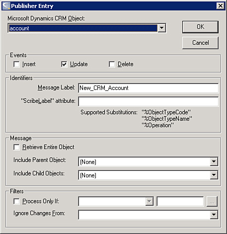
Although not required, we have created a message label for continuity with other examples in this chapter.
Note
Be sure to remember this label because you will need it when creating the integration process that gets started when a new CRM account is created (or updated)
5. While still on step 4 of the publisher-creation process, click the XML Schema’s button and save the XDR someplace you can get to later. This is the schema that you can use to create integrations against (for example, create an integration definition for what should happen when a new account is created).
Now that you’ve created the CRM adapter publisher, we’ll create a data migration.
Creating a Data Migration
1. Open the Workbench and select XML as a source.
2. Use the Dynamic (File or Message) option, as shown in Figure 17.6.
Figure 17.6 Scribe Source Connection Wizard.
You’ll be prompted for both a schema and a sample file.
Note
Although you don’t need the sample file to create the integration definition, you won’t be able to run the integration without real data.
Because we have already created a CRM publisher (our first step), we can get an XML file with real data by just creating an account in Microsoft Dynamics CRM.
If your publisher is showing as active (not paused), after a short time you will have a message in your ScribeIn queue. In the Scribe Console, you can open this Microsoft Message Queuing (MSMQ) message and opt to Save Body. This option will create an XML document that conforms to the schema as defined by the publisher and will contain “real” data based on the CRM entity you created.
Note
If the message does not show up in the ScribeIn queue, make sure your Integration Process is active (e.g., not paused). The message may have been routed to the ScribeDeadMessage queue as well.
3. Link to the schema file that defines what your source data will look like. The “sample” file is optional, but you will not be able to run the integration if there is only a schema (that is, no data).
4. Connect to the target application by using the Scribe Sample ODBC database connection, as shown in Figure 17.7.
Figure 17.7 Connect to Target dialog box.
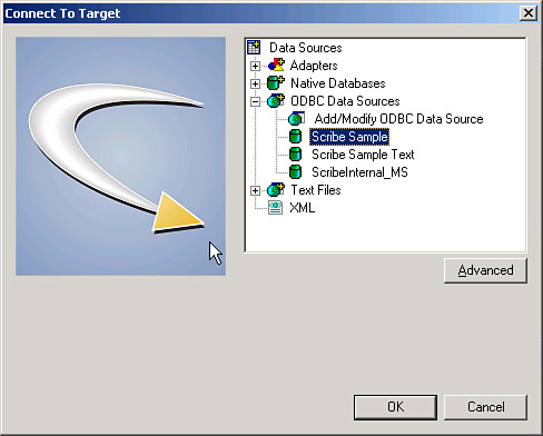
The Scribe Sample uses SCRIBE as the user ID and integr8! as the password.
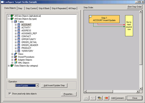
5. After the target has been defined, select the Account table.
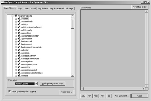
With Operation set to Insert/Update, click Add Insert/Update, as shown in Figure 17.8.
Figure 17.8 Scribe target configuration sample.
Note
By defining the target in this way, you are stating that for each new source record you want to insert a new record in the Account table in the target. If that record already exists, update it instead.
6. After the source and target have been defined, map the following fields from source to target:
Map source field Name to target column ACCOUNTNAME using the Data Link button.
Map source field accountnumber to target column ACCOUNTID using the Data Link button.
Map these same source and target fields (accountnumber and ACCOUNTID) using the Lookup Link button.
Note
A lookup link is used to test if a record exists. (And in this case, ACCOUNTID is a primary key field on the target table Account.) A data link maps the value in the source to the target field.
7. Save and run the integration. After it has completed, your new row should be in your target.
8. While still in the Workbench, select the PHONE target column.
9. Click the Formula button and make the formula read as "(xxx) 123-1234". You will need quotes here because this is a string literal.
10. Save and run the integration again. The row should be updated with this new value in the PHONE column.
Note
If you receive Primary Key violations on this second run, ensure that the lookup links defined previously are accurate with respect to the constraint being violated.
Data Integration (Synchronization)
This section provides more information about the Scribe tools and describes how they work in data-synchronization scenarios. This section introduces the major features of each tool, including how they can be used
Scribe Console
Creating event-driven integrations begins with using the Scribe Workbench to define the integration (for example, what should happen when the integration commences based on some event). The Scribe Console is used to configure integrations to run automatically when one or more conditions are met (as opposed to starting the integration manually from the Scribe Workbench).
Collaborations
Integrations are aligned with a logical collection of jobs called a collaboration in the Scribe Console. You might configure one collaboration to process sales lead events. Then you might configure a second collaboration to process order events.
It makes sense to store these collaboration files in a logical folder structure. For example, create a folder named Sales and a second folder named Orders.
By compartmentalizing integrations and related items, you will be able to manage and report against your integrations more easily.
Each collaboration has these parts:
• Integration processes: A collection of integration definitions, each keyed to run off of a specific event (see later in this chapter for specific examples).
• Monitoring: Monitors work hand in hand with alerts. Monitors are used to measure and report system health indicators (for example, unhandled message in an MSMQ, or unfulfilled sales orders). Monitors and alerts are covered in more detail in the “Process Integration” section.
• File browser: A direct view in to the folder associated with this collaboration.
• Alert log: A history of alerts over time. This log has some useful workflow management capabilities, too (such as being able to mark alerts as being “acknowledged” or as having been “handled”).
• Data views: A data view is a report based on a query written against an adapter. The data views result set can be represented in tabular or graphical form. For a collaboration, you may want to see representations of the number of sales orders integrated over time, for example.
For real-time and two-way integrations, the integration processes node is where you will spend much of your time. One of the first decisions you need to make is choosing the event that will trigger when an integration is run:
• File: Periodically checks for the existence of a particular file in a particular location. If that file is detected, the integration is run. You can choose to rename or even delete the file after the integration has finished.
• Time: Runs the integration based on a time event. Time-based events can be repeating.
• Query: Runs the integration when a particular query returns a result set.
• Queue: Runs the integration when a message is received in a specific MSMQ. A single MSMQ can serve multiple integrations, and you can use the message header or the root node of the incoming XML document to refine which integrations are run. Queue-driven integration processes and related parts are covered later in this chapter.
Integration Server
Although a particular Scribe deployment can have many Scribe Consoles and Workstations on a variety of computers, one computer must be designated as the integration server (see Figure 17.9). It is this computer that coordinates real-time integrations and from which you monitor overall system health. In fact, when using the Scribe Console from a separate computer, you are actually pointing to resources on this central integration server.
Figure 17.9 Integration server.
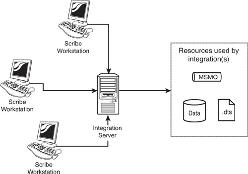
This allows you to manage who has access to the integration resources (for example, the Scribe application) apart from who has access to Scribe. Suppose, for example, you are integrating into an ERP system that contains payroll information. You might not want users who have access to Scribe to have access to the payroll information. (And therefore the Scribe application does have access, but users might not.)
Within the Scribe Console, there is an additional node for the integration server. The options here let you manage and monitor resources used by various integrations:
• Integration processes: Nearly identical to the option of the same name under a specific collaboration. This view rolls up all integration processes across all collaborations rather than a single collaboration.
• Publishers and bridges: Publishers and bridges are used to manage net change between two applications. Publishers and bridges are covered in more detail in the “Process Integration” section.
• Monitoring: Monitors found under the Integration Server node are technically identical to monitors listed under each collaboration node. The monitors listed here, however, are meant to be used for integration server monitoring (whereas the monitors listed with a given collaboration are meant to be used for monitoring business activities related to the specific collaboration).
• Queue browser: Lists the MSMQs currently available to the Scribe server to the Scribe Console. Unlike the MSMQ view in MSC, you can resubmit failed messages by dragging them from the ScribeDeadMessage queue and dropping them into the ScribeIn queue.
• File browser: Exposes file system resources available to the Scribe server to the Scribe Console.
• Services: Exposes windows services available to the Scribe server to the Scribe Console.
Administration
Scribe system administration is also managed through the Scribe Console. Scribe system administration consists of reviewing results of integrations over time, responding to and managing Scribe system alerts, choosing system-level resources that the Scribe system should have access to, and more:
• Execution log: Review a list of integrations over time. The list can be filtered by integration process or result (failure, success).
• Alert log: Similar to alert logs in collaborations, alerts in the administration alert log should reflect an alert pertaining to overall system health (whereas alert logs in collaborations represent an alert that affects that collaboration). As an example, an alert on the administration side may be used to signal that there are more than 1,000 items in the execution log, whereas an alert in a collaboration may signal that there are unfulfilled orders older than a predefined term.
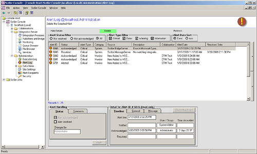
• The alert log can be used to manage alerts, too. You can mark an alert as being acknowledged and then resolved. The Scribe alert log, shown in Figure 17.10, tracks timestamps and comments associated with these changes.
Figure 17.10 Scribe alert log.
• Data views: Much like data views at the collaboration level. As with alert logs, data views on the administration side part of the Scribe Console report on overall system health as opposed to a business-related collaboration activity. For example, a data view at the administration level may be the number of failed integrations over time, whereas a collaboration data view might be the number of new orders over time.
• Site settings: The Scribe system administrator can define some system-level options, including email server location (for alert delivery) and system sleep options (so that integrations are paused during a predefined backup period, for example).
• Alert recipients: Used to define recipient users, recipient groups, or recipient maps of users to be alerted. A recipient user has some sort of address (such as an email address) to which the notification will be sent. A recipient group is a collection of one or more users.
• A recipient map lets you create abstract groups. An example best demonstrates this feature: You create a monitor based on a SQL query. One of the columns contains the values A, B, or C. In the definition of that query monitor, you can bind that column such a recipient map, where the elements of that recipient map are titled A, B, or C. If the value of the query is A, the users and groups associated with element A in the map will be notified.
• Security: The Scribe system administrator needs to explicitly designate a system resource to be listed in the file browser, queue browser, and services nodes described earlier. This node helps facilitate that process.
MSMQ-Driven Integration Processes
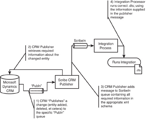
For queue-driven integration processes, you should be aware of some intrinsic predefined message queues. To help with context, let’s assume you are looking to create new customers in the ERP/back-office system whenever a new account is created in Microsoft Dynamics CRM. Therefore, this event begins when a new account is created in Microsoft Dynamics CRM. A piece of Scribe technology called a publisher oversees this change management process.
In this case, the Microsoft Dynamics CRM adapter has a few different publishers (depending on whether you are using Microsoft Dynamics CRM On-Line, Microsoft Dynamics CRM Hosted, or Microsoft Dynamics CRM On Premise). The publisher’s duty, at this point, is to recognize that the change occurred and to signal to Scribe that an entity in Microsoft Dynamics CRM has been modified, inserted, or deleted. To accomplish this, a lightweight message is dropped into a publisher-specific MSMQ. Scribe often refers to this as the PubIn queue. (You can have many publishers monitoring Microsoft Dynamics CRM, with each potentially using its own MSMQ—so the exact MSMQ name is determined at publisher creation time.) The “lightweight” message includes the entity changed, the nature of the change, and enough information to uniquely identify the specific entity or entities that changed.
Messages on the PubIn queue are picked up by a publisher, and the information required to perform the integration is retrieved. By using this two-step process when creating a publisher, you can define the process so that changes to one entity (such as an account in Microsoft Dynamics CRM) actually retrieve information from other entities (all addresses for that account) in addition to the entity that changed. In this way, the first step serves as a generic handler to signal to the publisher that a change has occurred, while the second step is the publisher retrieving all the information necessary based on its definition.
After the complete information is retrieved from the source application (in this case, Microsoft Dynamics CRM), a message is added to ScribeIn MSMQ. Unlike the PubIn queue, the ScribeIn queue is an MSMQ named ScribeIn and is created when you install Scribe. All queue-based integration processes will be listening on this queue. (Note how you do not specify a specific MSMQ when creating an MSMQ-driven integration process.) For what it is worth, if you are opposed to using ScribeIn as the default MSMQ and want to use a different MSMQ, you can define the Scribe input queue in the Administration’s Site Settings node.
After a message is in the ScribeIn queue, Scribe finds and runs the correct integration definition based on the settings used when creating the integration process.
Finally, when creating an integration in the Scribe Workbench, you mark the integration to be automatically retried should it fail. (For example, you are integrating customers and orders in real time across many queues; on the off-chance that an order comes through before the customer, you may want to automatically retry versus having it fail with a “customer does not exist” error.)
To do this, on the Target Configure window’s Step Control tab, choose the Failure option. In the list of results, change the On Failure control from Goto Next Row to End Job. Make sure that the Exit Status is set to Retry.
Figure 17.11 Publish process flow.
Data-Integration Example
To create an event-driven integration in the Console, follow these steps:
Note
We are assuming that you have followed the steps outlined previously in this chapter to create a CRM adapter publisher. (During that process, you will have defined a message label, which will be used when creating an integration process in this example.)
1. Open the Console, and move to the Integration Processes node for a specific collaboration.
2. Click the Add button.
3. Select Queue as the event type, give the integration process a name, and then select a DTS that should be invoked.
Note
If you get an error stating that your collaborations folder is not authorized, make sure you have defined the scribe collaborations folder in the security node (Administration, Security, File Browser).
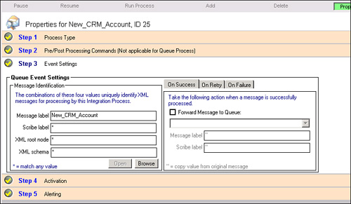
4. At step 3 of the integration process creation, change the message label from a wildcard (*) to match the message label you defined when creating your publisher, as shown in Figure 17.12.
Figure 17.12 Scribe properties, event settings.
Note
Changing the message label will ensure that only messages with the proper label will be routed to this particular integration process, giving you the control to associate messages from a specific publisher to a specific integration process.
5. Moving to another step of the integration process creation will allow you to save the integration process.
6. After you have finished creating the integration process, select the integration process you just created and click the Pause button.
Note
Pausing the integration process will enable you to see (and diagnose) various steps in the integration pipeline. Normally, you keep the integration unpaused.
7. Create a new account in CRM. If you’ve configured your publisher, you will see a new message in the ScribeIn queue.
Note
If you don’t see a message in the ScribeIn queue, ensure that your publisher was created according to the “Creating a CRM Adapter Publisher” section.
8. Select the integration process you just created and click the Resume button. The integration process will remove that new message and process it.
A new account created in CRM should automatically flow straight through to your target application (as defined in the .dts you created).
Note
If the message remains in the ScribeIn queue, make sure the integration process is set to use a queue (versus time, file, or query events). If it is, confirm the message label associated with this integration process matches the message label being placed on the message by the publisher.
Process Integration
Now that you have created an integration in the Workbench and configured any real-time integration requirements in the Console, there are a number of features of Scribe that will help you manage some of the common issues that arise in real-time integration solutions.
Bounce-Back
One of the frequent issues integrators need to resolve is bounce-back. Bounce-back occurs in two-way integrations when changes in one application trigger an integration in a second application and the changes in this second application trigger changes back in the first. Ultimately, the same change bounces back and forth between the two systems.
To avoid this bounce-back, you define the integration solution such that changes should not be published out of the second integration if they are from a specific user. Scribe refers to this user as the integration user. Configuring this is a two-step process:
1. When defining an integration in the Scribe Workbench, open the Settings - Adapter window (found under Source, Adapter Settings or under Target, Adapter Settings), as shown in Figure 17.13. In the Run As tab, choose the user you want to be tagged as having performed this integration.
Figure 17.13 Scribe adapter settings.
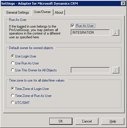
2. When configuring your publisher, choose to ignore messages from a certain user and choose the same user you chose to “run as,” earlier.
Note
Currently, only two adapters support this functionality: the Scribe Adapter for Microsoft Dynamics CRM and the Scribe Adapter for Microsoft Dynamics NAV.
Monitors
There are two different types of monitors that behave similarly:
• System monitors: System monitors are monitors that report on overall Scribe system health. System health indicators may be items such as the number of integrations over a period of time or they could be the number of failed integrations over time.
• Business activity monitors: Business activity monitors use the same technology but are more focused on business goals than on system health. Examples of business activity monitors may include the number of customers added in CRM over time or the average time to fill an order grouped by date.
A Scribe user can create a monitor through the Scribe Console. Monitors can be set up to work off of a “query” or a “queue.” For query monitors, you write SQL-like syntax to form a query. Query monitors “alert” when the result set meets or exceeds a certain row count or based on the value of a field.
Queue monitors listen in on an MSMQ queue. You can define which messages will be monitored by customizing the message label, the XML schema of the message contained in a particular MSMQ message, and other similar message traits. Like query monitors, alerts can be tied to a number of messages in the queue. A common use for queue monitors is to ensure that communications between systems are happening efficiently (for example, by setting a monitor to alert the Scribe administrator if the number of messages in the ScribeIn MSMQ climbs over 100).
Data Views
Data views are meant to present information in tabular or graphical forms. Think of data views as key performance indicator (KPI) reporting meters. Users can create a data view to report on a metric.
Scribe Application Publishers, Query Publishers, and Bridges
A key part of process integration is the capability for the extended system to respond to a user-driven event in one part of the system. For example, the system needs to be able to respond to a user adding an account in Microsoft Dynamics CRM to drive the relevant information into the ERP/back-office system. Scribe supports a variety of ways to accommodate this need:
• Query publishers: A query publisher is a mechanism where the Scribe user would define a query. Results from this query represent items to be managed. An example is returning all the CRM accounts that have not been brought over to ERP. Each row of the result set should be then brought over. Alternatively, you can take a “snapshot” of the results of a query and publish only those items that differ from the snapshot.
• In either case, the resulting rows can be grouped if you routinely expect large result sets and want to optimize the integration event.
• This mechanism is a “poll” type of approach, where Scribe periodically (at a time interval configured by the user) runs the query and reacts to the result set returned.
• Adapter publishers: Query publishers operate on a “poll” basis, where periodically a change is made to see whether new data exists to be published. Some applications, however, signal themselves when a change has occurred.
• In these cases, instead of making periodic checks, the application signals when new content is ready. This approach is useful when you are concerned with the amount of unnecessary network chatter a query publisher may produce, or if “near real-time” integration is not good enough. Real-time is when the event of the changing data initiates the process, near real-time is when a periodic check is made and the events age could be equal to the period of that check. (That is, if your query publisher checks once a minute, changes found may be up to a minute old.)
• To use an adapter publisher, you must complete some additional configuration in the application in question. For Microsoft Dynamics CRM, for example, you might need to configure a workflow. Scribe has preconfigured units (SQL triggers, sample workflows, or custom call-outs depending on the technology at hand) that make this configuration as easy as possible.
• Email bridges: Email bridges are similar to publishers in concept but differ in implementation. Email bridges listen to an email alias at a specific email server for incoming email messages. When an email message is received, the bridge adds a message on the ScribeIn MSMQ queue with the body contents (or an attachment) as the source data.
Net Change Patterns
In all three integration scenarios previously described, capturing changed data from a source application is a fundamental component of the integration design. This section reviews some of the key considerations for net change capture and their impact on the overall integration process. Then we present four “best practice” design patterns for net change, outlining the pros and cons of each pattern, along with some design tips to ensure the effectiveness of each pattern.
The following are some of the important considerations when designing a net change capture mechanism:
• Efficiency: The most efficient net change approaches minimize the number and size of messages based on the needs of the integration process. This minimizes the burden on the network and the applications involved in the integration. When messaging and communications are minimized, integration processes perform better, are less prone to error, and are simpler to troubleshoot.
• Reliability: Robust integration processes require that all record modifications and business events that meet the criteria defined in the process are captured and published. Failure to capture everything results in data integrity issues and broken business processes.
• Bounce-back prevention: Bounce-back or echoing occurs most often when synchronizing data between two applications. Let’s say that a net change mechanism is in place for a CRM application that will send an account change to an ERP application for processing. If ERP receives a change from CRM, and ERP’s net change mechanism has no way to ignore that change, the change initiated in CRM will be bounced back and processed against CRM. If CRM also has no way to ignore changes from ERP, the change would be trapped in an endless loop. Bounce-back prevention depends on the ability to ignore any changes created by the integration process.
• Real-time processing: Many integration processes require that changes be processed within seconds or minutes. This is particularly important when the business users require minimal latency in synchronized data or where time-sensitive business processes are involved.
• Transaction sequencing: Business processes across multiple applications often involve dependency across multiple transactions, where the sequence in which the transactions are processed is critical. Take the example of order processing between a CRM and ERP application. Let’s say a user within the CRM application creates an order for a new customer. To process that order in the ERP application, a customer record must first be created in ERP before the order can be processed. CRM will need to publish both the new customer transaction and the order transaction to ERP. Ensuring the proper sequencing of these transactions avoids unnecessary errors and minimizes “retry” processing.
• On-demand application support: On-demand or Software as a Service (SaaS) applications by design do not allow access to the database layer, thereby limiting options for establishing net change mechanisms. Many on-demand application providers impose limits on the number of information requests each customer may make within a time period, thereby placing a premium on highly efficient processing.
• Delete support: Certain design patterns provide little or no support for capturing the deletion of records.
• Guaranteed message delivery: Just publishing a changed record or business transaction is not enough. Mechanisms need to be built in to the end-to-end integration process to ensure that all records are processed fully.
• Multicast support: Many integration processes involve more than two applications. In these cases, changed records or transactions may need to be published and processed against two or more applications.
The remainder of this chapter discusses four common net changes patterns used in integration processes today. Note that this is not an exhaustive list; these are just the more prevalent approaches. These four patterns are as follows:
• Pattern 1: Application publisher
• Pattern 3: Modified date/timestamp
• Pattern 4: Snapshot comparison
Pattern 1: Application Publisher
This pattern leverages functionality available within the source application to proactively publish changes based on the occurrence of a specific event within the source application. The application publisher approach generally leverages workflow capabilities within the application, and in many ways can behave similarly to database triggers, yet function at the application level.
Figure 17.14 shows a typical application publisher scenario.
Figure 17.14 Typical application publisher scenario.
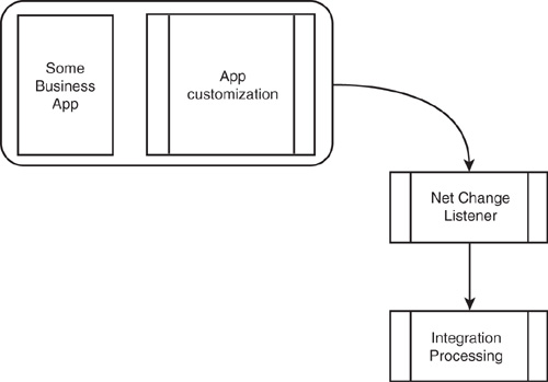
Whereas Microsoft Dynamics CRM supports notifications, most application architectures do not support this capability. Therefore, the cases where this pattern can be applied are limited. However, when available, this pattern combines the best real-time support with the greatest efficiency because an action is initiated only in the event of a specified data change or application event.
Pattern 1 Pros
• Provides real-time, event-driven notification of changes. There is no polling burden or overhead cost to either the application or database server.
• Usually supports deletes.
• Normally a highly reliable method with little chance of overlooking data changes or events.
Pattern 1 Cons
• Requires special application- and adapter-specific publisher support. This capability can be used only if the application architecture provides a change notification or call-out capability. Most application architectures do not support or provide change notification or call-out capability. The trend within the application industry is toward adding publisher mechanisms, particularly in the on-demand market given the pressure to limit the number of calls that each customer can make against his or her application instance within a 24-hour period.
• This pattern may not support filtering by user to prevent bounce-back.
Pattern 1 Implementation Tips
Changes tend to be queued in the order in which they occur, but this is not guaranteed. You might need to design your integration processes to handle out-of-sequence messages, including building in retry mechanisms to account for the potential of out-of-sequence messages.
If you are trying to send header/line-item (or master/detail) changes together, you will need to determine whether required line-item changes will always trigger a header notification. If not, account for notification of line-item changes, too. You might be able to configure both header/line-item and line-item-only changes to return messages with the same structure. The preferred method for capturing header/line-item changes is to wait for a specific user-requested action (like clicking a Submit button). This will prevent the system from sending multiple messages when a header and several line-items are entered or modified.
Pattern 2: Modified Flag
This pattern enables the tracking of changes by toggling off and on a synchronized flag or field; off when a change is made to the data in the source application, and on when the change has been processed against the target application. This approach depends on application (or source system) logic to toggle the synchronized flag off whenever a change is made (see Figure 17.15). The most common way to enable this synchronized flag is by creating database triggers and a shadow table within the source application database to perform this function. Triggers are added to each application base table for which you need to track changes. The triggers add or update a record in the shadow table to track the change.
Figure 17.15 Typical modified flag scenario.
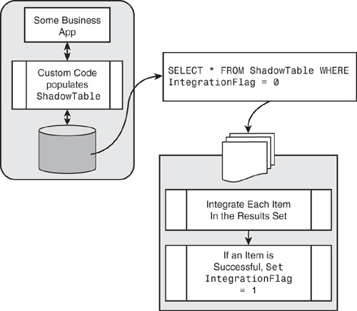
The most efficient way to implement this pattern is to create one shadow table that tracks changes to records in multiple application tables by using a combination of an object (table) name field and the object key (record primary key). If the base table uses a compound primary key, the fields may be concatenated in the shadow table object key field. The shadow table record and the base table record have a one-to-one relationship. When a base table record is created, the shadow table record is also created. After that, when the base table record is updated or deleted, the corresponding shadow table record is updated. To synchronize changes to another system, a query can be executed that joins the shadow table to the base tables to get all the current field values. The shadow table may contain multiple synchronization status fields that toggle back and forth when a record is modified and when it is processed against the target application.
Pattern 2 Pros
• Supports deletes by keeping the shadow table record after the base table record is deleted.
• Supports two-way integrations and prevents bounce-back by including a reliable ignore-user mechanism, further explained later.
• Supports multicast of changes by providing multiple synchronization status fields.
• A retry mechanism is inherent because records are not toggled as synchronized until successfully processed against the target application. This pattern doesn’t require separate rejected row tables and integration processes.
Pattern 2 Cons
• If the application cannot be configured to toggle a field value on every insert and update, database engine triggers will probably be required. To do this, the database engine must support triggers.
• The database trigger approach requires detailed knowledge of the physical database schema to develop the script and triggers. Also knowledge of trigger coding is required.
• This approach is a polling mechanism that is inherently inefficient because the query process will execute whether there are source changes or not.
• If you are using the trigger and shadow table approach, a direct connection to the database is required.
• Triggers can be affected or dropped when an application upgrade is performed. The trigger script must be saved so that it can be reapplied if this happens.
Pattern 2 Implementation Tips
Application logic or trigger code should be designed to ignore the change (don’t toggle the synchronize flag) if the change was applied by a specified “integration user.”
You may build a retry timeout into your source query. This retry timeout can be configured to stop after greater than x minutes by comparing a record modified date/timestamp to the current time minus x minutes.
Pattern 3: Modified Date/Timestamp
This pattern uses a modified date/timestamp field in the base table or object to identify records that have been changed. When a record in the source application is added or changed, the date/timestamp is updated to reflect the time of the modification. A query can be run against the source database to return records that have been updated since the last time the query was executed. The query requires a “bind variable” of the source system time at the time of last execution to identify the changed records.
Figure 17.16 outlines a typical modified date/timestamp scenario.
Figure 17.16 Typical modified date/timestamp scenario.
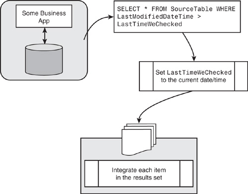
Date/timestamp fields are quite common elements of an application’s database design today. If your application table does not have a modified date/time field, you may be able to add one, but this will generally require application modifications, database triggers, or both.
Make sure the date/timestamp includes time information (not just date).
This pattern is subject to a few different reliability problems (outlined later). If the synchronization will be done only one way, one of the issues is avoided. Integrations that use a modified date/timestamp are therefore best suited for one-way environments (and not two way).
Pattern 3 Pros
• Supports multicast of changes to multiple systems, because the bind variables can be tracked independently for multiple source queries. Each of the distinct integration processes must maintain the date and time of its last query execution.
• Setup is simple if the application tables already include a modified date/time field.
• This pattern can be used with any application API, or data source that supports filtered queries, without requiring a direct connection to the SQL database. This makes this pattern generally useful in on-demand application environments.
Pattern 3 Cons
• This pattern might not be completely reliable for two-way synchronization processes. To prevent bounce-back, an “ignore user” filter needs to be implemented. Many applications that have a modified date/timestamp often include a ModifiedBy or ModifiedUser field, too. This field can be used to ignore updates that bounce back but can result in missed updates. When one user makes a change, and the “ignore user” filter changes the same record before the source query detects the change, the first change is ignored.
• This method presents significant challenges with clock synchronization if the ModifiedDate field is not set using the clock of the source database server (or application server, if appropriate).
• This pattern requires you to build additional functionality to support retry of rejected records against the target application.
• This pattern typically does not support deletes. If the application performs “soft deletes,” deletes may be accessible. However, deletes can be unreliable in this case because the cleanup of soft deletes is usually unpredictable.
• Source queries can get complex if you are tracking changes on parents and children together (joining them as one result set). In this case, the modified stamps on the parent and child records need to be checked.
Pattern 3 Implementation Tips
Integration processes that use this pattern must include a mechanism to capture records that are not successfully processed against the target application for retry. This can be accomplished by either processing records through a message queue or maintaining a rejected row table or file.
Be sure the Modified field includes both date and time. (If only the date is available, the frequency of synchronizations cannot be greater than daily.)
Be sure the Modified field is database (or application) server-based. Sometimes the modified stamp field will be set using the clock on the network client computer, and this will cause significant problems when changes are made by clients with clocks that are out of sync. If the application supports remote or intermittent synchronization of laptops, sometimes the modified stamp field is the time entered or modified on the remote laptop. To capture changes accurately and reliably, this field must be set using the server clock.
Your source query relies on maintaining the date of the last time the query was run. Right before executing your query, get the date/time from the same database or application server clock used to set the modified date/time for use in your next query.
For better performance, be sure that the modified date/time field is an indexed field within the database. If it is not indexed individually, but only as part of a multisegment index, make sure it is the first segment (in at least one index).
If you are implementing a two-way synchronization, investigate whether the updating of the modified stamp field can be suppressed for changes coming from other applications. If so, a ModifiedBy field is not required to prevent bounce-back, and the missed updates problem will be eliminated.
If capturing changes to parent and children records together (header and line items), check to see whether all child required record changes result in a change to the parent modified stamp. If so, the parent stamp can be used exclusively.
Pattern 4: Snapshot Comparison
This pattern uses an exact replica of the source application’s data set to identify changed records. By comparing a copy made at point A in time with the latest source data at point B in time, changes between point B and point A can be identified (see Figure 17.17). This process needs to compare all source data row by row and field by field, to identify new, modified, and deleted records. After those changes have been identified, a new replicated copy of the source data is made to be used as the point of comparison for the next time the process is run.
Figure 17.17 Typical snapshot comparison scenario.
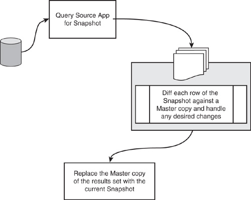
This pattern can be used by querying the source data directly, or by processing data that has been exported to a file or staging table.
Pattern 4 Pros
• This pattern can be used with almost any data source. Special system and application requirements are minimal. This approach works equally well when accessing source data directly and when processing an extracted copy of the source data.
• This pattern can be used with any application API or data source that supports ordered queries and does not require a direct connection to a SQL database. If the data source does not support ordered queries, the data must have been presorted.
• This pattern is not prone to the missed update problem that can occur when filtering on user to avoid bounce-backs.
• Supports reliable delete detection.
• Processing can be timed or sequenced to prevent dependent record sequencing issues.
• If a change is made to a source field that is not included in the integration, no processing is performed. This reduces the number of no-change messages that are processed, and thus reduces the potential for update conflicts.
• Header and line-item records can be grouped together into one message (and one comparison) to detect any changes to the group, and generate a single header and line-item message or transaction.
• This mechanism is reliable and ensures that no changes are missed.
Pattern 4 Cons
• This approach can be complex to create, involving significant coding.
• This approach is an inefficient way to detect changes and can take many minutes of processing to find just a few changes.
• Because of the long time required to process all source records, the frequency support is low (usually only daily).
• This pattern does not include any mechanism to prevent bounce-back. Therefore, all changes originating in the target system will make a complete cycle back to the target system. However, the cycle will end there, even if this same net change pattern is used to synchronize changes from the target system. The bounce-back messages can cause update conflict issues when competing changes happen in a short time frame and in a specific sequence.
Pattern 4 implementation Tips
The processing time required, and the inefficiency of this approach, is determined by the number of records in the source and the percentage of records that typically change within the scheduled time. To maximize the efficiency of this process, this pattern requires that the source result set be ordered by a unique key field (or set of fields). The snapshot data can then be retrieved from the shadow tables in the same order, and the result sets are traversed in lockstep.
Which Net Change Pattern?
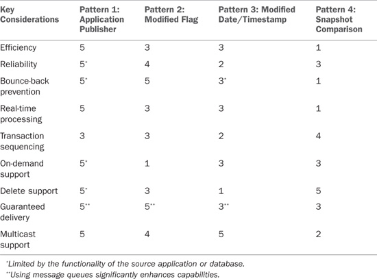
The best net change for any project is determined by a number of factors, including the overall integration requirements, available skill sets within the company’s IT organization, and the limitation imposed by the applications involved. Table 17.2 summarizes the four patterns discussed in this chapter and how they stack up against the key design considerations, with 5 being the most and 1 being the least. In most real-time, bidirectional integration scenarios, the application publisher pattern is clearly the preferred method but may not be useful given that very few applications support these capabilities today. Support for this pattern is growing within contemporary, packaged business applications and should be strongly considered if it is available.
Table 17.2 outlines key net change considerations.
Table 17.2 Key Net Change Considerations
Summary
This chapter covered methodologies and approaches available when using Scribe integration components (specifically migration, synchronization, and process integration options).
We reviewed both the main features of Scribe Workbench and Console, and worked through a number of integration and migration examples. Then, we covered the key concept of net change (and looked at several examples).
It is important to note that this chapter illustrated the high-level components of data integration (both in approach and concept) but is by no means exhaustive, and your specific business needs may well exceed what is outlined here.
