
5 Renewable Energy Sources
Kamal Kant Sharma, Akhil Gupta, and Akhil Nigam
Contents
5.2 Classification of Renewable Energy Sources
5.1 Introduction
Frequently, renewable energy (RE) is referred to as clean energy or green energy, making use of natural resources like solar orientation or rotation, or wind flow at a particular speed [1, 2]. Renewable energy is a freely available energy which is extracted from all natural resources which are present in abundance like solar orientation (which normally people frequently misinterpret as sunlight), rotation of wind (clockwise or anticlockwise direction), and using the gravitational effect of the moon towards the earth in bringing heavy tides every 15 days [3–5]. Renewable energy also involves differences in the earth’s crust temperature in the uppermost layer in the form of geothermal energy, which can be connected to meet local and global loads. These sources, cited as renewable energy sources, are replicable, consistent, and readily available. Another advantage of renewable energy is its use as a dispersed resource for a connected power system.
In the past century, there was less knowledge about renewable energy sources (RES), but, as time passed, people began to understand about the generation of electricity through various RESs. With the usage of fossil fuels, like gas, coal, and oil, there are problems like hazardous gas emissions, high noise, poor reliability, and low efficiency. These non-RESs can endanger human and other life, and cause serious problems. All the RESs should be introduced by bearing many considerations in mind, because every source performs well under certain climatic conditions. Properly selecting the appropriate RESs at a particular location can provide efficient and sustainable energy. Following depletion of the ozone layer with the release of chlorofluorocarbons and halons from refrigerants and aerosols, the Kyoto Protocol was signed among developing and developed countries to save the environment by stopping the emission of harmful gases. As a consequence of this agreement, most of the countries which were not using renewable energy sources agreed to use those sources on a large scale, keeping in consideration energy demand and the type of source suitable for sustainable development.
The main reason to develop a framework for renewable energy sources is to provide immediate power and customized load (“demand”) benefits. Many utilities and companies started providing in-house facilities to organizations to use RESs in a better way, to optimize their productivity and reduce carbon footprints. One of the major benefits of using RES is to provide electricity and carbon credits (which can be sold at a considerable price in the international market). Due to these benefits, many countries started promoting the usage of RES, providing different subsidies for the same. Dispersed generation, another form of energy generation, developed with changes in environmental indices, resulting in reduction of harmful gases [6, 7]. Sources of energy and their impact are qualitatively analyzed on the basis of three parameters, namely security, cost efficiency, and environmental sustainability. For over a decade, industries and communities have been working on alternative forms of energy and making them more useful in terms of localized power generation and increased capacity of alternative resources to generate electricity comparably to conventional energy sources, with transmission-distribution losses and less capital investment, resulting in a new emerging field, renewable energy sources (RES) [8].
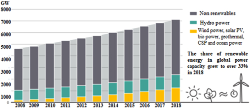
Every emerging energy technology is based on two concepts, energy efficiency and environmental sustainability. Clean and green energy sources, in terms of sustainability, include direct or intermediate sources such as photovoltaic or wind energy (which is also a by-product of the solar system, as a result of temperature variations at the Earth’s surface). Energy-efficient technologies, which build up energy efficiency, include virtual power plants, smart meters, and combined heat-power. These requirements are included in clean energy technologies [9]. Renewable energy (RE) is also dependent on hemisphere location and particular areas in terms of temperature variations. Wind generation is relatively uniform in coastal regions but, on the other hand, solar photovoltaic energy depends on solar orientation, such as sites in the southern hemisphere (or mountain-based areas). As we qualitatively analyze different sources of energy, these sources are often shown to be area specific, with investment needed changing according to selected requirements. These sectors need RE to perform under different criteria to provide efficient energy. The contribution of RE to power generation continued to expand strongly from 2012 to 2018, as depicted in Figure 5.1. Approximately 181 GW of electric power is generated in 2018 in Japan, which grows annually at 8%, making a projected total capacity of 2,378 GW globally by the end of 2018.

Greatly increased amounts of power are being generated through different RESs as compared with previous years. Globally, the hydro-power still accounts for about 60% of RE production in 2018 and is followed by wind power (22%), solar photovoltaic (SPV) (10%) and biomass power (9%). Energy sources have evolved in different aspects but, since its inception, RE has not been able to expand globally and make its presence felt in every country. The main reason for the low impact of RE globally is the presence of different temperature gradients and the location-specific nature of some RESs, although some sources are limited and can be considered only as peak sources, without 100% utilization. With under-utilization of RES, the load factor is not 100% and is unable to make inroads into into the conventional power system, resulting in limited RES usage, with particularly low impact in countries of the Asian continent.
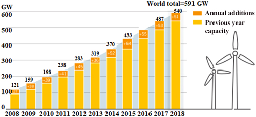
Another major reason for the slow adoption of RES is the large capital investment undertaken in fossil fuels and correspondingly the relative lack of investment in the case of RES. Across the globe, countries are segregated into developing and developed countries. Developed countries signed the Kyoto Protocol with developing countries, to reduce carbon footprints and to reduce the risk of global warming. Despite this, developed countries, representing 35 out of 130 counties, with an installed capacity of 10 GW, are increasing their continuous productivity with the enormous use of fossil fuels, with RE in developing counties being limited to only 1 GW, as a result of rural electrification. On the other hand, in remote locations in developing counties, where access to conventional power systems is minimal and load centers are of limited capacity, implementation of RESs is easily carried out; annual increases every passing year are depicted in Figure 5.2 [10]. The European Union and islands with small capacity are converting from conventional energy to new alternative sources of energy, involving clean energy mechanisms, with solar photovoltaic (SPV) integration or microgrid (non-conventional grid), with more integrated resources connected with SPV.
5.2 Classification of Renewable Energy Sources
There are several RESs through which electric power can be generated, namely SPV, wind, hydro, and biomass. All these RES perform under the influence of different environmental conditions. Typical parameters of changing climatic conditions, on which the performance of these RES depend, include ambient temperature, wind speed, availability of run-off, solar radiation availability, and cooling conditions. This chapter highlights various avenues with which to generate electric power through available RESs, which are described below. It also reports the systems responsible for energy conversion, along with the associated technologies implemented.
5.2.1 Solar energy
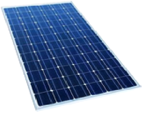
Of all the renewable energy sources available, SPV is the most tested and most abundant source available but its utilization is dependent on many parameters. It is preferred because of its fast response, high generation efficiency, and low maintenance costs. Basically, sunlight is directly converted into electricity through a non-linear semiconductor device. An SPV cell is made up of a semiconductor material, which converts sunlight into electricity. These materials are classified into three types, according to their efficiency and availability. Materials are categorized as film structures and layers of materials like single crystals, multiple crystals, uniform and non-uniform crystals with structured and non-structured arrays [11, 12]. Various crystal structures include mono-, poly-crystalline, and thin film or amorphous film used in different configurations, with different integrated circuits and voltage levels. Every installation requires different materials based on its operating function. Globally, demand for solar energy is increasing from both the consumers and the utilities.
Across the globe, the total amount of power received from the sun in the form of diffusion, emission, or dispersed power is estimated to be around 86000 TW, which could light the world without any use of conventional energy sources or the emission of harmful greenhouse gases. With advances in technology, different ways of generating electricity from solar energy have been classified into concentrated medium or solar photovoltaic medium. Energy is the by-product of each of these two processes, and the mechanism used for generating electricity arises through either the concentrated process, at a temperature of around 35°C, or via the solar photovoltaic (SPV) method, where generation is controlled by solar cells.
Projections are being made by different organization about the increase in generation of power by SPV to a value of 28% of global demand by 2050, as reported by the IEA (International Energy Agency) in their annual report in 2019, tabled at the annual board meeting. It is also expected in the report that the share of energy generation by SPV plants would increase from 10% to 16% by 2050, with 12% of that power being generated by concentrated power plants connected to the microgrid. Despite advances in the field of installation and implementation of modules for solar power generation, SPV module efficiency is limited to 16–25%, depending upon the type of material and its structure. Limitations in the SPV module are also associated with mono- and poly-crystalline materials, along with the direction and orientation of Sun. The SPV module also works in accordance with seasonal variations and dependence of the energy generated on the frequency of the light. Due to this dependence, semiconductor materials are used, as they behave like insulators at room temperature but, as the temperature rises and the materials have negative temperature coefficients, the semiconductor materials start to conduct. Due to this partial behavior, semiconductors like silicon or arsenide absorb photons of light and produce electrons to contribute to the flow of current. If an electron absorbs the energy of one photon, it requires more energy than its estimated work potential to release energy via the photoelectric effect. The SPV module also has drawbacks in the need for huge capital investment, as an installation of 1 KW is able to supply only 5 units of energy on a daily basis [7].
Solar emission and radiation are the most common methods to convert solar energy into potential sources of energy; however, solar energy is easily transformed into thermal vibrations, with the prime mover changing stabilities for conversion to electrical energy by means of a generator. The use of a generator is problematic as it involves many intermediate processes and the efficiency reduces significantly as a result, its performance depending upon the type of material used. Although many kinds of materials are available in the form of hybrid, mono- and poly-crystalline structures, the performance is still limited, and output is DC voltage, requiring a sophisticated system for conversion to AC which also introduces harmonics. Solar radiation is commonly used in SPV and incorporated in chemical and biological use as a catalyst at a specified temperature and at a particular solar orientation. SPV (solar photovoltaic) is itself a hybrid process and used for cooling and heating in remote and urban areas. It is quite environmentally friendly and economically efficient, requiring fewer installations, and certain state governments in India are offering subsidies to promote it in residential and public utilities. Especially in the northern part of India, SPV are mandatory for houses larger than 1000 sq. yards. Due to their lower efficiency, SPV systems were rarely used but research has progressed, with new materials and advanced conversion technologies. As a result, SPV has been developed as a new potential source of energy, catering for the demand of consumers, where conventional systems failed to provide the minimum electrical supply required. It is expected that, by 2030, SPV would cater for 40% of the total consumer demand in India, in areas which do not exhibit heavy demands for electricity.
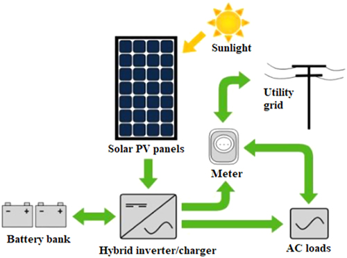
There are different sizes of SPV cells available. The shape of the SPV cells may be square or round. Particular shapes are preferred, depending on the installation, as required. The SPV system consists of various components which together generate electricity. They are SPV cells, SPV module, SPV array, battery bank, charge controller, combiner box, and meters for instrumentation [13].
- SPV Cell: The SPV cell is a very small unit of the system. Every cell is made of a p-n junction semiconductor; in other words, it consists of a semiconductor in the form of silicon, involving the loss and addition of electrons. Every semiconductor is an insulator at room temperature, and the mobility of electrons is characterized by losing and gaining electrons in consideration of electron affinity and ionization energy. Silicon with fewer electrons but more holes and is termed as p silicon whereas silicon having more electrons is termed n silicon. A mixture of both p- and n-type silicon makes monocrystalline cells, whereas when two different materials are combined together to form a p-n junction, they are described as a non-crystalline or poly-crystalline material. Due to this combination of holes and electrons in a junction, the depletion layer is created with the energy potential, which keeps changing, depending on the biasing of a junction. For example, if a junction is forward-biased, then its width reduces, with the opposite happening in the case of a reverse-biased condition. This biasing represents the polarity of supply connected with the semiconductor materials, as the same polarity is considered to be forward biasing whereas reverse biasing is of opposite polarity, connected with the supply and junction. Biasing needs to be understood from the junction point of view, with p-type representing the positive supply (holes) and the n-type representing the negative supply (electrons) [1]. Due to this combination of junctions, I-V characteristics are determined; in the literature, V-I characteristics are also mentioned, which is the relation between load current (output current) and terminal voltage (voltage at terminals) of the cell at a specified temperature. These characteristics signify the rating of a cell at solar irradiance (solar orientation) and number of cells connected is calculated from the voltage and current behavior (Figure 5.3).
- SPV Module: The module represents the basic structure of a system connected together in series; it consists of many solar cells connected together, with the connected solar cells being wired and assembled together with the help of wires, and every basis wire being connected in parallel with strings. Therefore, the SPV module is a combination of solar cells with increased current rating but with every cell connected together with strings which are in parallel together. As a result, the SPV module is a series-parallel circuit combination of solar cells with the same I-V characteristics (Figure 5.4).
- SPV Array: As the name suggests, this is an array or collection of solar cells connected together, strengthening the current voltage characteristics. Modules consist of solar arrays connected in series to increase output terminal voltage, whereas a solar panel is connected together to form an array. An SPV array is required to generate sufficient electrical energy, with a combination of solar cells connected together, to provide a requisite output. In other words, for a solar cell, the solar array is an output which is further connected with conversion technologies to form a regular combination for the desired voltage and current output. SPVs are connected in a form of array for large installations, where they are connected in series or in parallel, depending upon the voltage or current requirement. For higher voltage, less load current, and less specifications of real power, series connection is preferred, whereas, on other hand, if the load requirement is greater with the minimum voltage or a constant voltage, then a parallel connection is preferred for a solar array (Figure 5.5).
- Battery Bank: In case of a SPV, the battery bank is an optional requirement in case the consumer wants to store excess electricity generated. This kind of SPV is classified into a stand-alone system or an islanded system. In the case of hybrid systems, where all sources are connected together, and the load flow analysis is carried out, then the battery bank is required and the SPV can be used as a peak power plant. If excess energy is not generated per installation, then a battery bank is not required. The main function of the battery bank is to supply electric power at intermediate and intermittent times. The main specifications of a battery bank involve discharge rates, type of material used, durability, efficiency, and ergonomics. A battery can also be classified into different categories, depending upon the system incorporated.
- Charge Controller: This is a microcontroller, which decodes the battery performance and reduces the gap between charging and discharging of the battery. It can be customized, depending upon the battery specification and the type of load connected with the SPV module.
- Combiner Box: This is protective equipment connected with the SPV modules and away from the installation. It is used in cases where various SPV modules are connected and routed with different channels. The combiner box involves single-conductor pigtails, with connectors already connected, with modules of smaller and larger capacity integrated. It also consists of a protection box for every string connected in parallel with the SPV modules.
- Meter and Instrumentation: Metering is an important aspect in SPV modules as they are available in off-grid and on-grid metering and available in two types of meters, namely the utility kilowatt-hour meter (for payment module) or the system meter (for calibration). These meters measure and display the performance of SPV systems, like battery charging and electricity used (Figure 5.6).


5.2.2 Wind energy
Among RES, wind energy is the second most important source of electric power. This system converts wind energy into mechanical energy, which is converted into electrical energy through the use of turbines. Wind energy is attaining increasing importance worldwide, as the processes of industrialization and economic development demand improved energy production. Wind energy requires no external source; it is free. Wind energy is an intermittent source of renewable energy and therefore the power generated by wind turbines and wind farms varies, due to variation in wind speed. As a result, the performance of a wind energy system changes as a result of variation in wind speed. This system involves two types of generators which work at either constant or variable speed. Hence, the efficiency of these two types of system is different [8]. The location and installation of a wind energy conversion system is to generate the electric power near to the connected load of consumer. There are some parameters which define the performance of the wind energy system. Wind energy exceeds every other renewable energy source due to its ergonomics. As a result, wind energy is growing in importance as it is available in abundance due to temperature differences, created by solar radiation on uneven surfaces and by the elliptical rotation of the earth. It can be used at remote locations, mostly remote coastal regions, which are not supplied by conventional energy sources and is of great importance due to its contribution to the economy of a region. Wind energy is quite environmentally friendly and has a load factor less than 100%, so that it acts as a peak power plant [7].
In Asia, the term “Green Energy” has had a great impact, and most of the countries are able to use it to boost their economy and take advantage of the Kyoto Protocol, in which developing and developed countries signed an agreement to boost green energy use, giving benefits to developing countries in terms of carbon credits, valued at US$ 14 per unit. India and China are in “rat race”, developing green energy infrastructure as both are human capitals of the world and emerging economies, with huge demand for electricity. In India, rural electrification stands at 10 houses per village, remaining at 40% non-electrification. In recent years, the Ministry of New and Renewable Energy (MNRE) has been constituted in India, with similar ministries in countries throughout the world. In terms of wind energy production, India stands at 4th position globally. Some of the important facts which need to be understood before evaluating the potential of wind energy are minimum wind speed and minimum turbine height (approximately 80 m), so that the wind energy can be extracted. To date, India has been able to capture the potential in some states, with enormous wind capacity along coastal pitches. There are many hurdles to be overcome with respect to wind energy, as different types of generators are required in terms of generating electricity but due to absence of sufficient sources of reactive power compensation, control systems for pitch angles and accepting density of wind (in terms of catchment), it is sometimes difficult to control the variable output as the connected load varies.
Some of the regions in India have installed wind power plants and various companies have also invested in large numbers of turbines, due to exponential demand, but still many outcomes have been blocked due to technological roadblocks. One of the major roadblocks is interference from local governments in providing infrastructure and land, the latter being a major requirement for wind farm installations, but it is predicted that, with the formation of MNRE, states would be integrated and feasible solutions would be achieved. Considering the global scenario, major developments in wind power technologies was initiated in 2017 in India, with off-shore and on-shore technologies being established in 2018, with advances in microgrid development. With respect to on-shore wind energy generation, energy is generated in bulk and directly without any intermediate processes, but off-shore generation involves transmission of the energy generated through intermediate processes, with the efficiency reduced to 15% which is unacceptably low. In India, off-shore wind energy development potential is large but worldwide, a 4% decrease in off-shore wind energy generation has been observed in recent years (Figure 5.7).
Major factors which impact the performance of wind energy systems are:
- Variable wind speed operation of generators to generate maximum energy,
- Advances in power electronic devices for wind energy,
- Improved power plant operation and efficiency [14, 15],
- Better economics, due to the presence of large wind-generating plants.
The following are the components of a WPP (wind power plant), along with their roles and limitations:
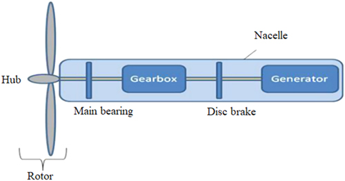
- Nacelle: This is basically a combination of components connected together at the top of the wind turbine, can be seen in top-view projections of a plant, and includes wind turbine subsets. Nacelle, as the name suggests, connected various components of a generator, with the controlling mechanism, including output and input transitions of a different nature. It also includes power electronic interfaces with values required to drive a generator with sufficient amount of reactive power injected into it. The main role of the nacelle is to maintain uninterrupted motion of the wind plates in a direction so that optimum rotation to achieve maximal power can be obtained [11] (Figure 5.8).
- Rotor: The rotor picks up the wind energy and passes it on to the drivetrain. The rotor hub is a component which connects the rotor blades to the rest of the system and delivers the power to the rotor shaft. The position of each individual rotor blade, with respect to the wind, can be controlled using so-called pitch motors (Figure 5.9).
- Tower: This is the largest and heaviest part of the wind turbine. The higher the tower, the lower the loads due to turbulence, resulting in higher wind speeds. There are different types of towers, such as tubular steel towers, lattice towers, and guyed pole towers.
- Turbine: Turbines act as a low-pressure to high-pressure mechanism, working opposite to a nozzle in such a way that its operation is similar to a prime mover which drives a generator at a particular speed to generate electricity. In a wind power plant, the input of the wind turbine is variable and wind speed is not constant, so the importance of the wind turbine increases significantly and is classified on the basis of operation and requirement. Rotation of the turbine depends on the axis of the wind, designated as horizontal or vertical, so that the turbine needs to be connected perpendicular to the axis to achieve its maximum output, with the wind turbines being designated as horizontal or vertical axis turbines Wind turbines can be divided according to the orientation of the axis of rotation, such as horizontal axis and vertical axis turbines. The two turbines are different in nature, with different terminologies, with horizontal turbines requiring a tower and a nacelle at the top, and requiring skilled manpower for installation and handling of large amounts of wind speed. These kinds of turbines are costly in nature and the number of blades is variable, depends upon the requirements and centrifugal forces dynamics. Mostly, the number of blades is limited to three, as increasing number of blades will reduce the efficiency of the system; the more complex in nature, the greater the reactive power requirement and the less the voltage control. On the other hand, vertical turbines are less costly and are simple to construct but handle very less wind and are used as off-shore wind power plant; they are limited to low power generation at remote places with considerably less manpower. Vertical turbines have lower conversion efficiency and are used only with lower blade effectiveness (Figure 5.10).
- Generator: There are different types of wind generator, the effectiveness of which depends upon the speed. They are referred to as fixed-speed induction generators or doubly fed induction generators.
- a) Double-fed induction generator: Double- (doubly) fed induction generators involve feeding at both ends, with excitation as an external source parameter. This type of generator is variable and can be customized; it is non-synchronous in nature as active and reactive power controls can be performed by changing the frequency of a system and by partial voltage control at the rotor side. With a change in excitation, the field changes and, by changing the field above and below the power factor, efficiency can also be affected. These operations of the generator can be studied through the V-curves of synchronous machines, with changing field excitation. As an induction generator, the operation also depends upon the value of slip; it will work only if the value of slip is negative, with reactive power flowing. This kind of generator comprises of two parts: the stator and the rotor, where the stator is connected with the grid but, in other rotor operations, is controlled by excitation and driven by changes in speed and frequency. Moreover, these generators are used primarily because of their range of speeds, which provides a range of generators with variable frequency and speed, and customized for different plants with suitable compensation (series and shunt) (Figure 5.11).
- b) Fixed-speed induction generator: Wind power plants are subjected to induction generators − fixed or variable. The fixed-speed induction generator follows the same operation as the doubly fixed but is of a squirrel cage type and is considered to be robust. Its speeds are not controllable and it is used for low levels of power generation at a constant input of wind speed. This kind of generator is cheap and easy to install, but its efficiency and survival rate is low, due to its lack of ability to withstand fluctuations in load. Another major drawback is its inability to control reactive and real power, an external source being required for compensation, which is quite costly due to its specifications and its low availability (Figure 5.12).
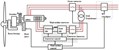
FIGURE 5.11 Schematic of a typical doubly fed induction generator 
FIGURE 5.12 Schematic of a typical fixed-speed induction generator


5.2.3 Hydro-power
Hydro-power is commonly regarded as a conventional energy source but a hydro-power plant can also be classified as a non-conventional energy source, with a run-off river power plant, with or without pondage. Hydro-power plants used as renewable energy sources are not able to sustain a load factor of 100% and are categorized as peak power plants, with indices of real and reactive power. Hydro-power plants convert potential energy to kinetic energy, using different types of turbines classified on the basis of their heads. Hydro-power plants use different heads and require specific turbines to act as a prime mover for synchronous generators. In a hydro-power plant, low-speed synchronous generators, with salient types of heads, are used in a vertical position, with the water falling from the vertical side. This kind of power plant consists of a reservoir, dam, and catchment area, and serves a large, dispersed population [11]. Different types of heads are maintained, depending upon the capacity of the generator, and to prevent the dam from excessive water, different types of gates are available and are termed spillways. Hydro-power plants cater for peak demands and base demands of generation and are monitored through real-time scaling. In India, hydro-power plants cater for 40% of total demand and globally they meet 60%, with an estimated capacity of around 1,132 GW.
Since 2017, India has increased its installed total capacity by 1% and commission of plants by 0.5%. By the end of 2018, India had increased its hydro-power capacity to a total capacity of 45.1 GW. There are advantages of hydro-power such as its being environmentally friendly, with high flexibility, and low operational and maintenance costs, whereas disadvantages are its dependence on rainfall, and the high capital costs and the remote locations of hydro-power plants. Important components of a hydro-power plant are illustrated and explained below:
- Dam: The dam plays an integral role in constructing a hydro-power plant with different heads, forming a reservoir and controlling the water, when needed. There are different kind of dams available, which are classified on the basis of area, construction type, and capacity to be created, known mainly as rock-fill, earth-fill, and masonry dam. Masonry dams are very few in numbers and are located only near deltas, whereas rock fill dams are robust and can have a large capacity in terms of energy generated, with earth fill dams being semi-built, with underground dams. It is essential to maintain the dam, with spillways provided to release the build-up of excessive amounts of water.
- Water reservoir: The reservoir is a part of the dam, which stores the water in a rainy season, providing it, whenever required, with a help of surge tank if excessive water has to be pumped out. The reservoir is the main bank, where water is to be released for making different heads, so that the height of the reservoir should be more than the height of the dam, with water held by the dam. The dam height is also used to measure available potential energy of the water stored to be used for generation of electricity.
- Trash rack: This is a preventive measure to remove any unwanted material from the water released from the reservoir to dam. Its main function is to prevent blockage of nozzles and turbines with such material. Most hydro-power plants with different heads use a reaction turbine, but some of the plants use an impulse turbine where the pressure on the water needs to be the same on both sides of the dam; debris can destroy an impulse turbine and also keep water in its liquid form when the temperature is low.
- Forebay: This is basically a regulatory mechanism, which involves a surge tank to control the flow of water, taking into account the value of the load. If the load is suddenly reduced, then generation of electricity has to be slowed down but water intake has already been carried out; therefore water regulation is used in the form of forebay so that penstock, the channel which carries most of the water, is not destroyed.
- Generator: Different types of generators are used for hydro-power plants, and are termed synchronous generators; the generators need to be of the salient type to keep the transient reactance constant throughout, and used with low-speed capacity to generate electricity. They are connected in a vertical formation, having real and reactive power ratings associated with the control mechanism.
- Penstock: This is a channel for carrying water from the reservoir to the processing unit. In this case, the processing unit involves the generator, turbine, and intermediate processes, and the outcome is the generation of electricity. This is a shaft sometimes used to bring water from the reservoir to the processing unit through a zigzag route in which a pumped motor is required to speed up the water flow to the end of the water turbine. To prevent the need for a penstock, the surge tank is connected to maintain the overflow of water back to the reservoir, which can otherwise damage the penstock. The penstock is a wide channel, which can be opened for maintenance in earth-fill plants.
- Water turbine: The turbine plays an integral role in a hydro-power plant for electricity generation. The turbine is the most expensive and important component. The turbine is the heart of the system, converting potential energy into kinetic energy and acting as a prime mover. Depending upon the use of different heads, turbines are classified as impulse or reaction turbines. Impulse turbines are used with fixed heads, whereas impulse turbines are used with variable heads. In the case of reaction turbines, they are classified as Pelton, Kaplan or Francis turbines, which are selected in order to generate optimum output. Water flows from the penstock channel to the turbine and, after the designated operation, water flows down with help of the tail race so that the turbine should be free from moisture, and the blades should be mechanically strong and free from friction, and can be used for longer periods of time.
- Transmission lines: The main work of the transmission network is to transmit electricity to end-users, keeping in mind the protection level and ergonomics. Transmission lines can be categorized as long, medium or short transmission lines, depending upon voltage level and the length connected. Certain parameters are involved to maintain the configuration of the transmission line, following its ABCD parameters and delta star operations.
5.3 Conclusion
RESs are predicted to play a vital role in power production for many years. These RESs employ advanced technologies, provide faster response and achieve greater efficiency. Globally, reports have shown the total estimated capacity of all RESs worldwide. These RESs are expected to play a significant role in development of the installation of smart grids, thus paving the way for supplying good quality electric power to consumers. Obtaining good quality electric power will greatly enhance the confidence of industrial players to contribute more in building infrastructure which can greatly help in further enhancing the economy.
References
- 1. C. Wang, and Yuefeng Lu, Solar Photovoltaic, Bachelor thesis, Savonia, p. 35, 2016.
- 2. M.M. Rahman, S. Salehin, S.S.U. Ahmed, and A.K.M. Sadrul Islam, “Environmental impact assessment of different renewable energy resources: A recent development,” Clean Energy for Sustainable Development, pp. 29–71, 2017.
- 3. P.R. Varun, I.K. Bhat, and I.K. Bhat, “Life cycle greenhouse gas emissions estimation for small hydropower schemes in India,” Energy, 44(1), pp. 498–508, 2012.
- 4. R. Bertani, and I. Thain, “Geothermal power generating plant CO2 emission survey,” IGA News, 49, pp. 1–3, 2002.
- 5. F. Blaabjerg, and K. Ma, “Renewable energy systems with wind power,” Power Electronics in Renewable Energy Systems and Smart Grid: Technology and Applications, edited by B.K. Bose, John Wiley & Sons, Inc, pp. 315–345, 2019.
- 6. REN21, Renewable 2019: Global status report. Secretariat Renewable Energy Policy Network for the 21st Century (REN21) Paris, 2019.
- 7. S.M. Islam, C.V. Nayar, A.A. Siada, and M.M. Hasan, “Chapter 1-Power electronics for renewable energy sources”, Alternative Energy in Power Electronics, Butterworth-Heinemann Elsevier, pp. 1–79, 2011.
- 8. P.S.R. Murty, “Chapter 24-Renewable Energy Sources”, Electrical Power Systems, Butterworth-Heinemann Elsevier, pp. 783–800, 2017.
- 9. W. Strielkowski, “Renewable Energy Sources, Power Markets, and Smart Grids”, Social Impacts of Smart Grids, pp. 97–151, 2020.
- 10. B.K. Sahu, “A study on global solar PV energy developments and policies with special focus on the top ten solar PV power producing countries,” Renewable and Sustainable Energy Reviews, 43, pp. 621–634, 2015.
- 11. H.J. Wagner, “Introduction to wind energy systems,” EPJ Web of Conferences, 54, p. 01011, 2013.
- 12. I. Dincer, “Renewable energy and sustainable development: A crucial review,” Renewable and Sustainable Energy Reviews, 4(2), pp. 157–175, 2000.
- 13. E. Fertig, and J. Apt, “Economics of compressed air energy storage to integrate wind power: A case study in ERCOT,” Energy Policy, 39(5), pp. 2330–2342, May 2011.
- 14. W.B. Lowrance, and H. Dehbonei, “A versatile PV array simulation tools,” presented at ISES Solar World Congress, Adelaide, South Australia, 2001.
- 15. A.K. Aliyu, B. Modu, and C.W. Tan, “A review of renewable energy development in Africa: A focus in South Africa, Egypt and Nigeria,” Renewable and Sustainable Energy Reviews, 81(2), pp. 2502–2518, January 2018.