9 Electric Energy Systems
Kamal Kant Sharma, Akhil Gupta, and Akhil Nigam
Contents
9.2 Classification of Energy Sources
9.3 Components of Electric Energy System
9.3.3.2 Compressed Air Storage
9.3.3.3 Flywheel Storage System
9.3.3.5 Super-capacitor Energy Storage
9.3.3.6 Super-conducting Magnetic Energy Storage (SMES)
9.3.3.7 Electrochemical Energy Storage
9.1 Introduction
The needs of society and the dependence of gross domestic product (GDP) on reliable performance parameters for the production of electrical energy have increased exponentially. The main reason for this increase is the enormous use of electrically enabled devices and the “rat race” between developing and developed countries for a share of the profits from industry. The energy system is also making progress in the production of electricity by employing advanced technologies with a focused effort to make the system more reliable and sustainable. For more than a century, the electric power industry has developed across the whole world, with the introduction of different energy production sources [1]. There are basically two types of sources, namely conventional and non-conventional energy sources.
Conventional fossil fuel-based technologies, which have dominated electricity generation for decades have many drawbacks and various limitations, such as greenhouse gas emissions, pollution and the destruction of aquatic life, and the global impacts on climate change. Conventional power plants are installed in a centralized system and distribute electrical energy to different parts of the country, depending upon revenue and per capita consumption. The centralized structure enables the supply of electricity to sites which are far away from a generation site and requires a high-voltage insulated network. These conventional plants are suitable for large-scale distribution, but, for smaller scale generation and supply, distributed generation is used, known as a customized power plant [2 –4]. These latter interconnected networks install various components like busbars, transformers, circuit breakers, and relays to transmit electricity efficiently. Sometimes, due to the presence of various losses, due to faults, there may be some loss of efficiency. CO2 emission from fossil‐fuel power plants also reduces the efficiency of electricity generation from power plants. Hence, these power plants need modern solid-state electronic devices or smart devices, together with advanced technologies, which play a crucial role in reducing these losses and which control environmental pollution, to achieve greater efficiency.
Various observations have been analyzed from current scenarios, considering a mismatch between demand and supply of electricity at the customer’s site. There are many problems facing the growing power industry to meet the gap between the existing supply and distribution structure and what is required. Currently, the electrical power industry is facing some unprecedented challenges and opportunities. The industry is entering an era of significant change through the introduction of advanced technologies, electricity market changes, new consumer behavior, and regulation. The existing electric grid also needs to meet higher standards, such as with respect to reliability, security, efficiency, sustainability, and service cost.
More importantly, in the 21st century, societal needs have become very different from those observed a few years ago. Better quality, greater reliability, increase sustainability, and greater efficiency have all become basic consumer needs for improved electric power and storage systems. In traditional times, these were available in a less amount because of a scarcity of resources [5]. Maintenance cost is also an important issue for the electric energy system. Due to the presence of hazardous conditions and faults, utilities are facing novel challenges. These challenges may occur from the consumer side, which need to be addressed to maintain the repair and upgrading of the necessary infrastructure [6 –10]. More advanced technologies and signal conditioning devices may improve these problems of overloading. These may also help to reduce maintenance costs and improve efficiency. All these difficult challenges require proper consideration from the regulatory authorities [11 –14]. Consumers must be acknowledged by being provided with full information regarding the costs and benefits of facilities, and the availability of the most appropriate infrastructure.
9.2 Classification of Energy Sources
Conventionally, there are two kinds of energy sources: primary and secondary. Primary energy sources are mostly suitable for direct use without any conversion from one form to another e.g. solar, wind, fossil fuel and natural resources [15 –17]. These sources are directly used for generating electricity but are limited in use; in the case of solar and wind energy sources, conventional systems cannot be incorporated directly due to the absence of reactive power and other types of generators, such as solar plate collectors and doubly fed induction generator (DFIG). In consideration of solar and wind energy sources, output from solar is only in the form of DC, whereas output from wind is variable and fluctuating in nature. Therefore, fossil fuels are still widely used, but coal-fired power stations produces flue gases due to incomplete combustion of fossil fuel, and these represent environmental hazards.
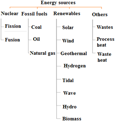
Major secondary energy sources are hydrogen and synthetic fuels. Another classification of energy resources is based on the time required to regenerate an energy source, such as renewable energy source [18, 19]. Renewable energy sources are not depleted by human activities. Sources which are renewable by nature, depending upon climate, include tidal energy, geothermal energy, biomass, and wind, as well as rainwater harvesting and waste management. It has been reported that 25% of total energy reserves are renewable resources, compared with70% of the reserves being coal-based [20, 21]. On the other hand, fossil fuels are dependent upon various human activities and day-to-day management of waste products and greenhouse gases. Figure 9.1 show classification of various energy sources, which are normally employed to generate electric power.
Greater dependence on fossil fuels and greater control of human activities would be difficult to embrace in the current situation. On the other hand, renewable energy resources which can be customized and connected nearer to load, known as distributed sources, could replace (at least in part) fossil fuels. Due to the increasing demand, distributed energy sources need to be connected with conventional sources but operational features are dissimilar from those of conventional sources, leading to fluctuation of voltage and changes in frequency. This kind of operational mechanism also leads to voltage instability and rotor angle instability under fixed conditions. Under dynamic operational conditions, practices of connecting conventional and distributed energy sources must be optimized with respect to environmental conditions, to ensure that all passive parameters obey maximum and minimum values of stability. These types of energy sources must be stabilized with compensation of the reactive power at the point of coupling in consideration of conventional and new sources of energy. This will improve the stability conditions and bridge the gap between load and supply with minimum disturbance [22].
9.3 Components of Electric Energy System
There are various components and power conditioning devices employed in electricity generating power plants under different conditions. These components must be flexible and reliable to achieve proper functioning of the system during the generation of electric power. Basically, there are three major functions of electric power systems: electric power generation, its transmission, and ultimately its distribution to consumers.
- Generation terminology explains the cogeneration (non-conventional) and conventional generation principles and makes use of renewable energy sources, along with conventional generation sources, such as fossil fuel, hydro and nuclear. Renewable energy sources acts as peak power plants with a load factor of less than 100% unity, whereas conventional power plants act as base plants, with the exception of the hydro-power plant segregated as a run-off river, pumped-storage plant or a storage power plant without pumped storage, depending upon its capacity and requirements.
- The transmission of electric power involves the capacity of the transmission line to handle the value of voltage, which needs to be kept high. The higher the voltage of the transmission line and the greater the insulation, the lower would be the losses. Transmission lines are also segregated on the basis of different voltage levels and assessed on the basis of certain parameters, such as ATC (available transfer capability), contingency analysis, and conductors formation. Transmission lines can also be segregated on the types of voltage used, namely HVAC or HVDC.
- The distribution of electrical energy is crucial as the most losses occur in this part of the power system. Distribution is done at the level of area, and segregated as mesh, radial, and ring power systems, depending upon the load requirements. These distributions are circulated through transformers and feeders via substations, comprising various electrical devices for protection, and auxiliaries for smooth operation. Substations are evaluated on the basis of a voltage drop of ±5% and segregated as indoor or outdoor substations. In hilly areas, H-pole mounted substations are used in order to compensate for the complexity in a system and the layout of power cables for distribution.
The most commonly used electric power generation network is shown in Figure 9.2. This depicts various components in which three-phase generation is accumulated by synchronous and non-synchronous generators. For protection, grounding terminology is used for individual components, whereas phase and line components are used for live connections considered neutral for safety (completion of circuit). Generation of voltage is done at multiples of 11, keeping sinusoidal waveform form factor 1.11 intact so that distortion and noise can be minimized, and regulated voltage can be obtained. The level of voltage from the generation point of view is variable and subjected to vary at different loads as the maximum voltage level of transmission is 765 kV and the optimum value of generation is 11 kV which generates minimum losses with maximum electrical capability of the system. The operational value of voltage increases with insulation level, consisting of various components, but mostly generation is accomplished by a three-wire system, having three phases, but, in the case of transmission, an extra conductor is provided at the top of the conductor, and is termed the earth conductor, and is required for safety. Remote generation is accomplished from distributed generation sources operating at the same level of utility voltage for achieving synchronization and being close to the customer site, and also known as cogeneration plants or stand-alone plants, if not connected with the main grid. Transmission capacity is governed by ATC or the maximum voltage-withstanding capacity of the line. Depending upon the type and level of voltage, layout considerations are implemented in the form of overhead or underground lines; underground lines incorporate cables whereas overhead systems require basic transmission layout at nominal voltage and current. The main constituent diversification of an electric power system is a distribution system which emphasizes voltage drop and feeder installation. In the case of a distribution system, the type of transformer decides the loading characteristics and efficiency of the system, and transformers used for step- down are segregated as core and shell transformers [21]. The segregation of voltage at the distribution end is limited to 400 V for industrial purposes and the agricultural sector, where load is intermediate and fluctuating in nature. Keeping voltage at a high value results in protection against electricity theft but safety considerations are of priority as consumers are involved in practices of distribution. Then, the operating voltage is stepped-down by using step-down transformers at a substation site to 132 kV, which is further stepped down to 34.5 kV for a normal distribution system. Eventually it is reduced to 230 V for domestic appliances and 400 V for industrial purposes [23].

9.3.1 Electric Power Plants
There are many industrial electric power plants, which play a major role in the generation and transmission of electric power. These employ sunlight (“solar photovoltaic”), wind, or hydro power sources which are converted into electricity through employing power converters, and which then transmit it. Sunlight is directly converted into electricity, whereas wind energy is converted into electric energy. There are two types of generation plants: conventional and non-conventional; Conventional plants involve fossil fuels, a resource available in abundance and ready to use for a long time period. As a consequence, these kind of plants can be located far from the consumer site and used in centralized power generation, whereas non-conventional (dispersed)generation involves intermediate energy generation, and supplements the conventional resource plant, requiring the assistance of converters and non-conventional generators, and having the disadvantages of reactive power compensation and voltage instability. These kinds of resources for electric power generation are segregated on the basis of the type of generation, the connected network, amount of generation, load factors, type of fuel used, and Kyoto Protocol indices. The main factor in dividing these resources into the two categories, based on the Kyoto Protocol, is to differentiate the economic constraints between developing and developed countries.
Figure 9.3 shows different energy conversion methods to generate electricity through different processes, using conventional or non-conventional energy sources. The solar photovoltaic (PV) system directly converts sunlight into electricity; it does not need any alternative or intermediate process for energy conversion. In the case of wind power, different types of generators are used, like permanent magnet synchronous generator (PMSG), DFIG, self-excited induction generator (SEIG), using self-excitation and separate excitation, with the help of field winding; controlling reactive power changes at the point of coupling in an interconnected system causes fluctuation and disturbance. As a result, both solar and wind configurations of electric power systems for generation produce or trigger conversion from kinetic energy, or thermal energy into electrical energy, whereas, in the case of conventional systems, energy is converted directly into electricity without intermediate processes, and losses are minimal in consideration of the total power losses occurring with different configurations. Dispersed generation technologies use a renewable energy source in order to improve AFI and HUI and to reduce carbon footprints, leading to a decentralized power system in which the various components are assembled together for smooth functioning of a power system with limited constraints.

This type of energy conversion brings to light the fact that, during conversion from high value to low value, or vice versa, the system needs to be controlled from a stability point of view with respect to basic parameters like voltage, current, rotor angle stability, and dynamic stability of the generators. As per capita electricity consumption in Asian countries is increasing rapidly, and transformation from developing to developed country status risks breaching Kyoto Protocols, there is a need to increase use of dispersed generation sources, along with conventional sources, to maintain supply and demand proportionally. This kind of system transformation leads to a new kind of system, known as an embedded hybrid system, which brings different energy resources (conventional and non-conventional) together in an integrated hybrid approach for decision making with enhanced features. Nowadays; new terminology also applies to a system containing all components intact with old one, namely “Smart Grid”, which is already in operation in some countries for improvement of the existing system, with fewer losses and greater communication interface. It is an amalgam of communication technologies, ICT, cyber security, and grid architecture with virtual machine space, along with heuristic algorithms for an intelligent framework. These kinds of systems involve self-optimization techniques with healing capacity at the occurrence of a fault, with physical machine conversion to a virtual machine, using SVM (support vector machine),and constraints of physical parameters. This kind of transformation represents a new beginning for electric power systems, with more intelligent techniques in use in the network, with full connectivity to storage, security, and reducing the risk of manpower malfunction for coming generations.
9.3.2 Grid Modeling Systems
Grid modeling needs the more advanced control approaches as modernization progresses from the conventional energy resources to non-conventional ones. As discussed in Section 9.3.1, the new system emerges as a Smart Grid (Intelligent Grid),consisting of basic components of the existing grid for the physical space, but virtualization of physical machines into their respective vector components leads to a different architecture, segregated into cluster, cloud, or database management system (DBMS) servers. These types of changes enable the user to accommodate their usage amid real-time implementation of the sources, and they can be accessed by different GENCO (generation companies) to overcome the surge usage and control the same by changing the dynamic parameters of the system. This will save the resources available, and make optimized use of resources allocated as per the agreed scheduling of load among the consumers [24]. Smart Grid makes use of cyber space, fuzzy and crisp algorithms with decision-making technologies on a real-time basis, equipped with protection systems against severe faults. In addition to this, certain modeling features could be extracted with different grid codes and technology transfer on a common interface, using vitalizing algorithms for better communication and interface among them. Figure 9.4 depicts the development of fuels in the future, and how these energy sources can be used. Several projections regarding various energy systems are summarized below:

- Energy consumption will be doubled by 2050, with renewable energy sources making up over 50% of electricity generation by the year 2035.
- Gas usage will continue to increase its share of supplying global energy demand.
- Oil demand growth will slow down substantially, with peak time in 2030.
- Carbon emissions will decline, due to decreasing coal demand, by 2050.
Nowadays, electricity share has increased considerably to 10 times GDP, utilizing every energy resource for reducing the gap between demand and supply. Electricity is a commodity which is needed by everyone and on which every task of humankind is dependent. In European countries and South America, decentralized power systems exist, with the sale and purchase of electricity allowed on an individual basis without government intervention. In India, initiatives have allowed Government agencies to increase stakeholders among private companies, and power exchange has also been established, with a need to introduce competitiveness among various players to provide electrification to rural India on a priority basis. Advances have been incorporated into the agricultural sector and modernization of economies in the rural sector allow private companies to bring resources to the customer at relatively low prices and to improve tariff charges to the benefit of customers. The use of generators is also useful and can be turned on and off on a real-time basis, so that generation can be achieved appropriately at the generator side without loss of productivity, keeping the load indices constant. These technologies represent a path-breaking move by the government to bring change to the existing system and to move toward a sustainable future for generations to come.
9.3.3 Energy Storage Systems
Many years ago, electricity could not be stored properly, a shortcoming which encouraged its immediate consumption. Nowadays, saving of electricity leads to more generation of electricity. In spite of this, the significance of saving electricity is regarded at three on a scale of one to ten, and is not considered to be a top priority, but various technologies have overcome these problems and provided sufficient interface by which to store adequate amounts of energy for users in remote locations or for emergency situations. These types of solutions are becoming popular with existing consumer but are still out of reach of a remote consumer or who cannot afford these solutions, which are not available at remote locations or are available at high prices in sub-urban areas. Energy generation is increasing in response to consumer demand, and energy storage is essential to store energy for its utilization, especially when the energy source is out of service due to a fault. Hence, there are major challenges for us to store electric energy. Developments has been made in this sophisticated area but it is feasible only to grid-connected stations, major stakeholders (in terms of per capita consumption), government-owned GENCO companies or to cater for large industrialists. Research into expanded storage strategies is very limited, because of the non-profitability of such an approach. It has been observed that storage devices for electric power have very few applications, are limited to a specific range and cannot be customized, despite the range of devices available. Over the past decade, some experimental work on wireless electricity has been carried out, although this still seems a distant dream. Therefore, very few sectors require energy storage, whereas some of the techniques, like islanding, are viable and are used worldwide to assess the severity of faults on electric power systems.
There are many possible techniques for energy storage for all forms of energy, like thermal, chemical, and mechanical, as depicted in Figure 9.5. The storage techniques can be classified into four categories, depending on their applications:

- Low-power application feed transducers and emergency terminals.
- Medium-power application in isolated areas, such as individual electrical systems and town supplies.
- Network connection application related to peak leveling.
- Power-quality control-related applications.
Storage technologies can be distinguished in terms of star rating, duty cycle, state errors, technology type used, thermal sinks, system size incorporated, compatibility with the existing system, range of equipment needed, insulation level, and interface technologies available. Storage systems can be available as an amalgam of different technologies, or as various branches of engineering or reactions through various processes, or as by-products of an individual component. Principal component analysis (PCA) can be conducted to evaluate performance analysis of storage systems, subject to constraints available with existing systems. Energy storage technologies can be depicted as shown in Figure 9.5. Figure 9.5 also shows the different processes associated with certain branches of engineering and their application-based technologies. Similarly, in mechanical storage, the use of flywheels dominates, along with pumped-storage systems with controlled air pressure, which can be used via nozzles or a combination of low-pressure to high-pressure systems, and vice versa. In this kind of storage classification, under the cluster of “mechanical storage system”, kinetic or potential energy (dynamic or static energy) is stored, whereas, on the other hand, the flywheel is used to store energy when the system changes its state from ON position to OFF position.
9.3.3.1 Pumped Hydro Storage
This kind of storage system comes under the category of mechanical storage system and is used in power plants consisting of hydro-energy resources. In the reservoir, whenever an amount of water is required for electricity generation, then water is pumped from low to high elevation, with the help of a motor or some electromechanical device. The pumped system is incorporated into hydro-power plants and used in the case of a run-off river power plant or a run-off river plant without pondage, in which sufficient amount of water is not available in off-peak times or seasons. It also acts as a surge tank whenever pressure is not maintained but released over a period of time, affecting electrical equipment with a flow of water, losing insulation. During the period of water requirement, water is released for the turbine, electricity is generated, and a load-balancing mechanism is performed. During off-peak and peak periods, the difference in the amount of water is significant and the use of pumped storage is required to sustain electricity generation at a time when water is not available. It is a mechanical auxiliary system, maintaining the flow of water, as either turbulent or streamline flow, depending upon the rating of turbine in terms of power and energy, and considering motor-generator sets. This kind of mechanism involves readily available equipment and its efficiency can be increased with certain tested mechanisms. A concentrated water supply is required, and it acts like a catalyst to increase productivity at an efficiency of greater than 60%.
9.3.3.2 Compressed Air Storage
Compressed air energy storage (CAS) basically utilizes air pressure in different states. It works like a nozzle or turbine structure; in the case of a nozzle, pressure is high but at the outgoing end, pressure is released, whereas in the case of a turbine, pressure is low at the input of the turbine and is high at the outset of the turbine. This whole process reflects changes in air pressure, but, instead of releasing pressure, compression is the best-suited mechanism for an energy source. It also acts like an off-peak mechanism, which stores energy during the off-peak period and releases it whenever demand is high. It is a mechanical system with frictionless intermediate at a scale of 5 out of 10, interfaced with advanced technologies for high power requirements.
9.3.3.3 Flywheel Storage System
This kind of system can be likened to a ball-flying mechanism, such that, whenever a ball is released up into the air, it releases energy under the effect of gravity and comes back to earth. Similarly, a flywheel works by conservation of energy, which states that “Energy can neither be created, nor can it be destroyed”. By applying the conservation law, a flywheel can be static or rotating in nature, as in power electronics circuits. A diode is used as the flywheel and operated in freewheeling diode mode, possessing different characteristics in forward- and reverse-biased conditions. Although a flywheel, by its rotating nature, accrues energy at a high relative speed and releases it at a low speed, it maintains stability and follows the equal area criterion. The flywheel is connected to a rotor, with the type of material (principally, the weight of material) determining the number of rotations. Minimum and maximum limits for the speed of the flywheel lies within the range of 10,000−1,00000 rpm. The value of speed depends upon the accelerating and decelerating powers of the machine.
9.3.3.4 Electrical Storage
This is the most efficient way to store electricity, as no conversion is required and no intermediate component for either coupling or cascading is needed, but the main roadblock for storing electrical energy directly is the lack of availability of the materials for such applications. One of the technologies used in the storage of electrical energy is super capacitors and super magnetic electrical storage (SMES), but they are not readily feasible and are not available on a large scale.
9.3.3.5 Super-capacitor Energy Storage
In case of a super capacitor, a limit is imposed on the number of plates and the type of dielectric used. In the case of the capacitor, it is voltage controlled and must be accessed by an electric field. These devices have characteristics of capacitors with applied DC voltage, with no chemical reaction. They are not easy to fabricate, with a limitation imposed by the need for insulation levels.
9.3.3.6 Super-conducting Magnetic Energy Storage (SMES)
It has been proved experimentally that no insulator exists in magnetic circuits, although magnetic lines of force flow between the two poles of a magnet, but, in the case of SMES, the current flows through a super-conducting coil and heating is cooled down to a level where the temperature is less than the critical temperature, without changing the thermal sink. The main advantage lies in the fact that an inductive coil produces transient current at t = 0 + and t = 0-, forming closed and open circuits, respectively, and storing energy in a form of magnetic field.
9.3.3.7 Electrochemical Energy Storage
This terminology follows the traditional approach to storing electrical energy but depends upon a chemical reaction in the presence of an electrolyte. The main drawback is that they store electric energy in the form of chemical energy and follows a reaction consisting of only DC type electric energy. Another roadblock in this field is the selection of the materials used, particularly their melting point and their connection when dissimilar elements are connected together. There are various possibilities available, such as lead-acid, nickel-cadmium, nickel-metal hydride, nickel-iron, zinc-air, iron-air, lithium-ion, and lithium-polymer, with specific characteristics, ranging from certain levels of insulation to temperature rankings, of use for particular applications.
9.3.3.8 Batteries
Batteries are also used to store electricity and act as a primary storage system. The most common type of battery used is the lead-acid battery, which make use of lead dioxide (PbO2) as the positive electrode and spongy lead (Pb) as the negative electrode, with sulfuric acid (H2SO4) as the electrolyte, with lead as the current collector. The main problem is selection of the material, as lead is toxic in nature and susceptible toa fixed range of temperature, so that the number of plates is also fixed (considering positive and negative plates). Lead-acid batteries are fast in response, with low cost of manufacturing and no leakage at the optimum temperature level. In addition to this, the battery energy system is also valuable in consideration of safety and capacity to work at positive and negative temperatures, ranging from −20°C to +40°C. The maximum allowable limit is +40°C. Various possibilities in selection of materials are nickel chemistry, sodium chemistry, and lithium chemistry. Lithium materials are quite expensive, and sodium forms alkaline base forms, which result in sludge formation at high temperatures and are hygroscopic in nature. New terminologies also come into the system, with terms such as redox flow batteries. These types of batteries use reduced oxidation levels of electrolyte in a battery with a true value of composite material.
9.3.3.9 Chemical Storage
Chemical storage is a new class of vertical storage devices, which is achieved using catalysts, various accumulators, and a combination of batteries in series and in parallel. It performs dual functions of storing energy and keeping the charge-discharge plates charged by providing current to the plates, so that energy is not wasted, but being used optimally. Major issues with chemical storage are the emission of harmful gases, excessive noise levels, which can cause tremor in human brains, so they are not used in human interface machines, and sensitive to exposure to extreme temperatures.
9.3.3.10 Thermal Storage
This type of storage system is the most tested one and exploits various principles, like the Seeback effect, the Peltier effect, and the Thomson effect. It has been segregated into high- and low-temperature systems, selected on the basis of their room temperature level in consideration with operating temperature. In addition to this, the storage medium responds to a change in temperature, with phase change, with an increase in high temperature, with a score of 7 out of 10. The storage medium can be a dielectric or insulating material, depending upon the electrical characteristics. In sensible heat storage, heat exchange exhibits phase change, using organic and inorganic materials with no temperature change, and is referred to as hidden energy. The latent heat storage system has a high storage density and an ability to store energy with small temperature variation.
9.4 Conclusion
This chapter has mainly addressed and highlighted the various resources of renewable energy resources which are capable to replace the conventional resources in modern grids infrastructure. It has also highlighted the need with the increasing trend towards increasing loads of all categories. Thus it has been concluded that that these energy systems can play a significant role in the developments of modern grids and associated control systems.
References
- 1. T. Gonen, Electric power distribution engineering, 3rd ed, Florida: CRC Press; 2014.
- 2. N. Mohan, Electric power system first course, New Jersey: John Wiley & Sons; 2012.
- 3. G.M. Masters, Renewable and efficient electric power system, New Jersey: John Wiley & Sons; 2010.
- 4. F. Wu, K. Moslehi, and A. Bose, “Power system control centers: Past, present and future”, Proceedings of the IEEE, 93(11), 2005, pp. 1890–1908.
- 5. S. Chapman, Electric machinery and power system fundamentals, New York: Mc-Graw-Hill; 2001.
- 6. I. Dincer, and A.A. Rayash, Energy sustainability, United Kingdom: Elsevier, pp. 19–58; 2020.
- 7. J.J. Grainger, and W.D. Stevenson, Power system analysis, New Jersey: Mc-Graw-Hill; 1994.
- 8. L. Freris, and D. Infield, Renewable energy in power systems, West Sussex, UK: John Wiley & Sons; 2008.
- 9. Facts and figures, Energy storage association, 2013 Available from: http://energystorage.org/energy-storage/facts-figures.
- 10. F. Beguin, and E. Frackowaik, Carbons for electrochemical energy storage and conversion systems, Boca Raton: CRC Press Taylor and Francis Group; 2010.
- 11. B.E. Conway, V. Birss, and J. Wojtowice, “The role and utilization of pseudo capacitance for energy storage by supercapacitors”, Journal of Power Sources, 66(1–2), 1997, pp. 1–14.
- 12. J.I. San Martin, I. Zamora, J.J. San Martin, V. Aperribay, and P. Eguia, “Energy storage technologies for electric applications”. International Conference on Renewable Energies and Power Quality, Las Palmas, Spain, 2011.
- 13. International Standard Norme Internationale, IEC standard voltages, Horizontal Standard IEC 60038, ed. 7.0, 2009, pp. 1–11.
- 14. L. Stephan, “Mapping the future of energy storage in European energy markets”, Energy Storage Update Conference, Younicos, November 2015.
- 15. M.A. Hannan, F.A. Azidin, and A. Mohamed, “Hybrid electric vehicles and their challenges: A review”, Renewable and Sustainable Energy Reviews, 29, 2014, pp. 135–150.
- 16. X. Luo, J. Wang, M. Dooner, and J. Clarke, “Overview of current development in electrical energy storage technologies and the applications potential in power system operation”, Applied Energy, 137, 2015, pp. 511–536.
- 17. M. Macia, D. Grabowski, M. Pasko, and M. Lewandowski, “Compensation based on active power filters: The cost minimization”, Applied Mathematics and Computation, 267, 2015, pp. 648–654.
- 18. H. Chen, T.N. Cong, W. Yang, C. Tan, Y. Li, and Y. Ding, “Progress in electrical energy storage system: A critical review”, Progress in Natural Science, 19(3), 2009, pp. 291–312.
- 19. B. Buchli, D. Aschwanden, and J. Beutel, “Battery state-of-charge approximation for energy harvesting embedded systems, wireless sensor networks”. Lecture Notes in Computer Science, 7772, 2013, pp. 179–196.
- 20. L. Yuan, X.-H. Lu, X. Xiao, T. Zhai, J.Dai, F. Zhang, B. Hu, X.Wang, L. Gong, J. Chen, C. Hu, Y. Tong, J. Zhou, and Z.L. Wang, “Flexible solid-state supercapacitors based on carbon nanoparticles/MnO2 nanorods hybrid structure”, ACS Nano, 6(1), 2012, pp. 656–661.
- 21. M.G.Y. Batarseh, “Components of electric energy systems”, Electric Renewable Energy Systems, London: Academic Press, pp. 21–39; 2016.
- 22. L.R. Martinez, and N. Omar, Emerging nanotechnologies in rechargeable energy storage systems, 1st edition, Spain: Elsevier, p. 346; 2017.
- 23. B.K. Bose, Power electronics in renewable energy systems and smart grid: Technology and applications, New Jersey: John Wiley & Sons, Inc., p. 752; 2019.
- 24. A.A. Sallam, and O.P. Malik, “Electrical energy storage” The Institute of Electrical and Electronics Engineers, Inc., New Jersey, John Wiley & Sons, Inc., pp. 535–552; 2019.