10
RADIO ACTIVITY
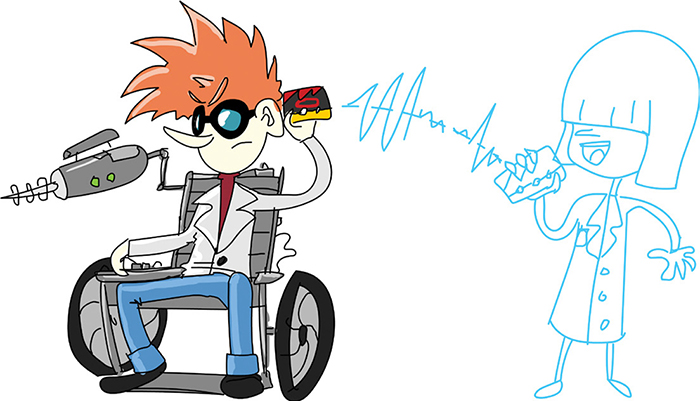
The Mad Scientist has made a friend. After hitting it off at a Mad Science Conference, the two decided they wanted to keep talking—through micro:bit, of course. The micro:bit has a built-in radio transmitter and receiver, together known as a transceiver, that can communicate with Bluetooth devices. We saw this in action in the roving robot project in Chapter 6.
This radio transceiver can also be used to talk to other micro:bits using a simple message-sending and receiving protocol specific to the micro:bit. In this chapter, we’ll look at micro:bit-to-micro:bit communication, so you’ll need either two of your own micro:bits or a friend with a micro:bit.
EXPERIMENT 12: FINDING THE RADIO RANGE

Difficulty: Easy
The Mad Scientist and a friend want to know how far apart they can be before their micro:bit communicators stop working.
What You’ll Need
You’ll need a pair of micro:bits, each equipped with a battery pack. You’ll also need a friend to talk to and a field or other open space where you can move away from each other.
Construction
- Go to https://github.com/simonmonk/mbms/ and click the link for Experiment 12: Radio Range. Copy the hex file onto both micro:bits. (Chapter 1 explains the full process of getting programs onto your micro:bit if you get stuck). If you want to run the MicroPython version of this experiment, that file is Experiment_12.py.
- Equip both micro:bits with battery power—you’re probably used to doing this by now.
Before you venture outdoors, test that both micro:bits are ready to go by pressing button A on one of the devices. An up arrow should appear on that micro:bit, and a check mark should appear on the other micro:bit. Repeat this test by pressing button A on the other micro:bit (Figure 10-1).

Figure 10-1: Testing the micro:bits
- Go to a place where you and your friend have plenty of room to move away from each other. Stand about a yard (or meter) apart, facing one another. You should have one micro:bit and your friend the other.
- Now either you or your friend presses button A on their micro:bit to transmit the signal. Then wave to let the other person know the signal was sent (in case they don’t receive it). When their device picks up the signal, they should wave back. Assuming the signal was successfully transmitted, take a few steps away from each other and repeat the test.
- At some point, the message won’t be received! The sender should press the button and wave one more time. If the message still isn’t received, you both know to move one step closer.
- Once you’ve determined the radio’s range, the sender uses a prearranged signal to tell the receiver to walk toward them, counting the number of steps that they take.
- Measure the length of a step taken by the receiver and multiply that by the number of steps they took. The resulting value is the line-of-sight range of the micro:bit’s radio. Tip: To get a reasonably accurate stride length, have the person walk five steps, use a long tape measure to measure the total distance traveled, and divide that distance by 5.
The Mad Scientist tested the range of two micro:bits and found it to be 192 strides. Five strides covered 12 feet (3.65 meters), meaning that each stride was 2.4 feet. The range was therefore 192 × 2.4 or approximately 460 feet (140 meters).
A range of over 1,100 feet (350 meters) has been reported by others carrying out this experiment. Note that the range will be considerably less if either your body or your friend’s is between the micro:bits.
Code
The code for the range test is fairly simple, whether you use Blocks or MicroPython.
Blocks Code
Here is the Blocks code for the project.

You can control the amount of power used by the radio. The on start block uses the radio set transmit power block to set the power to 7 (maximum)—more power means greater range. The set radio group block assigns a group for the radio to use. In this case, we use group 1, which means all the micro:bits set to radio group 1 will receive the transmissions. So, if you plan to carry out this experiment with multiple pairs of micro:bits at the same time, then each pair of experimenters should pick a different number between 0 and 255 and set the radio group to that number. This way, the different pairs won’t interfere with each other.
We use the on button A pressed block with the radio send block to transmit a simple message of test. This will flash the North arrow icon to show that the message has been sent.
We handle incoming messages with an on received block, specifying the name of the variable into which any incoming message should be put. In this case, whenever the micro:bit’s radio receives a message, it puts the message into the variable receivedString. If this message is test, then the check mark icon is displayed for a moment on the screen.
MicroPython Code
Here is the MicroPython version of the code. Note that the way messages are sent in MicroPython is slightly different from how they’re sent in the Blocks code, so the pair of micro:bits used in this experiment should both be programmed either in Blocks or in MicroPython.
import radio
radio.on()
radio.config(power=7, group=1)
while True:
if button_a.was_pressed():
radio.send("test")
display.show(Image.ARROW_N)
sleep(1000)
display.clear()
message = radio.receive()
if message == 'test':
display.show(Image.YES)
sleep(1000)
display.clear()
To set the radio’s power and radio group in MicroPython, we need to use the radio.config method. This method also allows you to control a number of other options. You can read about these at https://bbcmicrobitmicropython.readthedocs.io/en/latest/radio.html.
The Blocks version of the code is contained entirely in handlers. In MicroPython, we don’t have handlers, so we have to continually check for a button press or incoming message. We do this by having a set of if statements in a while True loop that is always running.
First, we check whether button A has been pressed since the previous check. If it has been, we send the message test and show the North arrow.
To check whether we’ve received a message, we repeatedly call message.receive. When the radio receives messages, it puts them in a queue. If there is no message waiting, then message.receive returns None. However, if there is one or more messages, then message.receive returns the oldest message and removes that message from the queue.
We only care whether the message is test, so we check this condition. If the message is test, we have the micro:bit display the YES icon for a second.
How It Works: Radio Signals
When outdoors, the range of the micro:bits’ radios is likely to be much greater than when you’re indoors, where walls between the micro:bits will impede the signal.
The system of sending messages between devices is called packet radio because small packets of data are being sent. In this project’s code, these are text commands.
PROJECT: WIRELESS DOORBELL

Difficulty: Medium
Distracted by experiments and insubordinate underlings, the Mad Scientist often misses packages when they’re delivered. To remedy this, they’ve decided to build a speaker in the lab that plays when the doorbell is rung.
We’ll build on the doorbell project from way back in Chapter 2. In this version of the project, we’ll use two micro:bits: one connected to a speaker, responsible for playing a tune, and a second one that acts as the doorbell button (Figure 10-2). When one of the buttons on the second micro:bit is pressed, it sends a radio message to the sound-making micro:bit, telling it to play a tune. Because the micro:bit radios have a pretty good range, your sound-playing micro:bit can be some distance from your door and, thus, closer to you.

Figure 10-2: The wireless doorbell project
What You’ll Need
For this project, you’ll need the following items:
2 × Micro:bit One that acts as a doorbell button and another that plays a tune
3 × Alligator clip cables To connect the micro:bit to the speaker
2 × USB power adapters or 3V battery packs with power switch To power the micro:bits
Speaker To play the doorbell tune, I recommend the Monk Makes Speaker for micro:bit.
Blu-Tak adhesive putty or self-adhesive pads To attach one of the micro:bits to the door frame
Construction
- Go to https://github.com/simonmonk/mbms/ and click the link for Wireless Doorbell. Copy the hex file onto both micro:bits. Chapter 1 explains the full process of getting programs onto your micro:bit if you need a refresher. If you want to run the MicroPython version of this experiment, that file is ch_10_Wireless_Doorbell.py.
- Connect a speaker to one of the micro:bits. You can use the speaker you used in the musical doorbell project from Chapter 2 (see the instructions for this project if you get stuck).
- Test the speaker by pressing button A on the doorbell micro:bit. The micro:bit attached to the speaker should immediately start playing the tune “The Entertainer.” When it’s finished, try pressing button B, and the “Funeral March” should play.
- Use the Blu-Tak adhesive putty or pads to attach the speakerless micro:bit to the outside of your door.
Code
Both versions of the code rely on sending a message over the radio of either db1 or db2, depending on which button is pressed. The receiving micro:bit then plays one of two tunes, depending on which message it receives.
As with Experiment 12, you cannot mix and match the MicroPython and Blocks versions of the code, so decide to use one or the other.
Blocks Code
Here is the Blocks code for the project.

You’ll notice that the code here is similar to that in Experiment 12. If Button A is pressed, then the string db1 (doorbell 1) is sent and a north arrow displayed to indicate that the message has been sent. The handler for when button B is pressed sends the message db2.
The receiving code checks whether the received message is db1 or db2 and plays the appropriate tune.
MicroPython Code
Here is MicroPython version of the code:
import radio, music
radio.on()
radio.config(power=7, group=1)
def send_message(message):
radio.send(message)
display.show(Image.ARROW_N)
sleep(1000)
display.clear()
while True:
if button_a.was_pressed():
send_message("db1")
if button_b.was_pressed():
send_message("db2")
message = radio.receive()
if message == 'db1':
music.play(music.ENTERTAINER)
elif message == 'db2':
music.play(music.FUNERAL)
In this version of the code, we’ve defined the function send_message, which sends a message using the radio and displays the north arrow for a second.
As with the code in Experiment 12, we use a while True loop to continuously check for button presses and received messages.
Things to Try
Try swapping in different tunes. Or you might try changing the code so that when db1 or db2 is received, the tune is played more than once. Then the Mad Scientist will be more likely to hear it!
How It Works: Sending and Receiving
You might be wondering why we use the same code for both the sender and the receiver. If we press button A on the micro:bit with a speaker attached, shouldn’t it receive its own message and play a tune? It turns out that while the micro:bit’s radio is busy transmitting, it cannot receive anything. Also, having just one program avoids confusion about which program goes on which micro:bit.
PROJECT: MICRO:BIT-CONTROLLED ROVER
Difficulty: Hard
No secret lab would be complete without a robot that can give instructions. Back in Chapter 6, we made a robot rover that could be controlled over Bluetooth using your phone. This project uses the same basic rover, but instead of controlling the rover with your phone and Bluetooth, you’ll use a second micro:bit and the micro:bit’s own way of communicating wirelessly. You’ll steer the rover by tilting the controlling micro:bit left, right, forward, or backward. Figure 10-3 shows the project, and you can see it in action at https://youtu.be/Qqr0fknoPQ4/.

Figure 10-3: A micro:bit-controlled rover
What You’ll Need
For this project, you’ll need the following items:
2 × Micro:bit
Kitronik Motor Driver Board for micro:bit (V2) To control the forward and backward motors
Low-cost robot chassis kit Includes two gear motors and a 4 × AA battery box
4 × AA batteries
AAA battery pack for micro:bit To power the micro:bit being used as the remote control
Screwdrivers Suitable for both the nuts and bolts on the chassis and the screw terminals on the motor controller board
Soldering equipment To attach wires to the gearmotors
Blu-Tack adhesive putty To attach the motor control board and micro:bit to the chassis

Construction
Use the rover you built in Chapter 6 or, if you haven’t built the rover yet, go back and follow construction steps 1 to 4 from that project. We’ll be using different software, however, so once the chassis is built, follow the instructions here. Don’t fit the batteries yet, or your rover might accidentally drive itself off your table!
- First, we’ll install the program for the rover part of the project. Go to https://github.com/simonmonk/mbms/ and click the link for Rover. Copy the hex file onto the micro:bit attached to the rover chassis. Head back to Chapter 1 if you need more detailed instructions on how to get programs onto your micro:bit.
- Now install the program for the micro:bit being used as the remote control. Go to the Github page, click the link for Rover Controller, click Download, and copy the hex file onto the micro:bit.
- Before you let your robot loose in the lab, it’s worth testing out your project without the wheels touching the ground. You may need to swap over some of the motor wires so the rover follows the commands you send it correctly. Insert the batteries and then flip the rover on its back so you can see what the wheels are doing, without any danger of its driving away.
Tip the controlling micro:bit to the left, and you should see the same left arrow appear on the displays of both micro:bits. At the same time, both wheels should turn in the same direction. As you look from above, the right wheel should be turning faster than the left. If one of the wheels is turning in the wrong direction, swap over the red and black wires at the motor controller screw terminal for that motor.
- Try driving the rover around. Remember that if the vehicle gets stuck, you can stop it by putting the controller micro:bit into a horizontal position.
Code
The software uses two programs, one for the controller and another for the rover micro:bit. You can only use Blocks code for this project
Controller Code
Here is the code for the remote controller micro:bit.

You’ll notice that in the on start block, we use a radio set group block. This block makes the micro:bit listen only to messages from other micro:bits in the same group—here group 1. This prevents your micro:bit from picking up stray messages from other scientists in the area who might be using the same radio group and behaving unpredictably as a result. If you want to add other micro:bit pairs, change the number in the radio set group block to a different value for each micro:bit pair. Then each rover will be paired to a single controller. You can pick any number between 0 and 255.
The rest of the program consists of on gesture blocks that handle the possible movement commands for the rover. For example, below the on start block, you have the on tilt left block, which transmits the string L and displays an East arrow when the micro:bit is tilted. Here’s the full list of commands that can be sent:
S Stop
L Left
R Right
B Backward
F Forward
Rover Code
Here is the receiving code for these commands.

Similar to the controller code, we have an on start block that sets the radio group to 1. Remember that if you decide to change the radio group code, you have to do it on both micro:bits!
The rest of the code is contained in an on radio received block. Inside the block is a series of if statements that test the incoming command letter and perform the action that letter signals. If the L command is received, for example, a left arrow is shown, and then motor 1 is set to go forward at 50 percent and motor 2 to go forward at 100 percent (full speed). This will make motor 2 (the right motor) go faster than the left motor, making the rover turn in an arc toward the left.
Things to Try
Try adding extra commands to the pair of programs. You’re getting a bit short on gestures to use, but you could add a D (for dance) command that tells the rover to do a little sequence of moves when the controller micro:bit is shaken.
You could also add a C (for circle) command that instructs the rover to spin on the spot by setting one motor forward at full speed and the other in reverse at full speed. This could be triggered by pressing button A or B.
How It Works: Motor Driver Blocks
You may have noticed a new category of blocks that appeared in your Blocks code when you opened the code for the rover: Motor Driver blocks. These blocks were created by Kitronik, the makers of the motor controller used in the project.
If you’re starting a new project and want to use these blocks, you first need to add them to your project. To do this, click Extensions at the bottom of the list of block categories. This will open a dialog that looks something like Figure 10-4. If the package isn’t listed after you search for it, refresh the browser page and try searching again.

Figure 10-4: Managing extensions in the Blocks editor
In the field at the top labeled Search or enter project URL . . . enter the following: https://github.com/KitronikLtd/pxt-kitronik-motor-driver/. To make sure you get the URL right, enter it into another browser tab first. When you’ve found the page, copy and paste the URL from your browser’s address bar to the field.
Once you’ve entered the URL, you should see kitronik-motor-driver, as shown in Figure 10-5. Click it, and you’ll find that your Blocks editor now has a new category containing the motor control blocks that you can drag into your code.

Figure 10-5: Managing extensions in the Blocks editor
Once the package has been added to your project, it will be stored in the project forever. You won’t need to install it again, unless you start a new project and want to use the package there. Because the package is stored in the project, you can easily share the project with someone else, with no need for them to install the package.
SUMMARY
In this chapter, you tested the range of the micro:bit’s built-in radio, built a better doorbell, and made a remote-controlled rover. With its good range, the radio lets micro:bits communicate with each other easily, and it lends itself to all sorts of communication projects.
This is the final chapter in this book. The appendix that follows will give you some information about the parts you need to build the projects in this book and where you might obtain them.
The micro:bit community is a vibrant and active one. You’ll find lots of interesting projects to make and experiments to carry out involving your micro:bit. Take a look at https://microbit.org/ideas/ if you want some inspiration for what you, as a Mad Scientist, might do next with your micro:bit.