15
Using GPS with Your Arduino
In this chapter, you will
- Learn how to connect a GPS shield
- Create a simple GPS coordinates display
- Show the actual position of GPS coordinates on a map
- Build an accurate clock
- Record the position of a moving object over time
You’ll learn how to use an inexpensive GPS shield to determine location, create an accurate clock, and make a logging device that records the position of your gadget over time onto a microSD card, which can then be plotted over a map to display movement history.
What Is GPS?
The Global Positioning System (GPS) is a satellite-based navigation system that sends data from satellites orbiting Earth to GPS receivers on the ground that can use that data to determine the current position and time anywhere on Earth. You are probably already familiar with GPS navigation devices used in cars or on your smartphone.
Although we can’t create detailed map navigation systems with our Arduinos, you can use a GPS module to determine your position, time, and approximate speed (if you’re in motion). When shopping around for a GPS module, you will generally find two types available. The first is an independent, inexpensive GPS receiver on a module with an external aerial, as shown in Figure 15-1.

Figure 15-1: A GPS receiver module
The second type you will come across is a GPS shield for Arduino, as shown in Figure 15-2. These shields are convenient, since all the wiring is done for you; they also include a microSD card socket that is ideal for logging data, as demonstrated later in this chapter.
Ensure your GPS shield allows connection of the GPS receiver’s TX and RX lines to Arduino digital pins D2 and D3, or has jumpers to allow manually setting these (like the shield in Figure 15-2). Check with the supplier for more details. You can use either type of device in this chapter. However, I highly recommend the shield, especially as you can effortlessly connect an LCD shield on top of the GPS shield as a display.

Figure 15-2: A GPS shield for Arduino
Testing the GPS Shield
After you buy a GPS kit, it’s a good idea to make sure that it’s working and that you can receive GPS signals. GPS receivers require a line of sight to the sky, but their signals can pass through windows. So, while it’s usually best to perform this test outdoors, your GPS receiver will probably work just fine through an unobstructed window or skylight. To test reception, you’ll set up the shield or module and run a basic sketch that displays the raw received data.
If you are using a GPS shield, ensure that the GPS TX pin is jumpered to Arduino digital pin D2 and the RX pin is jumpered to Arduino digital pin D3. If you are using a GPS module, as shown in Figure 15-1, connect the Vcc and GND to Arduino 5 V and GND, respectively; then connect TX to Arduino digital pin D2 and RX to Arduino digital pin D3.
To perform the test, enter and upload the sketch in Listing 15-1.
// Listing 15-1
#include <SoftwareSerial.h>

// GPS TX to D2, RX to D3
SoftwareSerial Serial2(2, 3);

byte gpsData;

void setup()
{
// Open the Arduino Serial Monitor
  Serial.begin(9600);
// Open the GPS
1   Serial2.begin(9600);
}

void loop()
{
2   while (Serial2.available() > 0)
  {
    // get the byte data from the GPS
    gpsData = Serial2.read();
3     Serial.write(gpsData);
  }
}
Listing 15-1: Basic GPS test sketch
This sketch listens to the software serial port at 2, and when a byte of data is received from the GPS module or shield, it is sent to the Serial Monitor at 3. (Notice that we start the software serial port at 9,600 bps at 1 to match the data speed of the GPS receiver.)
Once you’ve uploaded the sketch, you may need to wait around 30 seconds; this is to allow the GPS receiver time to start receiving signals from one or more GPS satellites. The GPS shield or module will have an onboard LED, which will start flashing once the receiver has started finding GPS signals. After the LED starts blinking, open the Serial Monitor window in the IDE and set the data speed to 9,600 baud. You should see a constant stream of data similar to the output shown in Figure 15-3.

Figure 15-3: Raw data from GPS satellites
The data is sent from the GPS receiver to the Arduino one character at a time, and then it is sent to the Serial Monitor. But this raw data (called GPS sentences) is not very useful as it is, so we need to use a new library that extracts information from the raw data and converts it to a usable form. To do this, download and install the TinyGPS library from http://www.arduiniana.org/libraries/tinygps/ using the method described in Chapter 7.
Project #43: Creating a Simple GPS Receiver
We’ll start by creating a simple GPS receiver. Because you’ll usually use your GPS outdoors—and to make things a little easier—we’ll add an LCD module to display the data, similar to the one shown in Figure 15-4.
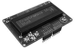
Figure 15-4: The Freetronics LCD & Keypad Shield
The result will be a very basic portable GPS that can be powered by a 9 V battery and connector, which will display the coordinates of your current position on the LCD.
The Hardware
The required hardware is minimal:
- Arduino and USB cable
- LCD module or Freetronics LCD & Keypad Shield
- One 9 V battery–to–DC socket cable
- GPS module and screw shield for Arduino or GPS shield for Arduino
The Sketch
Enter and upload the following sketch:
// Project 43 - Creating a Simple GPS Receiver
1 #include <LiquidCrystal.h>
LiquidCrystal lcd(8, 9, 4, 5, 6, 7);

#include <TinyGPS.h>
#include <SoftwareSerial.h>

// GPS TX to D2, RX to D3

SoftwareSerial Serial2(2, 3);

TinyGPS gps;
void getgps(TinyGPS &gps);

byte gpsData;

2 void getgps(TinyGPS &gps)
// The getgps function will display the required data on the LCD
{
  float latitude, longitude;
  // decode and display position data
3   gps.f_get_position(&latitude, &longitude);
  lcd.setCursor(0, 0);
  lcd.print("Lat:");
  lcd.print(latitude, 5);
  lcd.print(" ");
  lcd.setCursor(0, 1);
  lcd.print("Long:");
  lcd.print(longitude, 5);
  lcd.print(" ");
  delay(3000); // wait for 3 seconds
  lcd.clear();
}

void setup()
{
  Serial2.begin(9600);
}

void loop()
{
  while (Serial2.available() > 0)
  {
    // get the byte data from the GPS
    gpsData = Serial2.read();
    if (gps.encode(gpsData))
    {
4       getgps(gps);
    }
  }
}
From 1 to 2, the sketch introduces the required libraries for the LCD and GPS. In void loop(), we send the characters received from the GPS receiver to the function getgps() at 4. The data is obtained by using gps.f_get_position() at 3 to insert the position values in the byte variables &latitude and &longitude, which we display on the LCD.
Running the Sketch
After the sketch has been uploaded and the GPS starts receiving data, your current position in decimal latitude and longitude should be displayed on your LCD, as shown in Figure 15-5.

Figure 15-5: Latitude and longitude display from Project 43
But where on Earth is this? We can determine exactly where it is by using Google Maps (http://maps.google.com/). On the website, enter the latitude and longitude, separated by a comma and a space, into the search field, and Google Maps will return the location. For example, using the coordinates returned in Figure 15-5 produces a map like the one shown in Figure 15-6.
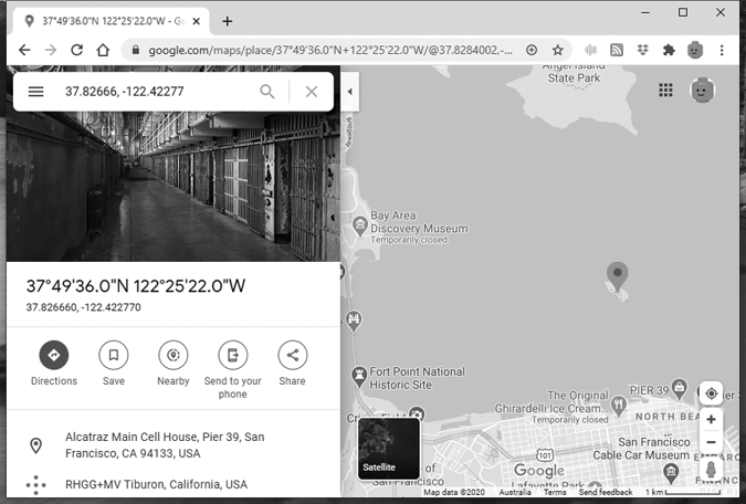
Figure 15-6: The GPS coordinates displayed in Figure 15-5 place us on Alcatraz Island.
Project #44: Creating an Accurate GPS-Based Clock
There is more to using a GPS than finding a location; the system also transmits time data that can be used to make a very accurate clock.
The Hardware
For this project, we’ll use the same hardware as in Project 43.
The Sketch
Enter and upload the following sketch to build a GPS clock:
// Project 44 - Creating an Accurate GPS-Based Clock
#include <LiquidCrystal.h>
#include <TinyGPS.h>
#include <SoftwareSerial.h>
LiquidCrystal lcd(8, 9, 4, 5, 6, 7);

// GPS RX to D3, GPS TX to D2
SoftwareSerial Serial2(2, 3);

TinyGPS gps;
void getgps(TinyGPS &gps);

byte gpsData;

void getgps(TinyGPS &gps)
{
  byte month, day, hour, minute, second, hundredths;
1   gps.crack_datetime(&year,&month,&day,&hour,&minute,&second,&hundredths);
2   hour=hour+10; // change the offset so it is correct for your time zone
  if (hour>23)
  {
    hour=hour-24;
  }
  lcd.setCursor(0,0); // print the date and time
3   lcd.print("Current time: ");
  lcd.setCursor(4,1);
  if (hour<10)
  {
    lcd.print("0");
  }
  lcd.print(hour, DEC);
  lcd.print(":");
  if (minute<10)
  {
    lcd.print("0");
  }
  lcd.print(minute, DEC);
  lcd.print(":");
  if (second<10)
  {
    lcd.print("0");
  }
  lcd.print(second, DEC);
}

void setup()
{
  Serial2.begin(9600);
}

void loop()
{
  while (Serial2.available() > 0)
  {
    // get the byte data from the GPS
    gpsData = Serial2.read();
    if (gps.encode(gpsData))
    {
      getgps(gps);
    }
  }
}
This example works in a similar way to the sketch in Project 43, except that instead of extracting the position data, it extracts the time (always at Greenwich Mean Time, more commonly known as UTC) at 1. At 2, you can either add or subtract a number of hours to bring the clock into line with your current time zone. The time should then be formatted clearly and displayed on the LCD at 3. Figure 15-7 shows an example of the clock.

Figure 15-7: Project 44 at work
Project #45: Recording the Position of a Moving Object over Time
Now that we know how to receive GPS coordinates and convert them into normal variables, we can use this information with a microSD or SD card, introduced in Chapter 7, to build a GPS logger. Our logger will record our position over time by logging the GPS data over time. The addition of the memory card will allow you to record the movement of a car, truck, boat, or any other moving object that allows GPS signal reception; later, you can review the information on a computer.
The Hardware
If you have a GPS shield for Arduino, as recommended earlier in this chapter, the required hardware is the same as that used for the previous examples, except that you can remove the LCD shield. If you’re using a GPS receiver module, you will need the screw shield to allow connection of the GPS and the SD card module. No matter which method you use, you will need external power for this project. In our example, we’ll record the time, position information, and estimated speed of travel.
The Sketch
After assembling your hardware, enter and upload the following sketch:
// Project 45 - Recording the Position of a Moving Object over Time

#include <TinyGPS.h>
#include <SoftwareSerial.h>
#include <SD.h>

// GPS TX to D2, RX to D3

SoftwareSerial Serial2(2, 3);

TinyGPS gps;
void getgps(TinyGPS &gps);

byte gpsData;

void getgps(TinyGPS &gps)
{
  float latitude, longitude;
  int year;
  byte month, day, hour, minute, second, hundredths;

  // create/open the file for writing
  File dataFile = SD.open("DATA.TXT", FILE_WRITE);
  // if the file is ready, write to it:
1   if (dataFile)
  {
2     gps.f_get_position(&latitude, &longitude);
    dataFile.print("Lat: ");
    dataFile.print(latitude, 5);
    dataFile.print(" ");
    dataFile.print("Long: ");
    dataFile.print(longitude, 5);
    dataFile.print(" ");
    // decode and display time data
    gps.crack_datetime(&year, &month, &day, &hour, &minute, &second,
                       &hundredths);
    // correct for your time zone as in Project 44
    hour = hour + 10;
    if (hour > 23)
    {
      hour = hour - 24;
    }
    if (hour < 10)
    {
      dataFile.print("0");
    }
    dataFile.print(hour, DEC);
    dataFile.print(":");
    if (minute < 10)
    {
      dataFile.print("0");
    }
    dataFile.print(minute, DEC);
    dataFile.print(":");
    if (second < 10)
    {
      dataFile.print("0");
    }
    dataFile.print(second, DEC);
    dataFile.print(" ");
    dataFile.print(gps.f_speed_kmph());
3     dataFile.println("km/h");
    dataFile.close();
4     delay(15000); // record a measurement around every 15 seconds
  }
  // if the file isn't ready, show an error:
  else
  {
    Serial.println("error opening DATA.TXT");
  }
}

void setup()
{
  Serial.begin(9600);
  Serial2.begin(9600);
  Serial.println("Initializing SD card...");
  pinMode(10, OUTPUT);
  // check that the memory card exists and is usable
  if (!SD.begin(10))
  {
    Serial.println("Card failed, or not present");
    // stop sketch
    return;
  }
  Serial.println("memory card is ready");
}

void loop()
{
  while (Serial2.available() > 0)
  {
    // get the byte data from the GPS
    gpsData = Serial2.read();
    if (gps.encode(gpsData))
    {
5       getgps(gps);
    }
  }
}
This sketch uses the same code used in Projects 43 and 44 in void loop() to receive data from the GPS receiver and pass it on to other functions. At 5, the data from the GPS receiver is passed into the TinyGPS library to decode it into useful variables. At 1, the memory card is checked to determine whether data can be written to it, and from 2 to 3, the relevant GPS data is written to the text file on the microSD card. Because the file is closed after every write, you can remove the power source from the Arduino without warning the sketch, and you should do so before inserting or removing the microSD card. Finally, you can set the interval between data recordings at 4 by changing the value in the delay() function.
Running the Sketch
After operating your GPS logger, the resulting text file should look similar to Figure 15-8.
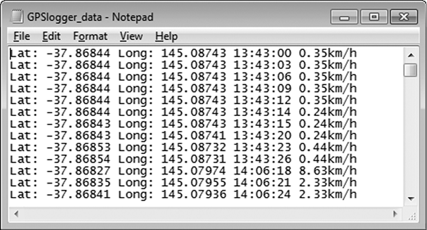
Figure 15-8: Results from Project 45
Once you have this data, you can enter it into Google Maps manually and review the path taken by the GPS logger, point by point. But a more interesting method is to display the entire route taken on one map. To do this, open the text file as a spreadsheet, separate the position data, and add a header row, as shown in Figure 15-9. Then save it as a .csv file.
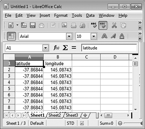
Figure 15-9: Captured position data
Now visit the GPS Visualizer website (http://www.gpsvisualizer.com/). In the Get Started Now box, click Choose File and select your data file. Choose Google Maps as the output format and then click Map It. The movement of your GPS logger should be shown on a map similar to the one in Figure 15-10, which you can then adjust and explore.
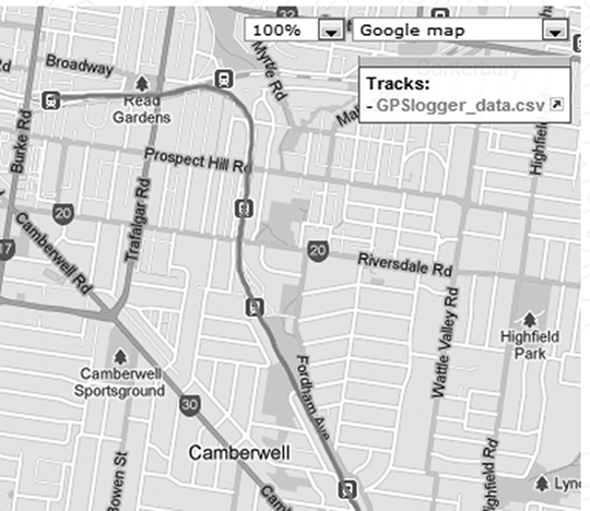
Figure 15-10: Mapped GPS logger data
Looking Ahead
As you can see, something that you might have thought too complex, such as working with GPS receivers, can be made simple with your Arduino. Continuing with that theme, in the next chapter you’ll learn how to create your own wireless data links and direct things via remote control.