17
Infrared Remote Control
In this chapter you will
- Create and test a simple infrared receiver
- Remotely control Arduino digital output pins
- Add a remote control system to the robot vehicle we created in Chapter 14
As you’ll see, with the addition of an inexpensive receiver module, your Arduino can receive the signals from an infrared remote and act upon them.
What Is Infrared?
Many people use infrared remote controls in a variety of daily actions, and most don’t know how they work. Infrared (IR) signals are beams of light at a wavelength that cannot be seen by the naked eye. So when you look at the little LED poking out of a remote control and press a button, you won’t see the LED light up.
That’s because IR remote controls contain one or more special infrared light–generating LEDs that transmit the IR signals. When you press a button on the remote, the LED turns on and off repeatedly in a pattern that is unique for each button pressed. This signal is received by a special IR receiver on the device being controlled and converted to pulses of electrical current that are read as data by the receiver’s electronics. If you are curious about these patterns, you can view them by looking at the IR LED on a remote through the viewfinder of a phone camera or digital camera.
Setting Up for Infrared
Before moving forward, we need to install the Arduino IRremote library, so visit https://github.com/z3t0/Arduino-IRremote/archive/master.zip to download the required files and install them using the method described in Chapter 7.
The IR Receiver
The next step is to set up the IR receiver and test that it is working. You can choose either an independent IR receiver (shown in Figure 17-1) or a prewired module (shown in Figure 17-2), whichever is easier for you.
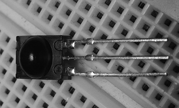
Figure 17-1: An IR receiver
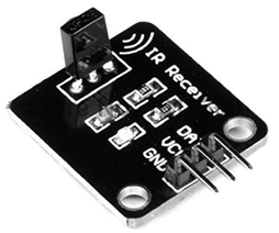
Figure 17-2: A prewired IR receiver module
The independent IR receiver shown in Figure 17-1 is a Vishay TSOP4138. The bottom leg of the receiver (as shown in the figure) connects to an Arduino digital pin, the center leg to GND, and the top leg to 5 V.
Figure 17-2 shows a prewired IR module. Prewired receiver modules are available from PMD Way and other retailers. The benefit of using these modules is that they include connection wires and are labeled for easy reference.
Regardless of your choice of module, in all of the following examples, you’ll connect D (the data line) to Arduino digital pin 2, VCC to 5 V, and GND to GND.
The Remote Control
Finally, you will need a remote control. I’ve used a surplus Sony TV remote like the one shown in Figure 17-3. If you don’t have access to a Sony remote, any inexpensive universal remote control can be used after you reset it to Sony codes. See the instructions included with your remote control to do this.
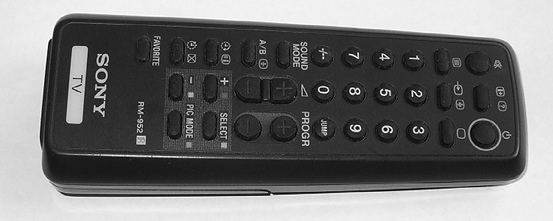
Figure 17-3: A typical Sony remote control
A Test Sketch
Now let’s make sure that everything works. After connecting your IR receiver to the Arduino, enter and upload the sketch in Listing 17-1.
// Listing 17-1

1 #include <IRremote.h>       // use the library

2 IRrecv irrecv(receiverpin); // create instance of irrecv
3 decode_results results;
int receiverpin = 2;        // pin 1 of IR receiver to Arduino digital pin 2

void setup()
{
  Serial.begin(9600);
  irrecv.enableIRIn();      // start the IR receiver
}

void loop()
{
4   if (irrecv.decode(&results))        // have we received an IR signal?
  {
5     Serial.print(results.value, HEX); // display IR code in the Serial Monitor
    Serial.print(" ");
    irrecv.resume();                  // receive the next value
  }
}
Listing 17-1: IR receiver test
This sketch is relatively simple, because most of the work is done in the background by the IR library. At 4, we check whether a signal has been received from the remote control. If so, it is displayed in the Serial Monitor in hexadecimal at 5. The lines at 1, 2, and 3 activate the IR library and create an instance of the infrared library function to refer to in the rest of the sketch.
Testing the Setup
Once you’ve uploaded the sketch, open the Serial Monitor, aim the remote at the receiver, and start pressing buttons. You should see codes for the buttons displayed in the Serial Monitor after each button press. For example, Figure 17-4 shows the results of pressing 1, 2, and 3, once each.
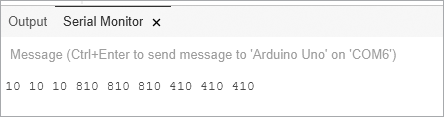
Figure 17-4: Results of pressing buttons after running the code in Listing 17-1
Table 17-1 lists the codes from a basic Sony remote control that we’ll use in upcoming sketches. However, when running Listing 17-1, notice that each code number repeats three times. This is an idiosyncrasy of Sony IR systems, which send the code three times for each button press. You can ignore these repeats with some clever coding, but for now, let’s skip to remote controlling with the next project.
Table 17-1: Example Sony IR codes
| Button | Code | Button | Code |
| Power | A90 | 7 | 610 |
| Mute | 290 | 8 | E10 |
| 1 | 10 | 9 | 110 |
| 2 | 810 | 0 | 910 |
| 3 | 410 | Volume up | 490 |
| 4 | C10 | Volume down | C90 |
| 5 | 210 | Channel up | 90 |
| 6 | A10 | Channel down | 890 |
Project #50: Creating an IR Remote Control Arduino
This project will demonstrate how to control digital output pins using an IR remote control. You’ll control digital pins 3 through 7 with the matching numerical buttons 3 through 7 on a Sony remote control. When you press a button on the remote control, the matching digital output pin will change state to HIGH for 1 second and then return to LOW. You’ll be able to use this project as a base or guide to add remote control capabilities to your other projects.
The Hardware
The following hardware is required for this project:
- Arduino and USB cable
- Five LEDs
- Five 560 Ω resistors
- Infrared receiver or module
- Solderless breadboard
- Various jumper wires
The Schematic
The circuit consists of the infrared receiver with the output connected to digital pin 2 and five LEDs with current-limiting resistors connected to digital pins 3 to 7 inclusive, as shown in Figure 17-5.
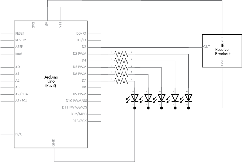
Figure 17-5: Schematic for Project 50
The Sketch
Enter and upload the following sketch:
// Project 50 – Creating an IR Remote Control Arduino

#include <IRremote.h>
IRrecv irrecv(receiverpin); // create instance of irrecv
decode_results results;
int receiverpin = 2;        // pin 1 of IR receiver to Arduino digital pin 2
void setup()
{
  irrecv.enableIRIn();      // start the receiver
  for (int z = 3 ; z < 8 ; z++) // set up digital pins
  {
    pinMode(z, OUTPUT);
  }
}

1 void translateIR()
// takes action based on IR code received
// uses Sony IR codes
{
  switch(results.value)
  {
2     case 0x410:  pinOn(3); break; // 3
    case 0xC10:  pinOn(4); break; // 4
    case 0x210:  pinOn(5); break; // 5
    case 0xA10:  pinOn(6); break; // 6
    case 0x610:  pinOn(7); break; // 7
  }
}

3 void pinOn(int pin) // turns on digital pin "pin" for 1 second
{
  digitalWrite(pin, HIGH);
  delay(1000);
  digitalWrite(pin, LOW);
}

void loop()
{
4   if (irrecv.decode(&results))    // have we received an IR signal?
  {
    translateIR();
5     for (int z = 0 ; z < 2 ; z++) // ignore the 2nd and 3rd repeated codes
    {
      irrecv.resume();            // receive the next value
    }
  }
}
This sketch has three major parts. First, it waits for a signal from the remote at 4. When a signal is received, the signal is tested in the function translateIR() at 1 to determine which button was pressed and what action to take.
Notice at 2 that we compare the hexadecimal codes returned by the IR library. These are the codes returned by the test conducted in Listing 17-1. When the codes for buttons 3 through 7 are received, the function pinOn() at 3 is called, which turns on the matching digital pin for 1 second.
As mentioned, Sony remotes send the code three times for each button press, so we use a small loop at 5 to ignore the second and third codes. Finally, note the addition of 0x in front of the hexadecimal numbers used in the case statements at 2.
Modifying the Sketch
You can expand the options or controls available for controlling your receiving device by testing more buttons. To do so, use Listing 17-1 to determine which button creates which code and then add each new code to the switch case statement.
Project #51: Creating an IR Remote Control Robot Vehicle
To show you how to integrate an IR remote control into an existing project, we’ll add IR to the robot described in Project 39 in Chapter 14. In this project, instead of presetting the robot’s direction and distances, the sketch will show you how to control these actions with a simple Sony TV remote.
The Hardware
The required hardware is the same as that required for the robot you built for Project 39, with the addition of the IR receiver module described earlier in this chapter. In the following sketch, the robot will respond to the buttons that you press on the remote control as follows: press 2 for forward, 8 for backward, 4 for rotate left, and 6 for rotate right.
The Sketch
After reassembling your vehicle and adding the IR receiver, enter and upload the following sketch:
// Project 51 - Creating an IR Remote Control Robot Vehicle
int receiverpin = 2; // pin 1 of IR receiver to Arduino digital pin 11
#include <IRremote.h>
IRrecv irrecv(receiverpin); // create instance of irrecv
decode_results results;
#include <AFMotor.h>
AF_DCMotor motor1(1); // set up instances of each motor
AF_DCMotor motor2(2);
AF_DCMotor motor3(3);
AF_DCMotor motor4(4);

void goForward(int speed, int duration)
{
  motor1.setSpeed(speed);
  motor2.setSpeed(speed);
  motor3.setSpeed(speed);
  motor4.setSpeed(speed);
  motor1.run(FORWARD);
  motor2.run(FORWARD);
  motor3.run(FORWARD);
  motor4.run(FORWARD);
  delay(duration);
  motor1.run(RELEASE);
  motor2.run(RELEASE);
  motor3.run(RELEASE);
  motor4.run(RELEASE);
}

void goBackward(int speed, int duration)
{
  motor1.setSpeed(speed);
  motor2.setSpeed(speed);
  motor3.setSpeed(speed);
  motor4.setSpeed(speed);
  motor1.run(BACKWARD);
  motor2.run(BACKWARD);
  motor3.run(BACKWARD);
  motor4.run(BACKWARD);
  delay(duration);
  motor1.run(RELEASE);
  motor2.run(RELEASE);
  motor3.run(RELEASE);
  motor4.run(RELEASE);
}

void rotateLeft(int speed, int duration)
{
  motor1.setSpeed(speed);
  motor2.setSpeed(speed);
  motor3.setSpeed(speed);
  motor4.setSpeed(speed);
  motor1.run(FORWARD);
  motor2.run(BACKWARD);
  motor3.run(BACKWARD);
  motor4.run(FORWARD);
  delay(duration);
  motor1.run(RELEASE);
  motor2.run(RELEASE);
  motor3.run(RELEASE);
  motor4.run(RELEASE);
}

void rotateRight(int speed, int duration)
{
  motor1.setSpeed(speed);
  motor2.setSpeed(speed);
  motor3.setSpeed(speed);
  motor4.setSpeed(speed);
  motor1.run(BACKWARD);
  motor2.run(FORWARD);
  motor3.run(FORWARD);
  motor4.run(BACKWARD);
  delay(duration);
  motor1.run(RELEASE);
  motor2.run(RELEASE);
  motor3.run(RELEASE);
  motor4.run(RELEASE);
}

// translateIR takes action based on IR code received, uses Sony IR codes
void translateIR()
{
  switch (results.value)
  {
    case 0x810:
      goForward(255, 250);
      break; // 2
    case 0xC10:
      rotateLeft(255, 250);
      break; // 4
    case 0xA10:
      rotateRight(255, 250);
      break; // 6
    case 0xE10:
      goBackward(255, 250);
      break; // 8
  }
}

void setup()
{
  delay(5000);
  irrecv.enableIRIn();         // start IR receiver
}

void loop()
{
  if (irrecv.decode(&results)) // have we received an IR signal?
  {
    translateIR();
    for (int z = 0 ; z < 2 ; z++) // ignore the repeated codes
    {
      irrecv.resume();            // receive the next value
    }
  }
}
This sketch should look somewhat familiar to you. Basically, instead of lighting up LEDs on digital pins, it calls the motor control functions that were used in the robot vehicle from Chapter 14.
Looking Ahead
Having worked through the projects in this chapter, you should understand how to send commands to your Arduino via an infrared remote control device. Using these skills and your knowledge from previous chapters, you now can replace physical forms of input such as buttons with a remote control.
But the fun doesn’t stop here. In the next chapter, we’ll use an Arduino to harness something that, to the untrained eye, is fascinating and futuristic: radio frequency identification systems.