
19
Data Buses
In this chapter you will
- Learn about the I2C bus
- See how to use an EEPROM and a port expander on the I2C bus
- Learn about the SPI bus
- Find out how to use a digital rheostat on the SPI bus
An Arduino communicates with other devices via a data bus, a system of connections that allows two or more devices to exchange data in an orderly manner. A data bus can provide a connection between the Arduino and various sensors, I/O expansion devices, and other components.
The two major buses of most importance to the Arduino are the Serial Peripheral Interface (SPI) bus and the Inter-Integrated Circuit (I2C) bus. Many useful sensors and external devices communicate using these buses.
The I2C Bus
The I2C bus, also known as the Two-Wire Interface (TWI) bus, is a simple and easy-to-use data bus. Data is transferred between devices and the Arduino through two wires, known as SDA and SCL (the data line and clock line, respectively). In the case of the Arduino Uno, the SDA pin is A4 and the SCL pin is A5, as shown in Figure 19-1.
Some newer R3 boards also have dedicated I2C pins at the upper-left corner for convenient access, as shown in Figure 19-2. If you use these two pins, you cannot use the A4 and A5 pins for other purposes.

Figure 19-1: The I 2C bus connectors on the Arduino Uno

Figure 19-2: Additional dedicated I 2C pins
As the six pins used for reprogramming the USB interface microcontroller take up the space normally used for pin labeling, you can see the labels on the rear of the Arduino, as shown in Figure 19-3.

Figure 19-3: Labels for additional dedicated I 2C pins
On the I2C bus, the Arduino is the main device, and each IC out on the bus is a secondary. Each secondary has its own address, a hexadecimal number that allows the Arduino to address and communicate with each device. Each device usually has a range of 7-bit I2C bus addresses to choose from, which is detailed in the manufacturer’s data sheet. The particular addresses available are determined by wiring the IC pins a certain way.
To use the I2C bus, you’ll need to use the Wire library (included with the Arduino IDE):
#include <Wire.h> Next, in void setup(), activate the bus with this:
Wire.begin();Data is transmitted along the bus 1 byte at a time. To send a byte of data from the Arduino to a device on the bus, three functions are required:
- The first function initiates communication with the following line of code (where address is the secondary device’s bus address in hexadecimal—for example
0x50):Wire.beginTransmission(address); - The second function sends 1 byte of data from the Arduino to the device addressed by the previous function (where data is a variable containing 1 byte of data; you can send more than 1 byte, but you’ll need to use one
Wire.write()call for each byte):Wire.write(data); - Finally, once you have finished sending data to a particular device, use this to end the transmission:
Wire.endTransmission();
To request that data from an I2C device be sent to the Arduino, start with Wire.beginTransmission(address), followed by the this code (where x is the number of bytes of data to request):
Wire.requestFrom(address,x);Next, use the following function to store each incoming byte into a variable:
incoming = Wire.read(); // incoming is the variable receiving the byte of dataThen finalize the transaction with Wire.endTransmission(). We’ll put these functions to use in the next project.
Project #54: Using an External EEPROM
In Chapter 18, we used the Arduino’s internal EEPROM to prevent the erasure of variable data caused by a board reset or power failure. The Arduino’s internal EEPROM stores only 1,024 bytes of data. To store more data, you can use external EEPROMs, as you’ll see in this project.
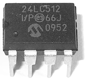
Figure 19-4: Microchip Technology’s 24LC512 EEPROM
For our external EEPROM, we’ll use the Microchip Technology 24LC512 EEPROM, which can store 64KB (65,536 bytes) of data (Figure 19-4). It’s available from retailers such as Digi-Key (part number 24LC512-I/P-ND) and PMD Way (part number 24LC512A).
The Hardware
Here’s what you’ll need to create this project:
- Arduino and USB cable
- One Microchip Technology 24LC512 EEPROM
- One breadboard
- Two 4.7 kΩ resistors
- One 100 nF ceramic capacitor
- Various connecting wires
The Schematic
For the circuit, connect one 4.7 kΩ resistor between 5 V and SCL and the other between 5 V and SDA, as shown in Figure 19-5.

Figure 19-5: Schematic for Project 54
The bus address for the 24LC512 EEPROM IC is partially determined by the way it is wired into the circuit. The last 3 bits of the bus address are determined by the status of pins A2, A1, and A0. When these pins are connected to GND, their values are 0; when they are connected to 5 V, their values are 1.
The first 4 bits are preset as 1010. Therefore, in our circuit, since A0, A1, and A2 are connected directly to GND, the bus address is represented as 1010000 in binary, which is 0x50 in hexadecimal. This means that we can use 0x50 as the bus address in the sketch.
The Sketch
Although our external EEPROM can store up to 64KB of data, our sketch is intended to demonstrate just a bit of its use, so we’ll store and retrieve bytes only in the EEPROM’s first 20 memory positions.
Enter and upload the following sketch:
// Project 54 - Using an External EEPROM
1 #include <Wire.h>
#define chip1 0x50

byte d=0;

void setup()
{
2   Serial.begin(9600);
  Wire.begin();
}

void writeData(int device, unsigned int address, byte data)
// writes a byte of data 'data' to the EEPROM at I2C address 'device'
// in memory location 'address'
{
3   Wire.beginTransmission(device);
  Wire.write((byte)(address >> 8));   // left part of pointer address
  Wire.write((byte)(address & 0xFF)); // and the right
  Wire.write(data);
  Wire.endTransmission();
  delay(10);
}

4 byte readData(int device, unsigned int address)
// reads a byte of data from memory location 'address'
// in chip at I2C address 'device'
{
  byte result;  // returned value
  Wire.beginTransmission(device);
  Wire.write((byte)(address >> 8));   // left part of pointer address
  Wire.write((byte)(address & 0xFF)); // and the right
  Wire.endTransmission();
5   Wire.requestFrom(device,1);
  result = Wire.read();
  return result; // and return it as a result of the function readData
}

void loop()
{
  Serial.println("Writing data...");
  for (int a=0; a<20; a++)
  {
    writeData(chip1,a,a);
  }
  Serial.println("Reading data...");
  for (int a=0; a<20; a++)
  {
    Serial.print("EEPROM position ");
    Serial.print(a);
    Serial.print(" holds ");
    d=readData(chip1,a);
    Serial.println(d, DEC);
  }
}
Let’s walk through the sketch. At 1, we activate the library and define the I2C bus address for the EEPROM as chip1. At 2, we start the Serial Monitor and then the I2C bus. The two custom functions writeData() and readData() are included to save you time and give you some reusable code for future work with this EEPROM IC. We’ll use them to write and read data, respectively, from the EEPROM.
The function writeData() at 3 initiates transmission with the EEPROM, sends the address of where to store the byte of data in the EEPROM using the next two Wire.write() function calls, sends a byte of data to be written, and then ends transmission.
The function readData() at 4 operates the I2C bus in the same manner as writeData(). First, however, it sets the address to read from, and then instead of sending a byte of data to the EEPROM, it uses Wire.requestFrom() to read the data at 5. Finally, the byte of data sent from the EEPROM is received into the variable result and becomes the return value for the function.
Running the Sketch
In void loop(), the sketch loops 20 times and writes a value to the EEPROM each time. Then it loops again, retrieving the values and displaying them in the Serial Monitor, as shown in Figure 19-6.

Figure 19-6: Results of Project 54
Project #55: Using a Port Expander IC
A port expander is another useful IC that is controlled via I2C. It’s designed to offer more digital output pins. In this project, we’ll use the Microchip Technology MCP23017 16-bit port expander IC (Figure 19-7), which has 16 digital outputs to add to your Arduino. It is available from retailers such as Digi-Key (part number MCP23017-E/SP-ND) and PMD Way (part number MCP23017A).

Figure 19-7: Microchip Technology’s MCP23017 port expander IC
In this project, we’ll connect the MCP23017 to an Arduino and demonstrate how to control the 16 port expander outputs with the Arduino. Each of the port expander’s outputs can be treated like a regular Arduino digital output.
The Hardware
Here’s what you’ll need to create this project:
- Arduino and USB cable
- One breadboard
- Various connecting wires
- One Microchip Technology MCP20317 port expander IC
- Two 4.7 kΩ resistors
- (Optional) An equal number of 560 Ω resistors and LEDs
The Schematic
Figure 19-8 shows the basic schematic for an MCP23017. As with the EEPROM from Project 54, we can set the I2C bus address by using a specific wiring order. With the MCP23017, we connected pins 15 through 17 to GND to set the address to 0x20.
When you’re working with the MCP23017, it helps to have the pinout diagram from the IC’s data sheet, as shown in Figure 19-9. Note that the 16 outputs are divided into two banks: GPA7 through GPA0 on the right and GPB0 through GPB7 on the left. We’ll connect LEDs via 560 Ω resistors from some or all of the outputs to demonstrate when the outputs are being activated.

Figure 19-8: Schematic for Project 55

Figure 19-9: Pinout diagram for MCP23017
The Sketch
Enter and upload the following sketch:
// Project 55 - Using a Port Expander IC

#include "Wire.h"
#define mcp23017 0x20

void setup()
{
1   Wire.begin();     // activate I2C bus
  // set up MCP23017
  // set I/O pins to outputs
  Wire.beginTransmission(mcp23017);
  Wire.write(0x00); // IODIRA register
  Wire.write(0x00); // set all of bank A to outputs
  Wire.write(0x00); // set all of bank B to outputs
2   Wire.endTransmission();
}

void loop()
{
    Wire.beginTransmission(mcp23017);
    Wire.write(0x12);
3     Wire.write(255);    // bank A
4     Wire.write(255);    // bank B
    Wire.endTransmission();
    delay(1000);

    Wire.beginTransmission(mcp23017);
    Wire.write(0x12);
    Wire.write(0);      // bank A
    Wire.write(0);      // bank B
    Wire.endTransmission();
    delay(1000);
}
To use the MCP23017, we need the lines listed in void setup() from 1 through 2. To turn on and off the outputs on each bank, we send 1 byte representing each bank in order; that is, we send a value for bank GPA0 through GPA7 and then a value for GPB0 through GPB7.
When setting individual pins, you can think of each bank as a binary number (as explained in “A Quick Course in Binary” in Chapter 6 on page 104). Thus, to turn on pins 1 through 4, you would send the number 11110000 in binary (240 in decimal), inserted into the Wire.write() function shown at 3 for bank GPA0 through GPA7 or 4 for bank GPB0 through GPB7.
Hundreds of devices use the I2C bus for communication. Now that you know the basics of how to use this bus, you can use any of these devices with an Arduino board.
The SPI Bus
The SPI bus differs from the I2C bus in that it can be used to send data to and receive data from a device simultaneously and at different speeds, depending on the microcontroller used. Communication, however, is also main/secondary: the Arduino acts as the main and determines which secondary device it will communicate with at any one time.
Pin Connections
Each SPI device uses four pins to communicate with a main: MOSI (main out, secondary in), MISO (main in, secondary out), SCK (serial clock), and SS or CS (secondary select or chip select). These SPI pins are connected to the Arduino as shown in Figure 19-10.
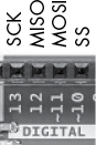
Figure 19-10: SPI pins on an Arduino Uno
A typical single Arduino-to-SPI device connection is shown in Figure 19-11. Arduino pins D11 through D13 are reserved for SPI, but the SS pin can use any other digital pin (often D10 is used because it’s next to the SPI pins).
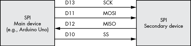
Figure 19-11: Typical Arduino-to-SPI device connection
Implementing the SPI
Now let’s examine how to implement the SPI bus in a sketch. Before doing this, however, we’ll run through the functions used. First, include the SPI library (included with the Arduino IDE software):
#include "SPI.h" Next, you need to choose a pin to be used for SS and set it as a digital output in void setup(). Because we’re using only one SPI device in our example, we’ll use D10 and set it to HIGH first, because most SPI devices have an “active low” SS pin (this means the pin is connected to GND to be set to HIGH, and vice versa):
pinMode(10, OUTPUT);
digitalWrite(10, HIGH);
Here is the function to activate the SPI bus:
SPI.begin(); Finally, we need to tell the sketch which way to send and receive data. Some SPI devices require that their data be sent with the most significant bit first, and some want the MSB last. (Again, see “A Quick Course in Binary” in Chapter 6 for more on MSB.) Therefore, in void setup(), we use the following function after SPI.begin():
SPI.setBitOrder(order);Here, order is either MSBFIRST or MSBLAST.
Sending Data to an SPI Device
To send data to an SPI device, we first set the SS pin to LOW, which tells the SPI device that the main (the Arduino) wants to communicate with it. Next, we send bytes of data to the device with the following line, as often as necessary—that is, you use this once for each byte you are sending:
SPI.transfer(byte);After you’ve finished communicating with the device, set the SS pin to HIGH to tell the device that the Arduino has finished communicating with it.
Each SPI device requires a separate SS pin. For example, if you had two SPI devices, the second SPI device’s SS pin could be D9 and connected to the Arduino as shown in Figure 19-12.

Figure 19-12: Two SPI devices connected to one Arduino
When communicating with secondary device #2, you would use the D9 (instead of the D10) SS pin before and after communication.
Project 56 demonstrates using the SPI bus with a digital rheostat.
Project #56: Using a Digital Rheostat
In simple terms, a rheostat device is similar to the potentiometers we examined in Chapter 4, except the rheostat has two pins: one for the wiper and one for the return current. In this project, you’ll use a digital rheostat to set the resistance in the sketch instead of physically turning a potentiometer knob or shaft yourself. Rheostats are often the basis of volume controls in audio equipment that use buttons rather than dials, such as a car stereo. The tolerance of a rheostat is much larger than that of a normal fixed-value resistor—in some cases, around 20 percent larger.

Figure 19-13: Microchip Technology’s MCP4162 digital rheostat
For Project 56, we will use the Microchip Technology MCP4162 shown in Figure 19-13. The MCP4162 is available in various resistance values; this example uses the 10 kΩ version. It is available from retailers such as Digi-Key (part number MCP4162-103E/P-ND) and element14 (part number 1840698). The resistance can be adjusted in 257 steps; each step has a resistance of around 40 Ω. To select a particular step, we send 2 bytes of data to a command byte (which is 0) and the value byte (which is between 0 and 256). The MCP4162 uses nonvolatile memory, so when the power is disconnected and then reconnected, the last value selected is still in effect.
We’ll control the brightness of an LED using the rheostat.
The Hardware
Here’s what you’ll need to create this project:
- Arduino and USB cable
- One breadboard
- Various connecting wires
- One Microchip Technology MCP4162 digital rheostat
- One 560 Ω resistor
- One LED
The Schematic
Figure 19-14 shows the schematic. The pin numbering on the MCP4162 starts at the top left of the package. Pin 1 is indicated by the indented dot to the left of the Microchip logo on the IC (see Figure 19-13).

Figure 19-14: Schematic for Project 56
The Sketch
Enter and upload the following sketch:
// Project 56 - Using a Digital Rheostat

1 #include "SPI.h" // necessary library
int ss=10;       // using digital pin 10 for SPI secondary select
int del=200;     // used for delaying the steps between LED brightness values

void setup()
{
2   SPI.begin();
  pinMode(ss, OUTPUT);    // we use this for the SS pin
  digitalWrite(ss, HIGH); // the SS pin is active low, so set it up high first
3   SPI.setBitOrder(MSBFIRST);
  // our MCP4162 requires data to be sent MSB (most significant byte) first
}

4 void setValue(int value)
{
  digitalWrite(ss, LOW);
  SPI.transfer(0);     // send the command byte
  SPI.transfer(value); // send the value (0 to 255)
  digitalWrite(ss, HIGH);
}

void loop()
{
5   for (int a=0; a<256; a++)
  {
    setValue(a);
    delay(del);
  }
6   for (int a=255; a>=0; a--)
  {
    setValue(a);
    delay(del);
  }
}
Let’s walk through the code. First, we set up the SPI bus at 1 and 2. At 3, we set the byte direction to suit the MPC4162. To make setting the resistance easier, we use the custom function at 4, which accepts the resistance step (0 through 255) and passes it to the MCP4162. Finally, the sketch uses two loops to move the rheostat through all the stages, from 0 to the maximum at 5 and then back to 0 at 6. This last piece should make the LED increase and decrease in brightness, fading up and down for as long as the sketch is running.
Looking Ahead
In this chapter, you learned about and experimented with two important Arduino communication methods. Now you’re ready to interface your Arduino with a huge variety of sensors, more advanced components, and other items as they become available on the market. One of the most popular components today is a real-time clock IC that allows your projects to keep and work with time—and that’s the topic of Chapter 20. So let’s go!