20
Real-Time Clocks
In this chapter you will
- Set and retrieve the time and date from a real-time clock module
- Discover new ways to connect devices to an Arduino
- Create a digital clock
- Build an employee RFID time clock
A real-time clock (RTC) IC module is a small timekeeping device that opens up all sorts of possibilities for Arduino projects. Once set with the current time and date, an RTC provides accurate time and date data on request.
You’ll find many different RTC ICs on the market, some more accurate than others. In this chapter, we’ll use the Maxim DS3231; it doesn’t require any external circuitry other than a backup battery, and it’s incredibly accurate and quite robust in module form. The DS3231 is available as a breakout board from various retailers, including the version from PMD Way (part number 883422) that is shown in Figure 20-1.

Figure 20-1: A real-time clock IC module
Connecting the RTC Module
It’s easy to connect the RTC module to an Arduino, because it uses the I2C bus (discussed in Chapter 19). All you need are four wires: GND and VCC go to Arduino GND and 5 V, respectively; SDA and SCL go to Arduino A4 and A5, respectively. We will not use the other pins in our examples. Due to the module’s design, no extra pull-up resistors are required on the I2C bus.
For convenience, consider mounting the module on a blank ProtoShield so it can be integrated easily with other hardware for other projects. And make sure you have the backup battery installed, or your time data will be lost when you turn off the project!
Project #57: Adding and Displaying Time and Date with an RTC
In this project, you’ll learn how to set the time and date on the RTC and then retrieve and display it in the Serial Monitor. Time and date information can be useful for various types of projects, such as temperature loggers and alarm clocks.
The Hardware
Here’s what you’ll need to create this project:
- Arduino and USB cable
- Various connecting wires
- One CR2032 battery (if not included with the DS3231 module)
- One Maxim DS3231 RTC module
The Sketch
Connect the module to the Arduino as described earlier in the chapter and then enter but do not upload the following sketch:
// Project 57 - Adding and Displaying Time and Date with an RTC
1 #include "Wire.h"

#define DS3231_I2C_ADDRESS 0x68

// Convert normal decimal numbers to binary coded decimal
2 byte decToBcd(byte val)
{
  return( (val/10*16) + (val%10) );
}

// Convert binary coded decimal to normal decimal numbers
byte bcdToDec(byte val)
{
  return( (val/16*10) + (val%16) );
}

3 void setDS3231time(byte second, byte minute, byte hour, byte dayOfWeek, byte
dayOfMonth, byte month, byte year)
{
  // sets time and date data in the DS3231
  Wire.beginTransmission(DS3231_I2C_ADDRESS);
  Wire.write(0); // set next input to start at the seconds register
  Wire.write(decToBcd(second));     // set seconds
  Wire.write(decToBcd(minute));     // set minutes
  Wire.write(decToBcd(hour));       // set hours
  Wire.write(decToBcd(dayOfWeek));  // set day of week (1=Sunday, 7=Saturday)
  Wire.write(decToBcd(dayOfMonth)); // set date (1 to 31)
  Wire.write(decToBcd(month));      // set month
  Wire.write(decToBcd(year));       // set year (0 to 99)
  Wire.endTransmission();
}

4 void readDS3231time(byte *second,
byte *minute,
byte *hour,
byte *dayOfWeek,
byte *dayOfMonth,
byte *month,
byte *year)
{
  Wire.beginTransmission(DS3231_I2C_ADDRESS);
  Wire.write(0); // set DS3231 register pointer to 00h
  Wire.endTransmission();
  Wire.requestFrom(DS3231_I2C_ADDRESS, 7);

  // request seven bytes of data from DS3231 starting from register 00h
  *second     = bcdToDec(Wire.read() & 0x7f);
  *minute     = bcdToDec(Wire.read());
  *hour       = bcdToDec(Wire.read() & 0x3f);
  *dayOfWeek  = bcdToDec(Wire.read());
  *dayOfMonth = bcdToDec(Wire.read());
  *month      = bcdToDec(Wire.read());
  *year       = bcdToDec(Wire.read());
}

void displayTime()
{
  byte second, minute, hour, dayOfWeek, dayOfMonth, month, year;

  // retrieve data from DS3231
5   readDS3231time(&second, &minute, &hour, &dayOfWeek, &dayOfMonth, &month,
  &year);

  // send it to the Serial Monitor
  Serial.print(hour, DEC);
  // convert the byte variable to a decimal number when displayed
  Serial.print(":");
  if (minute<10)
  {
      Serial.print("0");
  }
  Serial.print(minute, DEC);
  Serial.print(":");
  if (second<10)
  {
      Serial.print("0");
  }
  Serial.print(second, DEC);
  Serial.print("  ");
  Serial.print(dayOfMonth, DEC);
  Serial.print("/");
  Serial.print(month, DEC);
  Serial.print("/");
  Serial.print(year, DEC);
  Serial.print("  Day of week: ");
  switch(dayOfWeek){
  case 1:
    Serial.println("Sunday");
    break;
  case 2:
    Serial.println("Monday");
    break;
  case 3:
    Serial.println("Tuesday");
    break;
  case 4:
    Serial.println("Wednesday");
    break;
  case 5:
    Serial.println("Thursday");
    break;
  case 6:
    Serial.println("Friday");
    break;
  case 7:
    Serial.println("Saturday");
    break;
  }
}

void setup()
{
  Wire.begin();
  Serial.begin(9600);

  // set the initial time here:
  // DS3231 seconds, minutes, hours, day, date, month, year
6   setDS3231time(0, 56, 23, 6, 30, 10, 21);

}

void loop()
{
   displayTime(); // display the real-time clock data in the Serial Monitor,
   delay(1000);   // every second
}
Understanding and Running the Sketch
This sketch might look complex, but it’s really not so difficult. At 1, we import the I2C library and set the bus address of the RTC in the sketch as 0x68. This is the default bus address for the DS3231 and is found in the data sheet. At 2, two custom functions convert decimal numbers to binary coded decimal (BCD) values and return those values. We perform these conversions because the DS3231 stores values in BCD format.
At 6, we use the function setDS3231time() to pass the time and date information to the RTC IC like this:
setDS3231time(second, minute, hour, dayOfWeek, dayOfMonth, month, year)To use this function, simply insert the required data into the various parameters. The dayOfWeek parameter is a number between 1 and 7 representing Sunday through Saturday, respectively. (The RTC doesn’t have the ability to check whether dayOfWeek actually matches the date you enter, so take extra care to ensure everything lines up.) The information for year is only two digits—for example, you’d use 21 for the year 2021. (The 20 is assumed.) You can insert either fixed values (as in this sketch) or byte variables that contain the parameters.
Thus, to set the time in the RTC, we enter the current date and time values into the setDS3231time() function at 3. Now we can upload the sketch. Having done that once, we comment out the function by placing // in front of the setDS3231time() function at 3, and then we re-upload the sketch to ensure that the time isn’t reset to the original value every time the sketch starts!
Finally, the function readDS3231time() at 4 reads the time and date from the RTC and inserts the data into byte variables. This data is used at 5 inside the function displayTime(), which simply retrieves the data and displays it in the Serial Monitor by printing the contents of the time variables.
Once you’ve uploaded your sketch, open the Serial Monitor. The results should look similar to those shown in Figure 20-2, but they will vary to reflect the current time and date when you run the sketch.
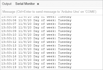
Figure 20-2: Results from Project 57
You can use the contents of the sketch for Project 57 as the basis for other time-related projects. The functions decToBcd(), bcdToDec(), readDS3231time(), and setDS3231time() can be inserted and thus reused in future projects. That’s one of the benefits of using the Arduino platform: once you write a useful procedure, it can often be reused later with little or no modification.
Project #58: Creating a Simple Digital Clock
In this project, we’ll use the functions from Project 57 to display the time and date on a standard character LCD, similar to the one used in the GPS receiver in Project 43 in Chapter 15.
The Hardware
Here’s what you’ll need to create this project:
- Arduino and USB cable
- Various connecting wires
- One breadboard
- One Proto-ScrewShield or similar product
- One LCD module or LCD shield
- One real-time clock module (shown earlier in the chapter)
First, re-create the hardware used in Project 57. If you connected the RTC module with wires into the Arduino, use a Proto-ScrewShield instead to interface with the RTC. Then insert your LCD shield on top of the other shields.
The Sketch
Enter but do not upload the following sketch:
// Project 58 - Creating a Simple Digital Clock

#include "Wire.h"
1 #include <LiquidCrystal.h>
#define DS3231_I2C_ADDRESS 0x68

LiquidCrystal lcd( 8, 9, 4, 5, 6, 7 );

// Convert normal decimal numbers to binary coded decimal
byte decToBcd(byte val)
{
  return( (val/10*16) + (val%10) );
}

// Convert binary coded decimal to normal decimal numbers
byte bcdToDec(byte val)
{
  return( (val/16*10) + (val%16) );
}

void setDS3231time(byte second, byte minute, byte hour, byte dayOfWeek, byte dayOfMonth, byte month, byte year)
{
  // sets time and date data in the DS3231
  Wire.beginTransmission(DS3231_I2C_ADDRESS);
  Wire.write(0);  // set next input to start at the seconds register
  Wire.write(decToBcd(second));     // set seconds
  Wire.write(decToBcd(minute));     // set minutes
  Wire.write(decToBcd(hour));       // set hours
  Wire.write(decToBcd(dayOfWeek));  // set day of week (1=Sunday, 7=Saturday)
  Wire.write(decToBcd(dayOfMonth)); // set date (1 to 31)
  Wire.write(decToBcd(month));      // set month
  Wire.write(decToBcd(year));       // set year (0 to 99)
  Wire.endTransmission();
}

void readDS3231time(byte *second,
byte *minute,
byte *hour,
byte *dayOfWeek,
byte *dayOfMonth,
byte *month,
byte *year)
{
  Wire.beginTransmission(DS3231_I2C_ADDRESS);
  Wire.write(0); // set DS3231 register pointer to 00h
  Wire.endTransmission();
  Wire.requestFrom(DS3231_I2C_ADDRESS, 7);

  // request seven bytes of data from DS3231 starting from register 00h
  *second     = bcdToDec(Wire.read() & 0x7f);
  *minute     = bcdToDec(Wire.read());
  *hour       = bcdToDec(Wire.read() & 0x3f);
  *dayOfWeek  = bcdToDec(Wire.read());
  *dayOfMonth = bcdToDec(Wire.read());
  *month      = bcdToDec(Wire.read());
  *year       = bcdToDec(Wire.read());
}

void displayTime()
{
  byte second, minute, hour, dayOfWeek, dayOfMonth, month, year;

  // retrieve data from DS3231
  readDS3231time(&second, &minute, &hour, &dayOfWeek, &dayOfMonth, &month,
  &year);

  // send the data to the LCD shield
  lcd.clear();
  lcd.setCursor(4,0);
  lcd.print(hour, DEC);
  lcd.print(":");
  if (minute<10)
  {
    lcd.print("0");
  }
  lcd.print(minute, DEC);
  lcd.print(":");
  if (second<10)
  {
    lcd.print("0");
  }
  lcd.print(second, DEC);

  lcd.setCursor(0,1);
  switch(dayOfWeek){
  case 1:
    lcd.print("Sun");
    break;
  case 2:
    lcd.print("Mon");
    break;
  case 3:
    lcd.print("Tue");
    break;
  case 4:
    lcd.print("Wed");
    break;
  case 5:
    lcd.print("Thu");
    break;
  case 6:
    lcd.print("Fri");
    break;
  case 7:
    lcd.print("Sat");
    break;
  }
  lcd.print(" ");
  lcd.print(dayOfMonth, DEC);
  lcd.print("/");
  lcd.print(month, DEC);
  lcd.print("/");
  lcd.print(year, DEC);
}

void setup()
{
  Wire.begin();
2   lcd.begin(16, 2);
  // set the initial time here:
  // DS3231 seconds, minutes, hours, day, date, month, year
3   // setDS3231time(0, 27, 0, 5, 15, 11, 20);
}

void loop()
{
   displayTime(); // display the real-time clock time on the LCD,
   delay(1000);   // every second
}
Understanding and Running the Sketch
The operation of this sketch is similar to that of Project 57, except in this case, we’ve altered the function displayTime() to send time and date data to the LCD instead of to the Serial Monitor, and we’ve added the setup lines required for the LCD at 1 and 2. (For a refresher on using the LCD module, see Chapter 9.)
Don’t forget to upload the sketch first with the time and date data entered at 3, and then re-upload the sketch with that code commented out. After uploading the sketch, your results should be similar to those shown in Figure 20-3.
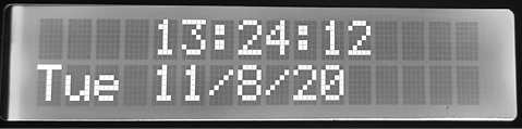
Figure 20-3: Display from Project 58
Now that you’ve worked through Projects 57 and 58, you should have a sense of how to read and write data from and to the RTC IC in your sketches. Next, you’ll use what you’ve learned so far to create something really useful.
Project #59: Creating an RFID Time-Clock System
In this project, we’ll create a time-clock system. You’ll see how Arduino shields can work together and how the Proto-ScrewShield helps you introduce electronic parts that aren’t mounted on a shield. This system can be used by two people who are assigned an RFID card or tag that they’ll swipe over an RFID reader when they enter or leave an area (such as the workplace or a home). The time and card details will be recorded to a microSD card for later analysis.
We covered logging data to a microSD card in Chapter 15, reading RFID tags in Chapter 18, and connecting to the RTC module earlier in this chapter. Now we’ll put the pieces together.
The Hardware
Here’s what you’ll need to create this project:
- Arduino and USB cable
- Various connecting wires
- One real-time clock module (shown earlier in the chapter)
- One LCD module or Freetronics LCD shield
- One microSD card shield and card (from Chapter 15)
- One Proto-ScrewShield or similar product
- One RFID reader module and two tags (from Chapter 18)
To assemble the system, start with the Arduino Uno at the bottom and then add your Proto-ScrewShield, the microSD card shield atop the ProtoScrewShield, and the LCD shield on top of the microSD card shield. Connect the RFID reader as you did in Chapter 18 and connect the RTC module as described earlier in this chapter. Depending on the exact hardware used, the assembly should look similar to that shown in Figure 20-4.
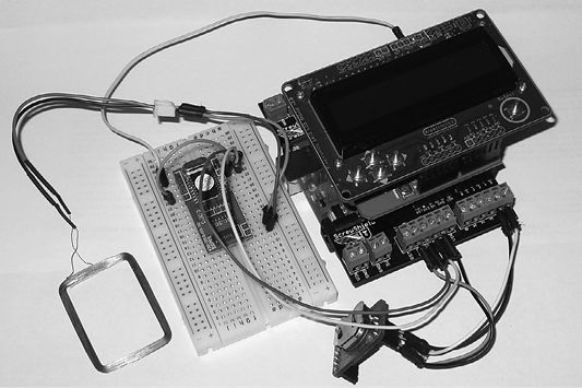
Figure 20-4: The time clock assembly
The Sketch
Now enter and upload the following sketch. Remember that when you’re uploading sketches to an RFID-connected Arduino, you need to ensure that you remove the wire between the RFID reader’s RX and Arduino pin D0, then reconnect it once the sketch has been uploaded successfully.
// Project 59 - Creating an RFID Time-Clock System

1 #include "Wire.h" // for RTC
2 #include "SD.h"   // for SD card

#include <LiquidCrystal.h>
#define DS3231_I2C_ADDRESS 0x68

LiquidCrystal lcd( 8, 9, 4, 5, 6, 7 );
int data1 = 0;

3 // Use Listing 18-1 to find your tag numbers
int Mary[14] = {
  2, 52, 48, 48, 48, 56, 54, 67, 54, 54, 66, 54, 66, 3};
int John[14] = {
  2, 52, 48, 48, 48, 56, 54, 66, 49, 52, 70, 51, 56, 3};
int newtag[14] = {
  0,0,0,0,0,0,0,0,0,0,0,0,0,0}; // used for read comparisons

// Convert normal decimal numbers to binary coded decimal
byte decToBcd(byte val)
{
  return( (val/10*16) + (val%10) );
}

// Convert binary coded decimal to normal decimal numbers
byte bcdToDec(byte val)
{
  return( (val/16*10) + (val%16) );
}

void setDS3231time(byte second, byte minute, byte hour, byte dayOfWeek, byte dayOfMonth, byte month, byte year)
{
  // Sets time and date data in the DS3231
  Wire.beginTransmission(DS3231_I2C_ADDRESS);
  Wire.write(0);  // set next input to start at the seconds register
  Wire.write(decToBcd(second));     // set seconds
  Wire.write(decToBcd(minute));     // set minutes
  Wire.write(decToBcd(hour));       // set hours
  Wire.write(decToBcd(dayOfWeek));  // set day of week (1=Sunday, 7=Saturday)
  Wire.write(decToBcd(dayOfMonth)); // set date (1 to 31)
  Wire.write(decToBcd(month));      // set month
  Wire.write(decToBcd(year));       // set year (0 to 99)
  Wire.endTransmission();
}

void readDS3231time(byte *second,
byte *minute,
byte *hour,
byte *dayOfWeek,
byte *dayOfMonth,
byte *month,
byte *year)
{
  Wire.beginTransmission(DS3231_I2C_ADDRESS);
  Wire.write(0); // set DS3231 register pointer to 00h
  Wire.endTransmission();
  Wire.requestFrom(DS3231_I2C_ADDRESS, 7);

  // Request seven bytes of data from DS3231 starting from register 00h
  *second     = bcdToDec(Wire.read() & 0x7f);
  *minute     = bcdToDec(Wire.read());
  *hour       = bcdToDec(Wire.read() & 0x3f);
  *dayOfWeek  = bcdToDec(Wire.read());
  *dayOfMonth = bcdToDec(Wire.read());
  *month      = bcdToDec(Wire.read());
  *year       = bcdToDec(Wire.read());
}

// Compares two arrays and returns true if identical.
// This is good for comparing tags.
boolean comparetag(int aa[14], int bb[14])
{
  boolean ff=false;
  int fg=0;
  for (int cc=0; cc<14; cc++)
  {
    if (aa[cc]==bb[cc])
    {
      fg++;
    }
  }
  if (fg==14)
  {
    ff=true;      // all 14 elements in the array match each other
  }
  return ff;
}

void wipeNewTag()
{
  for (int i=0; i<=14; i++)
  {
    newtag[i]=0;
  }
}

void setup()
{
  Serial.flush(); // need to flush serial buffer
  Serial.begin(9600);
  Wire.begin();
  lcd.begin(16, 2);
  // set the initial time here:
  // DS3231 seconds, minutes, hours, day, date, month, year
  // setDS3231time(0, 27, 0, 5, 15, 11, 12);
  // Check that the microSD card exists and can be used
4   if (!SD.begin(8))
  {
    lcd.print("uSD card failure");
    // stop the sketch
    return;
  }
  lcd.print("uSD card OK");
  delay(1000);
  lcd.clear();
}

}
void loop()
{
  byte second, minute, hour, dayOfWeek, dayOfMonth, month, year;

  if (Serial.available() > 0) // if a read has been attempted
  {
                 // read the incoming number on serial RX
    delay(100);  // allow time for the data to come in from the serial buffer
    for (int z=0; z<14; z++)  // read the rest of the tag
    {
      data1=Serial.read();
      newtag[z]=data1;
    }
    Serial.flush(); // stops multiple reads
                    // retrieve data from DS3231
    readDS3231time(&second, &minute, &hour, &dayOfWeek, &dayOfMonth, &month,
    &year);
  }

  // now do something based on the tag type
5   if (comparetag(newtag, Mary) == true)
  {
    lcd.print("Hello Mary ");
    File dataFile = SD.open("DATA.TXT", FILE_WRITE);
    if (dataFile)
    {
      dataFile.print("Mary ");
      dataFile.print(hour);
      dataFile.print(":");
      if (minute<10) { dataFile.print("0"); }
      dataFile.print(minute);
      dataFile.print(":");
      if (second<10) { dataFile.print("0"); }
      dataFile.print(second);
      dataFile.print(" ");
      dataFile.print(dayOfMonth);
      dataFile.print("/");
      dataFile.print(month);
      dataFile.print("/");
      dataFile.print(year);
      dataFile.println();
      dataFile.close();
    }
    delay(1000);
    lcd.clear();
    wipeNewTag();
  }

  if (comparetag(newtag, John)==true)
  {
    lcd.print("Hello John ");
    File dataFile = SD.open("DATA.TXT", FILE_WRITE);
    if (dataFile)
    {
      dataFile.print("John ");
      dataFile.print(hour);
      dataFile.print(":");
      if (minute<10) { dataFile.print("0"); }
      dataFile.print(minute);
      dataFile.print(":");
      if (second<10) { dataFile.print("0"); }
      dataFile.print(second);
      dataFile.print(" ");
      dataFile.print(dayOfMonth);
      dataFile.print("/");
      dataFile.print(month);
      dataFile.print("/");
      dataFile.print(year);
      dataFile.println();
      dataFile.close();
    }
    delay(1000);
    lcd.clear();
    wipeNewTag();
  }
}
Understanding the Sketch
In this sketch, the system first waits for an RFID card to be presented to the reader. If the RFID card is recognized, then the card owner’s name, the time, and the date are appended to a text file stored on the microSD card.
At 1 are the functions required for the I2C bus and the real-time clock, and at 2 is the line required to set up the microSD card shield. At 4, we check and report on the status of the microSD card. At 5, the card just read is compared against the stored card numbers for two people—in this case, John and Mary. If there is a match, the data is written to the microSD card. With some modification, you could add more cards to the system simply by adding the cards’ serial numbers below the existing numbers at 3 and then adding other comparison functions like those at 5.
When the time comes to review the logged data, copy the file data.txt from the microSD card. Then view the data with a text editor or import it into a spreadsheet for further analysis. The data is laid out so that it’s easy to read, as shown in Figure 20-5.

Figure 20-5: Example data generated by Project 59
Looking Ahead
In this chapter, you learned how to work with time and date data via the RTC IC. The RFID system described in Project 59 gives you the framework you need to create your own access systems or even track when, for example, your children arrive home. In the final two chapters, we’ll create projects that will use the Arduino to communicate over the internet and a cellular phone network.