
Chapter 15
Graphics with Canvas
WHAT’S IN THIS CHAPTER?
- Understanding the <canvas> element
- Drawing simple 2D graphics
- 3D drawing with WebGL
Arguably, HTML5’s most popular addition is the <canvas> element. This element designates an area of the page where graphics can be created, on the fly, using JavaScript. Originally proposed by Apple for use with its Dashboard widgets, <canvas> quickly was added into HTML5 and found a very fast adoption rate amongst browsers. Internet Explorer 9+, Firefox 1.5+, Safari 2+, Opera 9+, Chrome, Safari for iOS, and WebKit for Android all support <canvas> to some degree.
Similar to the other parts of the browser environment, <canvas> is made up of a few API sets and not all browsers support all API sets. There is a 2D context with basic drawing capabilities and a proposed 3D context called WebGL. The latest versions of the supporting browsers now support the 2D context and the text API; support for WebGL is slowly evolving, but since WebGL is still experimental, full support will likely take longer. Firefox 4+ and Chrome support early versions of the WebGL specification, though older operating systems such as Windows XP lack the necessary graphics drivers for enabling WebGL even when these browsers are present.
The <canvas> element requires at least its width and height attributes to be set in order to indicate the size of the drawing to be created. Any content appearing between the opening and closing tags is fallback data that is displayed only if the <canvas> element isn’t supported. For example:
<canvas id="drawing" width="200" height="200">A drawing of something.</canvas>
As with other elements, the width and height attributes are also available as properties on the DOM element object and may be changed at any time. The entire element may be styled using CSS as well, and the element is invisible until it is styled or drawn upon.
To begin drawing on a canvas, you need to retrieve a drawing context. A reference to a drawing context is retrieved using the getContext() method and passing in the name of the context. For example, passing "2d" retrieves a 2D context object:
var drawing = document.getElementById("drawing");

//make sure <canvas> is completely supported
if (drawing.getContext){

    var context = drawing.getContext("2d");

    //more code here
}
When using the <canvas> element, it’s important to test for the presence of the getContext() method. Some browsers create default HTML element objects for elements that aren’t officially part of HTML. In that case, the getContext() method would not be available even though drawing would contain a valid element reference.
Images created on a <canvas> element can be exported using the toDataURL() method. This method accepts a single argument, the MIME type format of the image to produce, and is applicable regardless of the context used to create the image. For example, to return a PNG-formatted image from a canvas, use the following:
var drawing = document.getElementById("drawing");

//make sure <canvas> is completely supported
if (drawing.getContext){

    //get data URI of the image
    var imgURI = drawing.toDataURL("image/png");

    //display the image
    var image = document.createElement("img");
    image.src = imgURI;
    document.body.appendChild(image);
}
2DDataUrlExample01.htm
By default, browsers encode the image as PNG unless otherwise specified. Firefox and Opera also support JPEG encoding via "image/jpeg". Because this method was added later in the process, it was adopted in later versions of supporting browsers, including Internet Explorer 9, Firefox 3.5, and Opera 10.
The toDataURL() method throws an error if an image from a different domain is drawn onto a canvas. More details are available later in this chapter.
The 2D drawing context provides methods for drawing simple 2D shapes such as rectangles, arcs, and paths. The coordinates in a 2D context begin at the upper-left of the <canvas> element, which is considered point (0,0). All coordinate values are calculated in relation to that point, with x increasing to the right and y increasing toward the bottom. By default, the width and height indicate how many pixels are available in each direction.
Fills and Strokes
There are two basic drawing operations on the 2D context: fill and stroke. Fill automatically fills in the shape with a specific style (color, gradient, or image) while stroke colors only the edges. Most of the 2D context operations have both fill and stroke variants, and how they are displayed is based on a couple of properties: fillStyle and strokeStyle.
Both properties can be set to a string, a gradient object, or a pattern object, and both default to a value of “#000000”. A string value indicates a color defined using one of the various CSS color formats: name, hex code, rgb, rgba, hsl, or hsla. For example:
var drawing = document.getElementById("drawing");

//make sure <canvas> is completely supported
if (drawing.getContext){

    var context = drawing.getContext("2d");
    context.strokeStyle = "red";
    context.fillStyle = "#0000ff";
}
This code sets the strokeStyle to “red” (a named CSS color) and fillStyle to “#0000ff” (also known as blue). All drawing operations involving stroke and fill will use these styles until the properties are changed again. These properties can also be set to a gradient or a pattern, both of which are discussed later in this chapter.
Drawing Rectangles
The only shape that can be drawn directly on the 2D drawing context is the rectangle. There are three methods for working with rectangles: fillRect(), strokeRect(), and clearRect(). Each of these methods accepts four arguments: the x-coordinate of the rectangle, the y-coordinate of the rectangle, the width of the rectangle, and the height of the rectangle. Each of these arguments is considered to be in pixels.
The fillRect() method is used to draw a rectangle that is filled with a specific color onto the canvas. The fill color is specified using the fillStyle property, for example:
var drawing = document.getElementById("drawing");

//make sure <canvas> is completely supported
if (drawing.getContext){

    var context = drawing.getContext("2d");

    /*
     * Based on Mozilla's documentation:
     * http://developer.mozilla.org/en/docs/Canvas_tutorial:Basic_usage
     */

    //draw a red rectangle
    context.fillStyle = "#ff0000";
    context.fillRect(10, 10, 50, 50);

    //draw a blue rectangle that's semi-transparent
    context.fillStyle = "rgba(0,0,255,0.5)";
    context.fillRect(30, 30, 50, 50);
}
2DFillRectExample01.htm
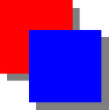
This code first sets the fillStyle to red and draws a rectangle located at (10,10) that’s 50 pixels tall and wide. Next, it sets the fillStyle to a semitransparent blue color using rgba() format and draws another rectangle that overlaps the first. The result is that you can see the red rectangle through the blue rectangle (see Figure 15-1).

The strokeRect() method draws a rectangle outline using the color specified with the strokeStyle property. Here is an example:
var drawing = document.getElementById("drawing");

//make sure <canvas> is completely supported
if (drawing.getContext){

    var context = drawing.getContext("2d");

    /*
     * Based on Mozilla's documentation:
     * http://developer.mozilla.org/en/docs/Canvas_tutorial:Basic_usage
     */

    //draw a red outlined rectangle
    context.strokeStyle = "#ff0000";
    context.strokeRect(10, 10, 50, 50);

    //draw a blue outlined rectangle that's semi-transparent
    context.strokeStyle = "rgba(0,0,255,0.5)";
    context.strokeRect(30, 30, 50, 50);
}
2DStrokeRectExample01.htm
This code also draws two rectangles that overlap; however, they are just outlines rather than filled rectangles (see Figure 15-2).

The size of the stroke is controlled by the lineWidth property, which can be set to any whole number. Likewise, a lineCap property describes the shape that should be used at the end of lines ("butt", "round", or "square") and lineJoin indicates how lines should be joined ("round", "bevel", or "miter").
You can erase an area of the canvas by using the clearRect() method. This method is used to make an area of the drawing context transparent. By drawing shapes and then clearing specific areas, you are able to create interesting effects, such as cutting out a section of another shape. Here is an example:
var drawing = document.getElementById("drawing");

//make sure <canvas> is completely supported
if (drawing.getContext){

    var context = drawing.getContext("2d");

    /*
     * Based on Mozilla's documentation:
     * http://developer.mozilla.org/en/docs/Canvas_tutorial:Basic_usage
     */

    //draw a red rectangle
    context.fillStyle = "#ff0000";
    context.fillRect(10, 10, 50, 50);

    //draw a blue rectangle that's semi-transparent
    context.fillStyle = "rgba(0,0,255,0.5)";
    context.fillRect(30, 30, 50, 50);

    //clear a rectangle that overlaps both of the previous rectangles
    context.clearRect(40, 40, 10, 10);
}
2DClearRectExample01.htm
Here, two filled rectangles overlap one another and then a small rectangle is cleared inside of that overlapping area. Figure 15-3 shows the result.

Drawing Paths
The 2D drawing context supports a number of methods for drawing paths on a canvas. Paths allow you to create complex shapes and lines. To start creating a path, you must first call beginPath() to indicate that a new path has begun. After that, the following methods can be called to create the path:
- arc(x, y, radius, startAngle, endAngle, counterclockwise)— Draws an arc centered at point (x,y) with a given radius and between startAngle and endAngle (expressed in radians). The last argument is a Boolean indicating if the startAngle and endAngle should be calculated counterclockwise instead of clockwise.
- arcTo(x1, y1, x2, y2, radius)— Draws an arc from the last point to (x2, y2), passing through (x1, y1) with the given radius.
- bezierCurveTo(c1x, c1y, c2x, c2y, x, y)— Draws a curve from the last point to the point (x, y) using the control points (c1x, c1y) and (c2x, c2y).
- lineTo(x, y) — Draws a line from the last point to the point (x, y).
- moveTo(x, y) — Moves the drawing cursor to the point (x, y) without drawing a line.
- quadraticCurveTo(cx, cy, x, y)— Draws a quadratic curve from the last point to the point (x, y) using a control point of (cx, cy).
- rect(x, y, width, height) — Draws a rectangle at point (x, y) with the given width and height. This is different from strokeRect() and fillRect() in that it creates a path rather than a separate shape.
Once the path has been created, you have several options. To draw a line back to the origin of the path, you can call closePath(). If the path is already completed and you want to fill it with fillStyle, call the fill() method. Another option is to stroke the path by calling the stroke() method, which uses strokeStyle. The last option is to call clip(), which creates a new clipping region based on the path.
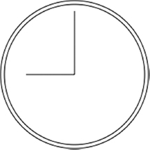
As an example, consider the following code for drawing the face of a clock without the numbers:
var drawing = document.getElementById("drawing");

//make sure <canvas> is completely supported
if (drawing.getContext){

    var context = drawing.getContext("2d");

    //start the path
    context.beginPath();

    //draw outer circle
    context.arc(100, 100, 99, 0, 2 * Math.PI, false);

    //draw inner circle
    context.moveTo(194, 100);
    context.arc(100, 100, 94, 0, 2 * Math.PI, false);

    //draw minute hand
    context.moveTo(100, 100);
    context.lineTo(100, 15);

    //draw hour hand
    context.moveTo(100, 100);
    context.lineTo(35, 100);

    //stroke the path
    context.stroke();
}
2DPathExample01.htm
This example draws two circles using arc(): an outer one and an inner one to create a border around the clock. The outer circle has a radius of 99 pixels and is centered at (100,100), which is the center of the canvas. To draw a complete circle, you must start at an angle of 0 radians and draw all the way around to 2π radians (calculated using Math.PI). Before drawing the inner circle, you must move the path to a point that will be on the circle to avoid an additional line being drawn. The second call to arc() uses a slightly smaller radius for the border effect. After that, combinations of moveTo() and lineTo() are used to draw the hour and minute hands. The last step is to call stroke(), which makes the image appear as shown in Figure 15-4.
Paths are the primary drawing mechanism for the 2D drawing context because they provide more control over what is drawn. Since paths are used so often, there is also a method called isPointInPath(), which accepts an x-coordinate and a y-coordinate as arguments. This method can be called anytime before the path is closed to determine if a point exists on the path, as shown here:
if (context.isPointInPath(100, 100)){
    alert("Point (100, 100) is in the path.");
}
The path API for the 2D drawing context is robust enough to create very complex images using multiple fill styles, stroke styles, and more.
Drawing Text
Since it’s often necessary to mix text and graphics, the 2D drawing context provides methods to draw text. There are two methods for drawing text, fillText() and strokeText(), and each takes four arguments: the string to draw, the x-coordinate, the y-coordinate, and an optional maximum pixel width to draw. Both methods base their drawing on the following three properties:
- font — Indicates the font style, size, and family in the same manner specified in CSS, such as "10px Arial".
- textAlign — Indicates how the text should be aligned. Possible values are "start", "end", "left", "right", and "center". It’s recommended to use "start" and "end" instead of "left" and "right" as these are more indicative of rendering in both left-to-right languages and right-to-left languages.
- textBaseline — Indicates the baseline of the text. Possible values are "top", "hanging", "middle", "alphabetic", "ideographic", and "bottom".
These properties have a default value, so there’s no need to set them each time you want to draw text. The fillText() method uses the fillStyle property to draw the text, whereas the strokeText() method uses the strokeStyle property. You will probably use fillText() most of the time, since this mimics normal text rendering on web pages. For example, the following renders a 12 at the top of the clock created in the previous section:
context.font = "bold 14px Arial";
context.textAlign = "center";
context.textBaseline = "middle";
context.fillText("12", 100, 20);
2DTextExample01.htm
The resulting image is displayed in Figure 15-5.
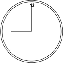
Since textAlign is set to "center" and textBaseline is set to "middle", the coordinates (100,80) indicate the horizontal and vertical center and top coordinates for the text. If textAlign were "start", then the x-coordinate would represent the left coordinate of the text in a left-to-right language while "end" would make the x-coordinate represent the right coordinate in a left-to-right language. For example:
//normal
context.font = "bold 14px Arial";
context.textAlign = "center";
context.textBaseline = "middle";
context.fillText("12", 100, 20);

//start-aligned
context.textAlign = "start";
context.fillText("12", 100, 40);

//end-aligned
context.textAlign = "end";
context.fillText("12", 100, 60);
2DTextExample02.htm
The string "12" is drawn three times, each using the same x-coordinate but with three different textAlign values. The y-coordinate values are also incremented so that the strings don’t render on top of one another. The resulting image is shown in Figure 15-6.
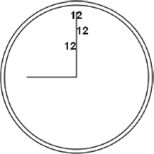
The vertical line of the clock is directly at the center so the alignment of the text becomes obvious. You can similarly adjust how the text is aligned vertically by altering textBaseline. Setting to "top" means that the y-coordinate is the top of the text, "bottom" means it’s the bottom, and "hanging", "alphabetic", and "ideographic" refer to specific baseline coordinates of a font.
Since drawing text is quite complicated, especially when you want text to render within a specific area, the 2D context provides a little extra help to determine the dimensions of text via the measureText() method. This method accepts a single argument, the text to draw, and returns a TextMetrics object. The returned object currently has only one property, width, but the intent is to provide more metrics in the future.
The measureText() method uses the current values for font, textAlign, and textBaseline to calculate the size of the specified text. For example, suppose you want to fit the text “Hello world!” within a rectangle that is 140 pixels wide. The following code starts with a font size of 100 pixels and decrements until the text fits:
var fontSize = 100;
context.font = fontSize + "px Arial";

while(context.measureText("Hello world!").width > 140){
    fontSize--;
    context.font = fontSize + "px Arial";
}

context.fillText("Hello world!", 10, 10);
context.fillText("Font size is " + fontSize + "px", 10, 50);
2DTextExample03.htm
There is also a fourth argument for both fillText() and strokeText(), which is the maximum width of the text. This argument is optional and hasn’t been implemented in all browsers yet (Firefox 4 was the first to implement it). When provided, calling fillText() or strokeText() with a string that will not fit within the maximum width results in the text being drawn with the correct character height, but the characters are scaled horizontally to fit. Figure 15-7 shows this effect.
Text drawing is one of the more complex drawing operations and, as such, not all portions of the API have been implemented in the all browsers that support the <canvas> element.
Transformations
Context transformations allow the manipulation of images drawn onto the canvas. The 2D drawing context supports all of the basic drawing transformations. When the drawing context is created, the transformation matrix is initialized with default values that cause all drawing operations to be applied directly as they are described. Applying transformations to the drawing context causes operations to be applied using a different transformation matrix and thus produces a different result.
The transformation matrix can be augmented by using any of the following methods:
- rotate(angle)— Rotates the image around the origin by angle radians.
- scale(scaleX, scaleY)— Scales the image by a multiple of scaleX in the x dimension and by scaleY in the y dimension. The default value for both scaleX and scaleY is 1.0.
- translate(x, y)— Moves the origin to the point (x, y). After performing this operation, the coordinates (0, 0) are located at the point previously described as (x, y).
- transform(m1_1, m1_2, m2_1, m2_2, dx, dy)— Changes the transformation matrix directly by multiplying by the matrix described as this:
m1_1 m1_2 dx
m2_1 m2_2 dy
0    0    1
- setTransform(m1_1, m1_2, m2_1, m2_2, dx, dy)— Resets the transformation matrix to its default state and then calls transform().
Transformations can be as simple or as complex as necessary. For example, it may be easier to draw the hands on the clock in the previous example by translating the origin to the center of the clock and then drawing the hands from there. Consider the following:
var drawing = document.getElementById("drawing");

//make sure <canvas> is completely supported
if (drawing.getContext){

    var context = drawing.getContext("2d");

    //start the path
    context.beginPath();

    //draw outer circle
    context.arc(100, 100, 99, 0, 2 * Math.PI, false);

    //draw inner circle
    context.moveTo(194, 100);
    context.arc(100, 100, 94, 0, 2 * Math.PI, false);

    //translate to center
    context.translate(100, 100);

    //draw minute hand
    context.moveTo(0,0);
    context.lineTo(0, -85);

    //draw hour hand
    context.moveTo(0, 0);
    context.lineTo(-65, 0);

    //stroke the path
    context.stroke();
}
2DTransformExample01.htm
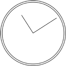
After translating the origin to (100,100), the center of the clock face, it’s just a matter of simple math to draw the lines in the same direction. All math is now based on (0,0) instead of (100,100). You can go further, moving the hands of the clock by using the rotate() method as shown here:
var drawing = document.getElementById("drawing");

//make sure <canvas> is completely supported
if (drawing.getContext){

    var context = drawing.getContext("2d");

    //start the path
    context.beginPath();

    //draw outer circle
    context.arc(100, 100, 99, 0, 2 * Math.PI, false);

    //draw inner circle
    context.moveTo(194, 100);
    context.arc(100, 100, 94, 0, 2 * Math.PI, false);

    //translate to center
    context.translate(100, 100);

    //rotate the hands
    context.rotate(1);

    //draw minute hand
    context.moveTo(0,0);
    context.lineTo(0, -85);

    //draw hour hand
    context.moveTo(0, 0);
    context.lineTo(-65, 0);

    //stroke the path
    context.stroke();
}
2DTransformExample01.htm
Since the origin has already been translated to the center of clock, the rotation is applied from that point. This means that the hands are anchored at the center and then rotated around to the right. The result is displayed in Figure 15-8.
All of these transformations, as well as properties like fillStyle and strokeStyle, remain set on the context until explicitly changed. Although there’s no way to explicitly reset everything to their default values, there are two methods that can help keep track of changes. Whenever you want to be able to return to a specific set of properties and transformations, call the save() method. Once called, this method pushes all of the settings at the moment onto a stack for safekeeping. You can then go on to make other changes to the context. When you want to go back to the previous settings, call the restore() method, which pops the settings stack and restores all of the settings. You can keep calling save() to store more settings on the stack and then systematically go back through them using restore(). Here is an example:
context.fillStyle = "#ff0000";
context.save();

context.fillStyle = "#00ff00";
context.translate(100, 100);
context.save();

context.fillStyle = "#0000ff";
context.fillRect(0, 0, 100, 200);   //draws blue rectangle at (100, 100)

context.restore();
context.fillRect(10, 10, 100, 200);   //draws green rectangle at (110, 110)

context.restore();
context.fillRect(0, 0, 100, 200);    //draws red rectangle at (0,0)
2DSaveRestoreExample01.htm
In this code, the fillStyle is set to red and then save() is called. Next, the fillStyle is changed to green, and the coordinates are translated to (100,100). Once again, save() is called to save these settings. The fillStyle property is then set to blue and a rectangle is drawn. Because the coordinates are translated, the rectangle actually ends up being drawn at (100,100). When restore() is called, fillStyle is set back to green, so the next rectangle that’s drawn is green. This rectangle is drawn at (110,110) because the translation is still in effect. When restore() is called one more time, the translation is removed and fillStyle is set back to red. The last rectangle is drawn at (0,0).
Note that save() saves only the settings and transformations applied to the drawing context but not the contents of the drawing context.
Drawing Images
The 2D drawing context has built-in support for working with images. If you have an existing image that should be drawn on the canvas, you can do so using the drawImage() method. This method can be called with three different sets of arguments based on the desired result. The simplest call is to pass in an HTML <img> element, as well as the destination x- and y-coordinates, which simply draws the image at the specified location. Here is an example:
var image = document.images[0];
context.drawImage(image, 10, 10);
2DDrawImageExample01.htm
This code gets the first image in the document and draws it on the context at position (10,10). The image is drawn in the same scale as the original. You can change how the image is drawn by adding two more arguments: the destination width and destination height. This scales the drawing without affecting the transformation matrix of the context. Here’s an example:
context.drawImage(image, 50, 10, 20, 30);
2DDrawImageExample01.htm
When this code is executed, the image is scaled to be 20 pixels wide by 30 pixels tall.
You can also select just a region of the image to be drawn onto the context. This is done by providing nine arguments to drawImage(): the image to draw, the source x-coordinate, the source y-coordinate, the source width, the source height, the destination x-coordinate, the destination y-coordinate, the destination width, and the destination height. Using this overload of drawImage() gives you the most control. Consider this example:
context.drawImage(image, 0, 10, 50, 50, 0, 100, 40, 60);
2DDrawImageExample01.htm
Here, only part of the image is drawn on the canvas. That part of the image begins at point (0,10) and is 50 pixels wide and 50 pixels tall. The image is drawn to point (0,100) on the context and scaled to fit in a 40×60 area.
These drawing operations allow you to create interesting effects such as those shown in Figure 15-9.

In addition to passing in an HTML <img> element as the first argument, you can also pass in another <canvas> element to draw the contents of one canvas onto another.
The drawImage() method, in combination with other methods, can easily be used to perform basic image manipulation, the result of which can be retrieved using toDataURL(). There is, however, one instance where this won’t work: if an image from a different origin than the page is drawn onto the context. In that case, calling toDataURL() throws an error. For example, if a page hosted on www.example.com draws an image hosted on www.wrox.com, the context is considered “dirty” and an error is thrown.
Shadows
The 2D context will automatically draw a shadow along with a shape or path based on the value of several properties:
- shadowColor — The CSS color in which the shadow should be drawn. The default is black.
- shadowOffsetX — The x-coordinate offset from the x-coordinate of the shape or path. The default is 0.
- shadowOffsetY — The y-coordinate offset from the y-coordinate of the shape or path. The default is 0.
- shadowBlur — The number of pixels to blur. If set to 0, the shadow has no blur. The default is 0.
Each of these properties can be read and written on the context object. You just need to set the values appropriately before drawing and the shadows are drawn automatically. For example:
var context = drawing.getContext("2d");

//setup shadow
context.shadowOffsetX = 5;
context.shadowOffsetY = 5;
context.shadowBlur    = 4;
context.shadowColor   = "rgba(0, 0, 0, 0.5)";

//draw a red rectangle
context.fillStyle = "#ff0000";
context.fillRect(10, 10, 50, 50);

//draw a blue rectangle
context.fillStyle = "rgba(0,0,255,1)";
context.fillRect(30, 30, 50, 50);
2DFillRectShadowExample01.htm
A shadow is drawn using the same styles for both rectangles, resulting in the image displayed in Figure 15-10.
There are some quirks with shadow support across browsers. Internet Explorer 9, Firefox 4, and Opera 11 have the correct behavior in all situations while the others have strange effects or none at all. Chrome (through version 10) will incorrectly apply a filled shadow to a stroked shape. Both Chrome and Safari (through version 5) have a problem drawing shadows for images with transparent pixels. While the shadow should be under the nontransparent parts of the image, it actually just disappears. Safari will also not apply a shadow to a gradient, while the other browsers will.
Gradients
Gradients are represented by an instance of CanvasGradient and are very simple to create and modify using the 2D context. To create a new linear gradient, call the createLinearGradient() method. This method accepts four arguments: the starting x-coordinate, the starting y-coordinate, the ending x-coordinate, and the ending y-coordinate. Once called, the method creates a new CanvasGradient object of the size you specified and returns the instance.
Once you have the gradient object, the next step is to assign color stops using the addColorStop() method. This method accepts two arguments: the location of the color stop and a CSS color. The color stop location is a number between 0 (the first color) and 1 (the last color). For example:
var gradient = context.createLinearGradient(30, 30, 70, 70);

gradient.addColorStop(0, "white");
gradient.addColorStop(1, "black");
2DFillRectGradientExample01.htm
The gradient object now represents a gradient that is drawn from point (30,30) to point (70,70) on the canvas. The starting color is white and the stopping color is black. You can now set the fillStyle or strokeStyle properties to this value to draw a shape using the gradient:
//draw a red rectangle
context.fillStyle = "#ff0000";
context.fillRect(10, 10, 50, 50);

//draw a gradient rectangle
context.fillStyle = gradient;
context.fillRect(30, 30, 50, 50);
2DFillRectGradientExample01.htm
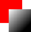
In order for the gradient to be drawn over the entire rectangle and not just part of it, the coordinates need to match up. This code produces the drawing in Figure 15-11.
If the rectangle isn’t drawn in exactly this spot, then only part of the gradient is displayed. For example:
context.fillStyle = gradient;
context.fillRect(50, 50, 50, 50);
2DFillRectGradientExample02.htm
This code creates a rectangle with only a small amount of white in the upper-left corner. That’s because the rectangle is drawn at the midpoint of the gradient, where the color transition is almost complete. The rectangle is therefore mostly black since gradients do not repeat. Keeping the gradient lined up with your shapes is important, and sometimes using a function to calculate the appropriate coordinates is useful. For example:
function createRectLinearGradient(context, x, y, width, height){
    return context.createLinearGradient(x, y, x+width, y+height);
}
2DFillRectGradientExample03.htm
This function creates a gradient based on the starting x- and y-coordinates, along with a width and height, so that the same numbers can be used as fillRect():
var gradient = createRectLinearGradient(context, 30, 30, 50, 50);

gradient.addColorStop(0, "white");
gradient.addColorStop(1, "black");

//draw a gradient rectangle
context.fillStyle = gradient;
context.fillRect(30, 30, 50, 50);
2DFillRectGradientExample03.htm
Keeping track of coordinates is an important and tricky aspect of using canvas. Helper functions such as createRectLinearGradient() can take some of the pain out of managing coordinates.
Radial gradients are created using the createRadialGradient() method. This method accepts six arguments corresponding to the center of a circle and its radius. The first three arguments define the starting circle’s center (x and y) and radius, while the last three define the same for the ending circle. When thinking about radial gradients, you will find it helps to think of a long cylinder where you’re defining the size of the circle on each end. By making one circle smaller and the other larger, you’ve effectively made a cone, and you rotate that cone around by moving the center of each circle.
To create a radial gradient that starts in the center of a shape and continues out, you need to set the center of both circles to the same origin. For example, to create a radial gradient in the center of the rectangle in the previous example, both circles must be centered at (55,55). That’s because the rectangle is drawn from point (30,30) to point (80,80). Here’s the code:
var gradient = context.createRadialGradient(55, 55, 10, 55, 55, 30);

gradient.addColorStop(0, "white");
gradient.addColorStop(1, "black");

//draw a red rectangle
context.fillStyle = "#ff0000";
context.fillRect(10, 10, 50, 50);

//draw a gradient rectangle
context.fillStyle = gradient;
context.fillRect(30, 30, 50, 50);
2DFillRectGradientExample04.htm
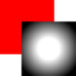
Running this code results in the drawing displayed in Figure 15-12.
Radial gradients are a little bit more difficult to work with because of the complexities of their creation, but generally you’ll end up using the same center for both starting circle and ending circle and just altering the radii of the circles for most basic effects.
Patterns
Patterns are simply repeating images that may be used to fill or stroke a shape. To create a new pattern, call the createPattern() method and pass in two arguments: an HTML <img> element and a string indicating how the image should be repeated. The second argument is the same as the values for the CSS background-repeat property: "repeat", "repeat-x", "repeat-y", and "no-repeat". For example:
var image = document.images[0],
    pattern = context.createPattern(image, "repeat");

//draw a rectangle
context.fillStyle = pattern;
context.fillRect(10, 10, 150, 150);
2DFillRectPatternExample01.htm
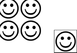
Keep in mind that, like gradients, a pattern actually starts at point (0,0) on the canvas. Setting the fill style to a pattern means revealing the pattern in the specified location rather than starting to draw at that position. This code results in a page that looks like Figure 15-13.
The first argument for createPattern() can also be a <video> element or another <canvas> element.
Working with Image Data
One of the more powerful aspects of the 2D context is the ability to retrieve raw image data using the getImageData() method. This method accepts four arguments: the left and top position of the first pixel whose data should be retrieved, and the pixel width and the pixel height to retrieve. For instance, to get image data for a 50 by 50 area starting at (10,5), use the following:
var imageData = context.getImageData(10, 5, 50, 50);
The returned object is an instance of ImageData. Each ImageData object contains just three properties: width, height, and data. The data property is an array that contains the raw pixel information for the image. Each pixel is actually represented as four items in the data array, one each for red, green, blue, and alpha. So the data for the first pixel is contained in items 0 through 3, such as:
var data = imageData.data,
    red = data[0],
    green = data[1],
    blue = data[2],
    alpha = data[3];
Each value in the array is a number between 0 and 255, inclusive. Having access to the raw image data allows you to manipulate the image in a variety of ways. For example, a simple grayscale filter can be created by changing the image data:
var drawing = document.getElementById("drawing");

//make sure <canvas> is completely supported
if (drawing.getContext){

    var context = drawing.getContext("2d"),
        image = document.images[0],
        imageData, data,
        i, len, average,
        red, green, blue, alpha;

    //draw regular size
    context.drawImage(image, 0, 0);

    //get the image data
    imageData = context.getImageData(0, 0, image.width, image.height);
    data = imageData.data;

    for (i=0, len=data.length; i < len; i+=4){

        red = data[i];
        green = data[i+1];
        blue = data[i+2];
        alpha = data[i+3];

        //get the average of rgb
        average = Math.floor((red + green + blue) / 3);

        //set the colors, leave alpha alone
        data[i] = average;
        data[i+1] = average;
        data[i+2] = average;

    }

    //assign back to image data and display
    imageData.data = data;
    context.putImageData(imageData, 0, 0);
}
2DImageDataExample01.htm
This example first draws an image onto the canvas and then retrieves its image data. A for loop iterates over each pixel in the image data. Note that each trip through the loop adds 4 to the value of i. Once the red, green, and blue values are retrieved, they are averaged together to get a new value. Then each of the values is set back to that average, effectively washing out the color and leaving only a gray of similar brightness in its place. The data array is then assigned back onto the imageData object. After that, the putImageData() method is called to draw the image data back to the canvas. The result is a grayscale version of the image.
Of course, grayscale isn’t the only type of filter that can be implemented by manipulating raw pixel values. For more information on creating filters with raw image data, see “Making Image Filters with Canvas” by Ilmari Heikkinen (www.html5rocks.com/en/tutorials/canvas/imagefilters/).
Image data is available only if the canvas isn’t dirty from loading a cross-domain resource. Attempting to access image data when the canvas is dirty causes a JavaScript error.
Compositing
There are two properties that apply to all drawing done on the 2D context: globalAlpha and globalCompositionOperation. The globalAlpha property is a number between 0 and 1, inclusive, that specifies the alpha value for all drawings. The default value is 0. If all of the upcoming drawings should be done with the same alpha, set globalAlpha to the appropriate value, perform the drawings, and then set globalAlpha back to 0. For example:
//draw a red rectangle
context.fillStyle = "#ff0000";
context.fillRect(10, 10, 50, 50);

//change the global alpha
context.globalAlpha = 0.5;

//draw a blue rectangle
context.fillStyle = "rgba(0,0,255,1)";
context.fillRect(30, 30, 50, 50);

//reset
context.globalAlpha = 0;
2DGlobalAlphaExample01.htm
In this example, a blue rectangle is drawn on top of a red rectangle. Since globalAlpha is set to 0.5 before drawing the blue rectangle, it becomes partially transparent, allowing the red rectangle to be seen through the blue.
The globalCompositionOperation property indicates how newly drawn shapes should merge with the already-existing image on the context. This property is a string value of one of the following:
- source-over (default) — New drawing is drawn on top of the existing image.
- source-in — New drawing is drawn only where it overlaps the existing image. Everything else becomes transparent.
- source-out — New drawing is drawn only where it does not overlap the existing image. Everything else becomes transparent.
- source-atop — New drawing is drawn only where it overlaps the existing image. The existing image is otherwise unaffected.
- destination-over — New drawing is drawn underneath the existing image, visible only through previously transparent pixels.
- destination-in — New drawing is drawn underneath the existing image, and all places where the two images do not overlap become transparent.
- destination-out — New drawing erases the parts of the existing image where they overlap.
- destination-atop — New drawing is drawn behind the existing image. The existing image becomes transparent where there is no overlap with new drawing.
- lighter — New drawing is drawn by combining its values with the existing image values to create a lighter image.
- copy — New drawing erases the existing image and replaces it completely.
- xor — New drawing is drawn by XORing the image data with the existing image.
The descriptions of these composite operations are difficult to represent in words or black-and-white images. For a better demonstration of each operation, see https://developer.mozilla.org/samples/canvas-tutorial/6_1_canvas_composite.html. It’s recommended to visit this site in Internet Explorer 9+ or Firefox 4+, as they have the most complete implementations of canvas. Here’s a simple example:
//draw a red rectangle
context.fillStyle = "#ff0000";
context.fillRect(10, 10, 50, 50);

//set composite operation
context.globalCompositeOperation = "destination-over";

//draw a blue rectangle
context.fillStyle = "rgba(0,0,255,1)";
context.fillRect(30, 30, 50, 50);
2DGlobalCompositeOperationExample01.htm
Even though the blue rectangle would normally be drawn over the red, changing globalComposite Operation to "destination-over" means that the red rectangle actually ends up on top of the blue.
When using globalCompositionOperation, be sure to test across a wide variety of browsers. There are still significant differences between how these operations are implemented cross-browser. Safari and Chrome still have several issues with these operations, which can be seen by going to the previously mentioned URL and comparing the rendering to that of Internet Explorer or Firefox.
WebGL is a 3D context for canvas. Unlike other web technologies, WebGL is not specified by the W3C. Instead, the Khronos Group is developing the specification. According to its website, “The Khronos Group is a not for profit, member-funded consortium focused on the creation of royalty-free open standards for parallel computing, graphics and dynamic media on a wide variety of platforms and devices.” The Khronos Group has also worked on other graphics APIs, such as OpenGL ES 2.0, which is the basis for WebGL in the browser.
3D graphics languages such as OpenGL are complex topics, and it is beyond the scope of this book to cover all concepts. Familiarity with OpenGL ES 2.0 is recommended for using WebGL as a lot of concepts map directly.
This section assumes a working knowledge of OpenGL ES 2.0 concepts and simply attempts to describe how certain parts of OpenGL ES 2.0 have been implemented in WebGL. For more information on OpenGL, please visit www.opengl.org and for an excellent series of WebGL tutorials, please visit www.learningwebgl.com.
Typed Arrays
Since WebGL deals with complex calculations requiring predictable precision, standard JavaScript numbers do not work. Instead, WebGL introduces the concept of typed arrays, which are arrays whose items are set to be values of a particular type.
At the core of typed arrays is a type called ArrayBuffer. An ArrayBuffer object represents a specified number of bytes in memory but does not specify the type to treat the bytes. All you can do with an ArrayBuffer is allocate a certain number of bytes for use. For example, the following allocates 20 bytes:
var buffer = new ArrayBuffer(20);
Once the ArrayBuffer is created, all you can do with the object itself is retrieve the number of bytes contained within by accessing the byteLength property:
var bytes = buffer.byteLength;
Although the ArrayBuffer object itself isn’t very interesting, its use is extremely important to WebGL and is made more interesting when you use views.
Views
An array buffer view is a particular way of using the bytes within an array buffer. The most generic view is DataView, which allows you to select a subset of bytes in an ArrayBuffer. To do so, create a new instance of DataView and pass in the ArrayBuffer, an optional byte offset from which to select, and an optional number of bytes to select. For example:
//create a new view over the entire buffer
var view = new DataView(buffer);

//create a new view starting with byte 9
var view = new DataView(buffer, 9);

//create a new view going from byte 9 to byte 18
var view = new DataView(buffer, 9, 10);
Once instantiated, a DataView keeps the byte offset and length information in the byteOffset and byteLength properties, respectively:
alert(view.byteOffset);
alert(view.byteLength);
These properties let you easily inspect the view later on. You can also retrieve the array buffer through the buffer property.
Reading and writing to the DataView are done through a series of getter and setter methods based on the type of data you’re working with. The following table lists the supported data types and their associated methods:
| DATA TYPE | GETTER | SETTER |
| Signed 8-bit integer | getInt8(byteOffset) | setInt8(byteOffset, value) |
| Unsigned 8-bit integer | getUint8(byteOffset) | setUint8(byteOffset, value) |
| Signed 16-bit integer | getInt16(byteOffset, littleEndian) | setInt16(byteOffset, value, littleEndian) |
| Unsigned 16-bit integer | getUint16(byteOffset, littleEndian) | setUint16(byteOffset, value, littleEndian) |
| Signed 32-bit integer | getInt32(byteOffset, littleEndian) | setInt32(byteOffset, value, littleEndian) |
| Unsigned 32-bit integer | getUint32(byteOffset, littleEndian) | setUint32(byteOffset, value, littleEndian) |
| 32-bit float | getFloat32(byteOffset, littleEndian) | setFloat32(byteOffset, value, littleEndian) |
| 64-bit float | getFloat64(byteOffset, littleEndian) | setFloat64(byteOffset, value, littleEndian) |
Each method expects the first argument to be the byte offset to retrieve from or write to. Keep in mind that, depending on the data type, the data may take more than one byte to store. An unsigned 8-bit integer takes one byte to store while a 32-bit float takes four bytes. Using a DataView, you’ll need to manage this yourself by ensuring you know exactly how many bytes your data needs and using the correct method. For example:
var buffer = new ArrayBuffer(20),
    view = new DataView(buffer),
    value;

view.setUint16(0, 25);
view.setUint16(2, 50);   //don't start at 1, 16-bit integers take two bytes
value = view.getUint16(0);
DataViewExample01.htm
This code saves two unsigned 16-bit integers into the array buffer. Since each 16-bit integer takes two bytes, the first number is stored at byte offset 0 while the second is stored at byte offset 2.
Each method dealing with 16-bit or larger numbers has an optional argument called littleEndian. This is a Boolean value indicating if the value should be read or written as little-endian (least significant byte is the first byte) instead of big-endian (least significant byte is the last byte). If you’re not sure which to use, then leave off this option to use the default big-endian storage pattern.
Because you’re dealing with byte offsets rather than item numbers, it’s possible to access the same bytes in different ways. For example:
var buffer = new ArrayBuffer(20),
    view = new DataView(buffer),
    value;

view.setUint16(0, 25);
value = view.getInt8(0);

alert(value);    //0
DataViewExample02.htm
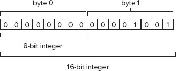
In this example, the number 25 is written into a 16-bit unsigned integer beginning at byte offset 0. An attempt to read the value as an 8-bit signed integer results in a return value of 0. That’s because the binary form of 25 has all zeros in the first byte (see Figure 15-14).
So while the DataView gives you access to byte-level data in an array buffer, you’ll need to keep track of where data is being stored and how many bytes it needs to do so. This can be a lot of work, and so typed views are also available.
Typed Views
The typed views are typically referred to as typed arrays because they act like regular arrays with the exception that their elements must be of a particular data type. There are several typed views, and all of them inherit from DataView:
- Int8Array — Represents numbers as 8-bit two’s complement integers.
- Uint8Array — Represents numbers as 8-bit unsigned integers.
- Int16Array — Represents numbers as 16-bit two’s complement integers.
- Uint16Array — Represents numbers as 16-bit unsigned integers.
- Int32Array — Represents numbers as 32-bit two’s complement integers.
- Uint32Array — Represents numbers as 32-bit unsigned integers.
- Float32Array — Represents numbers as 32-bit IEEE floating-point values.
- Float64Array — Represents numbers as 64-bit IEEE floating-point values.
Each view represents data in a different way, and each piece of data may take one or more bytes to represent. For example, an ArrayBuffer of 20 bytes will hold 20 values in Int8Array or Uint8Array; 10 values in Int16Array or Uint16Array; 5 values in Int32Array, Uint32Array, or Float32Array; or two values in Float64Array.
Since each of these types inherits from DataView, you can instantiate them using the same constructor arguments: the ArrayBuffer object to use, the starting byte offset (0 by default), and the number of bytes to include. Only the first argument is required. Some examples:
//create a new array that uses the whole buffer
var int8s = new Int8Array(buffer);

//only use bytes starting at byte 9
var int16s = new Int16Array(buffer, 9);

//only use bytes starting at 9 going through 18
var uint16s = new Uint16Array(buffer, 9, 10);
Being able to specify a subset of a buffer means that you can store different numeric types within the same buffer. For example, the following allows storing of 8-bit integers at the start of the buffer and 16-bit integers in the rest:
//use part of the buffer for 8-bit integers, part for 16-bit
var int8s = new Int8Array(buffer, 0, 10);
var uint16s = new Uint16Array(buffer, 11, 10);
Each view constructor has a property called BYTES_PER_ELEMENT that indicates how many bytes each element of a typed array requires. So Uint8Array.BYTES_PER_ELEMENT is 1 while Float32Array.BYTES_PER_ELEMENT is 4. You can use this to help initialize a view:
//need space for 10 items
var int8s = new Int8Array(buffer, 0, 10 * Int8Array.BYTES_PER_ELEMENT);

//need space for 5 items
var uint16s = new Uint16Array(buffer, int8s.byteOffset + int8s.byteLength,
                              5 * Uint16Array.BYTES_PER_ELEMENT);
This example creates two views onto an array buffer. The first 10 bytes are used for storing 8-bit integers while the rest are used to store unsigned 16-bit integers. The Uint16Array uses the byteOffset and byteLength properties of the Int8Array to ensure the view starts after the 8-bit data.
Since the point of typed views are to make working with binary data easier, you can also create a new typed view without first creating an ArrayBuffer object. Just pass in the number of items you’d like the array to hold, and an ArrayBuffer will be automatically created with the correct number of bytes. For example:
//create an array for 10 8-bit integers (10 bytes)
var int8s = new Int8Array(10);

//create an array for 10 16-bit integers (20 bytes)
var int16s = new Int16Array(10);
Regular arrays can also be converted into typed views by passing them into a typed view constructor:
//create an array for 5 8-bit integers (10 bytes)
var int8s = new Int8Array([10, 20, 30, 40, 50]);
This is the best way to initialize typed views with default values and is used quite frequently with WebGL projects.
Using typed views in this way makes them more like regular Array objects and ensures that the proper data types are used when reading or writing information.
When using a typed view, you can access data members using bracket notation and use the length property to determine how many items are present. This makes iterating over typed views exactly the same as iterating over Array objects:
for (var i=0, len=int8s.length; i < len; i++){
    console.log("Value at position " + i + " is " + int8s[i]);
}
Values can also be assigned to spots in a typed view using bracket notation. If the value doesn’t fit within the specified number of bytes for an item, the number is stored as the modulo of the largest possible number. For example, the largest number that can be represented as an unsigned 16-bit integer is 65535. If you attempt to store 65536, it becomes 0; attempting to store 65537 yields 1, and so on:
var uint16s = new Uint16Array(10);
uint16s[0] = 65537;
alert(uint16s[0]);  //1
No errors are thrown when data types don’t match, so you must be certain that numbers fit within their byte limits.
Typed views have one additional method called subarray(), which allows you to create a new view on a subset of the underlying array buffer. This method accepts two arguments, the item index to start with and an optional item index to end with. The returned type is the same as the type on which the method was called. For example:
var uint16s = new Uint16Array(10),
    sub = uint16s.subarray(2, 5);
In this code, sub is also an instance of Uint16Array and is a view into the same ArrayBuffer object as uint16s. The advantage of subarrays is in allowing access to a smaller number of items in a larger array without fear of unintentionally modifying other items.
Typed arrays are an important part of performing operations in WebGL.
The WebGL Context
The WebGL context name in supporting browsers is currently "experimental-webgl", as the WebGL specification is still under development. Once development is complete, the context name will simply be "webgl". If the browser doesn’t support WebGL, then attempting to retrieve a WebGL context returns null. You should always check the returned value before attempting to use the context:
var drawing = document.getElementById("drawing");

//make sure <canvas> is completely supported
if (drawing.getContext){

    var gl = drawing.getContext("experimental-webgl");
    if (gl){
        //proceed with WebGL
    }
}
WebGLExample01.htm
The WebGL context object is typically called gl. Most WebGL applications and examples use this convention because OpenGL ES 2.0 methods and values typically begin with "gl". Doing so means the JavaScript code reads more closely like an OpenGL program.
Once the WebGL context is established, you’re ready to start 3D drawing. As mentioned previously, since WebGL is a web version of OpenGL ES 2.0, the concepts discussed in this section are really OpenGL concepts as implemented in JavaScript.
You can specify options for the WebGL context by passing in a second argument to getContext(). The argument is an object containing one or more of the following properties:
- alpha — When set to true, creates an alpha channel buffer for the context. Default is true.
- depth — When set to true, a 16-bit depth buffer is available. Default is true.
- stencil — When set to true, an 8-bit stencil buffer is available. Default is false.
- antialias — When set to true, antialiasing will be performed using the default mechanism. Default is true.
- premultipliedAlpha — When set to true, the drawing buffer is assumed to have premultipled alpha values. Default is true.
- preserveDrawingBuffer — When set to true, the drawing buffer is preserved after drawing is completed. Default is false. Recommended to change only if you know exactly what this does, as there may be performance implications.
The options object is passed in like this:
var drawing = document.getElementById("drawing");

//make sure <canvas> is completely supported
if (drawing.getContext){

    var gl = drawing.getContext("experimental-webgl", { alpha: false});
    if (gl){
        //proceed with WebGL
    }
}
WebGLExample01.htm
Most of the context options are for advanced use. In many cases, the default values will serve your purpose.
Some browsers may throw an error if the WebGL context can’t be created via getContext(). For that reason, it’s best to wrap the call in a try-catch block:
Insert IconMargin [download]var drawing = document.getElementById("drawing"),
    gl;

//make sure <canvas> is completely supported
if (drawing.getContext){
    try {
        gl = drawing.getContext("experimental-webgl");
    } catch (ex) {
        //noop
    }

    if (gl){
        //proceed with WebGL
    } else {
        alert("WebGL context could not be created.");
    }
}
WebGLExample01.htm
Constants
If you’re familiar with OpenGL, then you’re familiar with the large number of constants used for operations. These constants are named in OpenGL with a prefix of GL_. In WebGL, each constant is available on the WebGL context object without the GL_ prefix. For example, the GL_COLOR_BUFFER_BIT constant is available as gl.COLOR_BUFFER_BIT. WebGL supports most OpenGL constants in this manner (some constants are not available).
Method Naming
Many method names in OpenGL, and so also in WebGL, tend to include information about the type of data to be used with the method. If a method can accept different types and numbers of arguments then it is suffixed to indicate the expected input. The method will indicate the number of arguments (1 through 4) followed by the data type (“f” for float and “i” for int). For example, gl.uniform4f() expects four floats to be passed in and gl.uniform3i() expects three integers to be passed in.
Many methods also allow an array to be passed in instead of individual arguments. This is indicated by the letter “v,” which is short for vector. So gl.uniform3iv() accepts an array of integers with three values. Keep this convention in mind throughout the discussion of WebGL.
Getting Ready to Draw
One of the first steps when working on a WebGL context is to clear the <canvas> with a solid color to prepare for drawing. To do this, you first must assign the color to use via the clearColor() method. This method accepts four arguments: red, green, blue, and alpha. Each argument must be a number between 0 and 1 defining the strength of value as part of a final color. Consider the following example:
gl.clearColor(0,0,0,1);    //black
gl.clear(gl.COLOR_BUFFER_BIT);
WebGLExample01.htm
This code sets the clear color buffer value to black and then calls the clear() method, which is the equivalent of glClear() in OpenGL. Providing the argument gl.COLOR_BUFFER_BIT tells WebGL to use the previously defined color to fill the area. Generally speaking, all drawing operations begin with a call to clear the area for drawing.
Viewports and Coordinates
To get started, it’s a good idea to define the WebGL viewport. By default, the viewport is set to use the entire <canvas> area. To change the viewport, call the viewport() method and pass in the x, y, width, and height of the viewport relative to the <canvas> element. For example, this call uses the entire <canvas> element:
gl.viewport(0, 0, drawing.width, drawing.height);
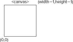
The viewport is defined using a different coordinate system than is typically used in a web page. The x- and y-coordinates start with (0,0) at the bottom-left of the <canvas> element and increase toward the top and right, which can be defined as point (width–1, height–1) (see Figure 15-15).
Knowing how the viewport is defined allows you to use just a part of the <canvas> element for drawing. Consider the following examples:
//viewport is a quarter of the <canvas> in the lower-left corner
gl.viewport(0, 0, drawing.width/2, drawing.height/2);

//viewport is a quarter of the <canvas> in the upper-left corner
gl.viewport(0, drawing.height/2, drawing.width/2, drawing.height/2);

//viewport is a quarter of the <canvas> in the lower-right corner
gl.viewport(drawing.width/2, 0, drawing.width/2, drawing.height/2);
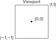
The coordinate system within a viewport is different than the coordinate system for defining a viewport. Inside of a viewport, the coordinates start with point (0,0) in the center of the viewport. The lower-left corner is (–1,–1) while the upper-right is (1,1) (see Figure 15-16).
If a coordinate outside of the viewport is used for a drawing operation then the drawing is clipped along the viewport. For instance, attempting to draw a shape with a vertex at (1,2) will result in a shape that is cut off on the right side of the viewport.
Buffers
Vertex information is stored in typed arrays in JavaScript and must be converted into WebGL buffers for use. Buffers are created by calling gl.createBuffer() and then bound to the WebGL context using gl.bindBuffer(). Once that happens, you can fill the buffer with data. For example:
var buffer = gl.createBuffer();
gl.bindBuffer(gl.ARRAY_BUFFER, buffer);
gl.bufferData(gl.ARRAY_BUFFER, new Float32Array([0, 0.5, 1]), gl.STATIC_DRAW);
The call to gl.bindBuffer() sets buffer as the current buffer for the context. After that point, all buffer operations are performed on buffer directly. So the call to gl.bufferData() doesn’t contain a direct reference to buffer but works on it nonetheless. That last line initializes buffer with information from a Float32Array (you generally will be using Float32Array for all vertex information). You can also use gl.ELEMENT_ARRAY_BUFFER if you intend to use drawElements() for outputting the buffer content.
The last argument of gl.bufferData() indicates how the buffer will be used. This is one of the following constants:
- gl.STATIC_DRAW — The data will be loaded once and used for drawing multiple times.
- gl.STREAM_DRAW — The data will be loaded once and used for drawing just a few times.
- gl.DYNAMIC_DRAW — The data will be modified repeatedly and used for drawing multiple times.
You’ll likely use gl.STATIC_DRAW for most buffers unless you’re an experienced OpenGL programmer.
Buffers stay in memory until the containing page is unloaded. If you no longer need a buffer, then it’s best to free its memory by calling gl.deleteBuffer():
gl.deleteBuffer(buffer);
Errors
One of the differences between most JavaScript and WebGL is that errors are generally not thrown from WebGL operations. Instead, you must call the gl.getError() method after invoking a method that may have failed. This method returns a constant value indicating the type of error that has occurred. The constants are as follows:
- gl.NO_ERROR — There wasn’t an error during the last operation (value of 0).
- gl.INVALID_ENUM — An incorrect argument was passed to a method that was expecting one of the WebGL constants.
- gl.INVALID_VALUE — A negative number was passed where only an unsigned number is accepted.
- gl.INVALID_OPERATION — The operation cannot be completed in the current state.
- gl.OUT_OF_MEMORY — There is not enough memory to complete the operation.
- gl.CONTEXT_LOST_WEBGL — The WebGL context was lost because of an external event (such as loss of power on a device).
Each call to gl.getError() returns a single error value. After the initial call, the next call to gl.getError() may return another error value. If there are multiple errors, then this process continues until gl.getError() returns gl.NO_ERROR. If you have performed a number of operations, then you’ll likely want to call getError() in a loop, such as:
var errorCode = gl.getError();
while(errorCode){
    console.log("Error occurred: " + errorCode);
    errorCode = gl.getError();
}
If your WebGL script is not resulting in the correct output, then putting a few calls to gl.getError() into your script may help debug the issue.
Shaders
Shaders are another concept from OpenGL. There are two types of shaders in WebGL: vertex shaders and fragment shaders. Vertex shaders are used to convert a 3D vertex into a 2D point to be rendered. Fragment shaders are used to compute the correct color for drawing a single pixel. The unique and challenging aspect of WebGL shaders is that they are not written in JavaScript. Shaders are written using OpenGL Shading Language (GLSL), a completely separate language from C or JavaScript.
Writing Shaders
GLSL is a C-like language that is used specifically for defining OpenGL shaders. Since WebGL is an implementation of OpenGL ES 2, the shaders used in OpenGL can be used directly in WebGL, allowing for easy porting of desktop graphics to the Web.
Each shader has a method called main() that is executed repeatedly during drawing. There are two ways to pass data into a shader: attributes and uniforms. Attributes are used to pass vertices into a vertex shader while uniforms are used to pass constant values to either type of shader. Attributes and uniforms are defined outside of main() by using the keywords attribute or uniform, respectively. After the value type keyword, the data type is specified followed by a name. Here’s a simple example vertex shader:
//OpenGL Shading Language
//Shader by Bartek Drozdz in his article at
//http://www.netmagazine.com/tutorials/get-started-webgl-draw-square
attribute vec2 aVertexPosition;

void main() {
        gl_Position = vec4(aVertexPosition, 0.0, 1.0);
}
WebGLExample02.htm
This vertex shader defines a single attribute called aVertexPosition. This attribute is an array of two items (vec2 data type) representing an x- and y-coordinate. A vertex shader must always result in a four-part vertex being assigned to the special variable gl_Position even though only two coordinates were passed. This shader creates a new four-item array (vec4) and fills in the missing coordinates, effectively turning a 2D coordinate into a 3D one.
Fragment shaders are similar to vertex shaders except you can pass data only in via uniforms. Here’s an example fragment shader:
//OpenGL Shading Language
//Shader by Bartek Drozdz in his article at
//http://www.netmagazine.com/tutorials/get-started-webgl-draw-square
uniform vec4 uColor;

void main() {
        gl_FragColor = uColor;
}
WebGLExample02.htm
Fragment shaders must result in a value being assigned to gl_FragColor, which indicates the color to use while drawing. This shader defined a uniform four-part (vec4) color named uColor to be set. Literally, this shader does nothing but assign the passed-in value to gl_FragColor. The value of uColor cannot be changed within the shader.
OpenGL Shading Language is a more complex language than represented here. There are entire books devoted to explaining the intricacies of the languages, and so this section is just a quick introduction to the language as a way of facilitating WebGL usage. For more information, please read OpenGL Shading Language by Randi J. Rost (Addison-Wesley, 2006).
Creating Shader Programs
GLSL cannot be natively understood by a browser, so you must have a string of GLSL ready for compilation and linking into a shader program. For ease of use, shaders are typically included in a page using <script> elements with a custom type attribute. Using an invalid type attribute prevents the browser from attempting to interpret the <script> contents while allowing you easy access. For example:
<script type="x-webgl/x-vertex-shader" id="vertexShader">
attribute vec2 aVertexPosition;

void main() {
        gl_Position = vec4(aVertexPosition, 0.0, 1.0);
}
</script>
<script type="x-webgl/x-fragment-shader" id="fragmentShader">
uniform vec4 uColor;

void main() {
        gl_FragColor = uColor;
}
</script>
WebGLExample02.htm
You can then extract the contents of the <script> element using the text property:
var vertexGlsl = document.getElementById("vertexShader").text,
    fragmentGlsl = document.getElementById("fragmentShader").text;
More complex WebGL applications may choose to download shaders dynamically using Ajax (discussed in Chapter 21). The important aspect is that you need a GLSL string in order to use a shader.
Once you have a GLSL string, the next step is to create a shader object. This is done by calling the gl.createShader() method and passing in the type of shader to create (gl.VERTEX_SHADER or gl.FRAGMENT_SHADER). After that, the source code of the shader is applied using gl.shaderSource() and the shader is compiled using gl.compileShader(). Here’s an example:
var vertexShader = gl.createShader(gl.VERTEX_SHADER);
gl.shaderSource(vertexShader, vertexGlsl);
gl.compileShader(vertexShader);

var fragmentShader = gl.createShader(gl.FRAGMENT_SHADER);
gl.shaderSource(fragmentShader, fragmentGlsl);
gl.compileShader(fragmentShader);
WebGLExample02.htm
This code creates two shaders and stores them in vertexShader and fragmentShader. These two objects can then be linked into a shader program by using the following code:
var program = gl.createProgram();
gl.attachShader(program, vertexShader);
gl.attachShader(program, fragmentShader);
gl.linkProgram(program);
WebGLExample02.htm
The first line creates a program and then attachShader() is used to include the two shaders. The call to gl.linkProgram() encapsulates both shaders together into the variable program. With the program linked, you can instruct the WebGL context to use the program via the gl.useProgram() method:
gl.useProgram(program);
After gl.useProgram() has been called, all further drawing operations will use the specified program.
Passing Values to Shaders
Each of the previously defined shaders has a value that must be passed in to complete the shader’s job. To pass values into a shader, you must first locate the variable whose value must be filled. For uniform variables, this is done through gl.getUniformLocation(), which returns an object representing the location of the uniform variable in memory. You can then use this location to assign data. For example:
var uColor = gl.getUniformLocation(program, "uColor");
gl.uniform4fv(uColor, [0, 0, 0, 1]);
WebGLExample02.htm
This example locates the uniform variable uColor in program and returns its memory location. The second line assigns a value into uColor using gl.uniform4fv().
A similar process is followed for attribute variables in vertex shaders. To get the location of an attribute variable, use gl.getAttribLocation(). Once the location is retrieved, it can be used as in this example:
var aVertexPosition = gl.getAttribLocation(program, "aVertexPosition");
gl.enableVertexAttribArray(aVertexPosition);
gl.vertexAttribPointer(aVertexPosition, itemSize, gl.FLOAT, false, 0, 0);
WebGLExample02.htm
Here, the location of aVertexPosition is retrieved so that it may be enabled for use via gl.enableVertexAttribArray(). The last line creates a pointer into the last buffer specified using gl.bindBuffer() and stores it in aVertexPosition so that it may be used by the vertex shader.
Debugging Shaders and Programs
As with other operations in WebGL, shader operations may fail and will do so silently. You need to manually ask the WebGL context for information about the shader or program if you think there has been an error.
For shaders, call gl.getShaderParameter() to get the compiled status of the shader after attempting compilation:
if (!gl.getShaderParameter(vertexShader, gl.COMPILE_STATUS)){
    alert(gl.getShaderInfoLog(vertexShader));
}
WebGLExample02.htm
This example checks the compilation status of vertexShader. If the shader compiled successfully, then the call to gl.getShaderParameter() returns true. If the call returns false, then there was an error during compilation and you can retrieve the error by using gl.getShaderInfoLog() and passing in the shader. This method returns a string message indicating the issue. Both gl.getShaderParameter() and gl.getShaderInfoLog() may be used on vertex shaders and fragment shaders.
Programs may also fail and have a similar method, gl.getProgramParameter(), to check status. The most common program failure is during the linking process, for which you would check using the following code:
if (!gl.getProgramParameter(program, gl.LINK_STATUS)){
    alert(gl.getProgramInfoLog(program));
}
WebGLExample02.htm
As with gl.getShaderParameter(), the gl.getProgramParameter() returns either true to indicate that the link succeeded or false to indicate it failed. There is also gl.getProgramInfoLog(), which is used to get information about the program during failures.
These methods are primarily used during development to aid in debugging. As long as there are no external dependencies, it’s safe to remove them in production.
Drawing
WebGL can draw only three types of shapes: points, lines, and triangles. All other shapes must be composed using a combination of these three basic shapes drawn in three-dimensional space. Drawing is executed by using the drawArrays() or drawElements() methods; the former works on array buffers while the latter acts on element array buffers.
The first argument for both gl.drawArrays() and drawElements() is a constant indicating the type of shape to draw. The constants are:
- gl.POINTS — Treats each vertex as a single point to be drawn.
- gl.LINES — Treats the array as a series of vertices between which to draw lines. Each set of vertices is a start point and an end point, so you must have an even number of vertices in the array for all drawing to take place.
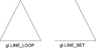
- gl.LINE_LOOP — Treats the array as a series of vertices between which to draw lines. The line is drawn from the first vertex to the second, from the second to the third, etc., until the last vertex is reached. A line is then drawn from the last vertex to the first vertex. This effectively creates an outline of a shape.
- gl.LINE_STRIP — Same as gl.LINE_LOOP except a line is not drawn from the last vertex back to the first.
- gl.TRIANGLES — Treats the array as a series of vertices within which triangles should be drawn. Each triangle is drawn separately from the previous without sharing vertex unless explicitly specified.
- gl.TRIANGLES_STRIP — Same as gl.TRIANGLES except vertices after the first three are treated as the third vertex for a new triangle made with the previous two vertices. For example, if an array contains vertices A, B, C, D, the first triangle is drawn as ABC while the second is drawn as BCD.
- gl.TRIANGLES_FAN — Same as gl.TRIANGLES except vertices after the first three are treated as the third vertex for a triangle made with the previous vertex and the first coordinate. For example, if an array contains vertices A, B, C, D, the first triangle is drawn as ABC while the second is drawn as ACD.
The gl.drawArrays() method accepts one of these values as its first argument, the starting index within the array buffer as the second argument, and the number of sets contained in the array buffer as the third argument. The following code uses gl.drawArrays() to draw a single triangle across the canvas:
//assume viewport is cleared using the shaders from earlier in the section

//define three vertices, x and y for each
var vertices = new Float32Array([ 0, 1, 1, -1, -1, -1 ]),
    buffer = gl.createBuffer(),
    vertexSetSize = 2,
    vertexSetCount = vertices.length/vertexSetSize,
    uColor, aVertexPosition;

//put data into the buffer
gl.bindBuffer(gl.ARRAY_BUFFER, buffer);
gl.bufferData(gl.ARRAY_BUFFER, vertices, gl.STATIC_DRAW);

//pass color to fragment shader
uColor = gl.getUniformLocation(program, "uColor");
gl.uniform4fv(uColor, [ 0, 0, 0, 1 ]);

//pass vertex information to shader
aVertexPosition = gl.getAttribLocation(program, "aVertexPosition");
gl.enableVertexAttribArray(aVertexPosition);
gl.vertexAttribPointer(aVertexPosition, vertexSetSize, gl.FLOAT, false, 0, 0);

//draw the triangle
gl.drawArrays(gl.TRIANGLES, 0, vertexSetCount);
WebGLExample02.htm
This example defines a Float32Array containing three sets of two-point vertices. It’s important to keep track of the size and number of vertex sets for use in later calculations. The vertexSetSize is set to 2 while the vertexSetCount is calculated. The vertex information is stored in a buffer. Color information is then passed to the fragment shader.
The vertex shader is passed the size of the vertex set and indicates that the vertex coordinates are floats (gl.FLOAT). The fourth argument is a Boolean indicating that the coordinates are not normalized. The fifth argument is the stride value, which indicates how many array items need to be skipped to get the next value. This is 0 unless you really know what you’re doing. The last argument is the starting offset, which is 0 to start at the first item.
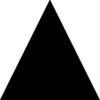
The last step is to draw the triangle by using gl.drawArrays(). By specifying the first argument as gl.TRIANGLES, a triangle will be drawn from (0,1) to (1,–1) to (–1,–1) and filled in with the color passed to the fragment shader. The second argument is the starting offset in the buffer, and the last argument is the total number of vertex sets to read. The result of this drawing operation is displayed in Figure 15-17.
By changing the first argument to gl.drawArrays(), you can change how the triangle is drawn. Figure 15-18 shows some other possible outputs based on changing the first argument.
Textures
WebGL textures work together with images from the DOM. You create a new texture using gl.createTexture() and then bind an image to that texture. If the image isn’t already loaded, then you may create a new instance of Image to dynamically load it. A texture isn’t initialized until the image is completely loaded, so texture setup steps must be done after the load event has fired. For example:
var image = new Image(),
    texture;
image.src = "smile.gif";
image.onload = function(){
    texture = gl.createTexture();
    gl.bindTexture(gl.TEXTURE_2D, texture);
    gl.pixelStorei(gl.UNPACK_FLIP_Y_WEBGL, true);

    gl.texImage2D(gl.TEXTURE_2D, 0, gl.RGBA, gl.RGBA, gl.UNSIGNED_BYTE, image);
    gl.texParameteri(gl.TEXTURE_2D, gl.TEXTURE_MAG_FILTER, gl.NEAREST);
    gl.texParameteri(gl.TEXTURE_2D, gl.TEXTURE_MIN_FILTER, gl.NEAREST);

    //clear current texture
    gl.bindTexture(gl.TEXTURE_2D, null);
}
Aside from using a DOM image, these steps are the same for creating texture in OpenGL. The biggest difference is in setting the pixel storage format with gl.pixelStorei(). The constant gl.UNPACK_FLIP_Y_WEBGL is unique to WebGL and must be used in most circumstances when loading Web-based images. This is because of the different coordinate systems used by GIF, JPEG, and PNG images as compared to the internal coordinate system of WebGL. Without this flag, the image is interpreted upside down.
Images used for textures must be of the same origin as the containing page or else exist on servers that have Cross-Origin Resource Sharing (CORS) enabled for the images. CORS is discussed in Chapter 21.
Texture sources may be images, videos loaded into the <video> element, and even another <canvas> element. The same restrictions regarding cross-origin resources apply to videos.
Reading Pixels
As with the 2D context, it’s possible to read pixels from the WebGL context. The readPixels() method has the same arguments as in OpenGL with the exception that the last argument must be a typed array. Pixel information is read from the frame buffer and placed into the typed array. The arguments for readPixels() are x, y, width, height, image format, type, and typed array. The first four arguments specify the location of the pixels to read. The image format argument will almost always be gl.RGBA. The type argument is the type of data that will be stored in the typed array and has the following restrictions:
- If the type is gl.UNSIGNED_BYTE, then the typed array must be Uint8Array.
- If the type is gl.UNSIGNED_SHORT_5_6_5, gl.UNSIGNED_SHORT_4_4_4_4, or gl.UNSIGNED_SHORT_5_5_5_1, then the typed array must be Uint16Array.
Here’s a simple example:
var pixels = new Uint8Array(25*25);
gl.readPixels(0, 0, 25, 25, gl.RGBA, gl.UNSIGNED_BYTE, pixels);
This code reads a 25 × 25 area of the frame buffer and stores the pixel information in the pixels array. Each pixel color is represented as four array items, one each for red, green, blue, and alpha. The values are numbers 0 through 255, inclusive. Don’t forget to initialize the typed array for the amount of data you’re expecting back.
Calling readPixels() before the browser has drawn the updated WebGL image works as expected. After the paint has occurred, the frame buffer is reverted to its original cleared state and calling readPixels() will result in pixel data matching the cleared state. If you want to read pixels after the paint has occurred, then you must initialize the WebGL context with the preserveDrawingBuffer option discussed previously:
var gl = drawing.getContext("experimental-webgl", { preserveDrawingBuffer: true; });
Setting this flag forces the frame buffer to stay in its last state until the next draw occurs. This option does have some performance overhead, so it’s best to avoid using if possible.
Support
The WebGL API has been implemented in Firefox 4+ and Chrome. Safari 5.1 has implemented WebGL but has it disabled by default. WebGL is unique in that having a particular browser version doesn’t automatically ensure support. Two things must happen for a browser to support WebGL. First, the browser itself must have implemented the API. Second, the computer must have updated graphics card drivers. Older computers, such as those running Windows XP, typically have out-of-date drivers, and so WebGL will be disabled in browsers running on those computers. For this reason, it’s important to specifically check for support of WebGL rather than particular browser versions.
Keep in mind that the WebGL specification is still undergoing development and changes. Everything from function names to function signatures to data types is in a state of flux, so while WebGL may be fun to experiment with, it is definitely not suitable for production use quite yet.
The HTML5 <canvas> element provides a JavaScript API for creating graphics on the fly. Graphics are created in a specific context, of which there are currently two. The first is a 2D context that allows primitive drawing operations:
- Setting fill and stroke colors and patterns
- Drawing rectangles
- Drawing paths
- Drawing text
- Creating gradients and patterns
The second context is a 3D context called WebGL. WebGL is a browser port of OpenGL ES 2.0, a language frequently used by game developers for computer graphics. WebGL allows far more powerful graphics processing than the 2D context, providing:
- Vertex and fragment shaders written in OpenGL Shading Language (GLSL)
- Typed array support, limiting the type of data contained in an array to specific numeric types
- Texture creation and manipulation
The <canvas> tag itself is now widely supported and is available in the most recent version of all major browsers. Support for the 2D context is also available in the same browsers while WebGL support is limited to Firefox 4+ and Chrome.