
CHAPTER 3
Processes
Early computers allowed only one program to be executed at a time. This program had complete control of the system and had access to all the system's resources. In contrast, contemporary computer systems allow multiple programs to be loaded into memory and executed concurrently. This evolution required firmer control and more compartmentalization of the various programs; and these needs resulted in the notion of a process, which is a program in execution. A process is the unit of work in a modern time-sharing system.
The more complex the operating system is, the more it is expected to do on behalf of its users. Although its main concern is the execution of user programs, it also needs to take care of various system tasks that are better left outside the kernel itself. A system therefore consists of a collection of processes: operating-system processes executing system code and user processes executing user code. Potentially, all these processes can execute concurrently, with the CPU (or CPUs) multiplexed among them. By switching the CPU between processes, the operating system can make the computer more productive. In this chapter, you will read about what processes are and how they work.
CHAPTER OBJECTIVES
- To introduce the notion of a process—a program in execution, which forms the basis of all computation.
- To describe the various features of processes, including scheduling, creation, and termination.
- To explore interprocess communication using shared memory and message passing.
- To describe communication in client–server systems.
3.1 Process Concept
A question that arises in discussing operating systems involves what to call all the CPU activities. A batch system executes jobs, whereas a time-shared system has user programs, or tasks. Even on a single-user system, a user may be able to run several programs at one time: a word processor, a Web browser, and an e-mail package. And even if a user can execute only one program at a time, such as on an embedded device that does not support multitasking, the operating system may need to support its own internal programmed activities, such as memory management. In many respects, all these activities are similar, so we call all of them processes.
The terms job and process are used almost interchangeably in this text. Although we personally prefer the term process, much of operating-system theory and terminology was developed during a time when the major activity of operating systems was job processing. It would be misleading to avoid the use of commonly accepted terms that include the word job (such as job scheduling) simply because process has superseded job.
3.1.1 The Process
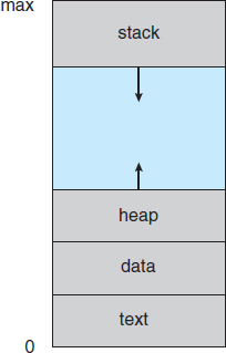
Informally, as mentioned earlier, a process is a program in execution. A process is more than the program code, which is sometimes known as the text section. It also includes the current activity, as represented by the value of the program counter and the contents of the processor's registers. A process generally also includes the process stack, which contains temporary data (such as function parameters, return addresses, and local variables), and a data section, which contains global variables. A process may also include a heap, which is memory that is dynamically allocated during process run time. The structure of a process in memory is shown in Figure 3.1.
We emphasize that a program by itself is not a process. A program is a passive entity, such as a file containing a list of instructions stored on disk (often called an executable file). In contrast, a process is an active entity, with a program counter specifying the next instruction to execute and a set of associated resources. A program becomes a process when an executable file is loaded into memory. Two common techniques for loading executable files are double-clicking an icon representing the executable file and entering the name of the executable file on the command line (as in prog.exe or a.out).
Although two processes may be associated with the same program, they are nevertheless considered two separate execution sequences. For instance, several users may be running different copies of the mail program, or the same user may invoke many copies of the web browser program. Each of these is a separate process; and although the text sections are equivalent, the data, heap, and stack sections vary. It is also common to have a process that spawns many processes as it runs. We discuss such matters in Section 3.4.
Note that a process itself can be an execution environment for other code. The Java programming environment provides a good example. In most circumstances, an executable Java program is executed within the Java virtual machine (JVM). The JVM executes as a process that interprets the loaded Java code and takes actions (via native machine instructions) on behalf of that code. For example, to run the compiled Java program Program.class, we would enter
java Program
The command java runs the JVM as an ordinary process, which in turns executes the Java program Program in the virtual machine. The concept is the same as simulation, except that the code, instead of being written for a different instruction set, is written in the Java language.
3.1.2 Process State
As a process executes, it changes state. The state of a process is defined in part by the current activity of that process. A process may be in one of the following states:
- New. The process is being created.
- Running. Instructions are being executed.
- Waiting. The process is waiting for some event to occur (such as an I/O completion or reception of a signal).
- Ready. The process is waiting to be assigned to a processor.
- Terminated. The process has finished execution.
These names are arbitrary, and they vary across operating systems. The states that they represent are found on all systems, however. Certain operating systems also more finely delineate process states. It is important to realize that only one process can be running on any processor at any instant. Many processes may be ready and waiting, however. The state diagram corresponding to these states is presented in Figure 3.2.
3.1.3 Process Control Block
Each process is represented in the operating system by a process control block (PCB)—also called a task control block. A PCB is shown in Figure 3.3. It contains many pieces of information associated with a specific process, including these:
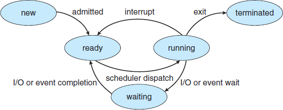
Figure 3.2 Diagram of process state.
- Process state. The state may be new, ready, running, waiting, halted, and so on.
- Program counter. The counter indicates the address of the next instruction to be executed for this process.
- CPU registers. The registers vary in number and type, depending on the computer architecture. They include accumulators, index registers, stack pointers, and general-purpose registers, plus any condition-code information. Along with the program counter, this state information must be saved when an interrupt occurs, to allow the process to be continued correctly afterward (Figure 3.4).
- CPU-scheduling information. This information includes a process priority, pointers to scheduling queues, and any other scheduling parameters. (Chapter 6 describes process scheduling.)
- Memory-management information. This information may include such items as the value of the base and limit registers and the page tables, or the segment tables, depending on the memory system used by the operating system (Chapter 8).

Figure 3.3 Process control block (PCB).
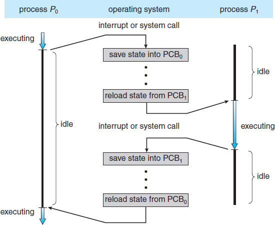
Figure 3.4 Diagram showing CPU switch from process to process.
- Accounting information. This information includes the amount of CPU and real time used, time limits, account numbers, job or process numbers, and so on.
- I/O status information. This information includes the list of I/O devices allocated to the process, a list of open files, and so on.
In brief, the PCB simply serves as the repository for any information that may vary from process to process.
3.1.4 Threads
The process model discussed so far has implied that a process is a program that performs a single thread of execution. For example, when a process is running a word-processor program, a single thread of instructions is being executed. This single thread of control allows the process to perform only one task at a time. The user cannot simultaneously type in characters and run the spell checker within the same process, for example. Most modern operating systems have extended the process concept to allow a process to have multiple threads of execution and thus to perform more than one task at a time. This feature is especially beneficial on multicore systems, where multiple threads can run in parallel. On a system that supports threads, the PCB is expanded to include information for each thread. Other changes throughout the system are also needed to support threads. Chapter 4 explores threads in detail.
PROCESS REPRESENTATION IN LINUX
The process control block in the Linux operating system is represented by the C structure task_struct, which is found in the <linux/sched.h> include file in the kernel source-code directory. This structure contains all the necessary information for representing a process, including the state of the process, scheduling and memory-management information, list of open files, and pointers to the process's parent and a list of its children and siblings. (A process's parent is the process that created it; its children are any processes that it creates. Its siblings are children with the same parent process.) Some of these fields include:
long state; /* state of the process */
struct sched_entity se; /* scheduling information */
struct task_struct *parent; /* this process's parent */
struct list_head children; /* this process's children */
struct files_struct *files; /* list of open files */
struct mm_struct *mm; /* address space of this process */
For example, the state of a process is represented by the field long state in this structure. Within the Linux kernel, all active processes are represented using a doubly linked list of task_struct. The kernel maintains a pointer—current—to the process currently executing on the system, as shown below:
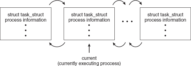
As an illustration of how the kernel might manipulate one of the fields in the task_struct for a specified process, let's assume the system would like to change the state of the process currently running to the value new_state. If current is a pointer to the process currently executing, its state is changed with the following:
current->state = new_state;
3.2 Process Scheduling
The objective of multiprogramming is to have some process running at all times, to maximize CPU utilization. The objective of time sharing is to switch the CPU among processes so frequently that users can interact with each program while it is running. To meet these objectives, the process scheduler selects an available process (possibly from a set of several available processes) for program execution on the CPU. For a single-processor system, there will never be more than one running process. If there are more processes, the rest will have to wait until the CPU is free and can be rescheduled.
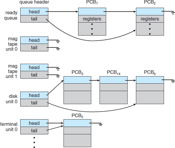
Figure 3.5 The ready queue and various I/O device queues.
3.2.1 Scheduling Queues
As processes enter the system, they are put into a job queue, which consists of all processes in the system. The processes that are residing in main memory and are ready and waiting to execute are kept on a list called the ready queue. This queue is generally stored as a linked list. A ready-queue header contains pointers to the first and final PCBs in the list. Each PCB includes a pointer field that points to the next PCB in the ready queue.
The system also includes other queues. When a process is allocated the CPU, it executes for a while and eventually quits, is interrupted, or waits for the occurrence of a particular event, such as the completion of an I/O request. Suppose the process makes an I/O request to a shared device, such as a disk. Since there are many processes in the system, the disk may be busy with the I/O request of some other process. The process therefore may have to wait for the disk. The list of processes waiting for a particular I/O device is called a device queue. Each device has its own device queue (Figure 3.5).
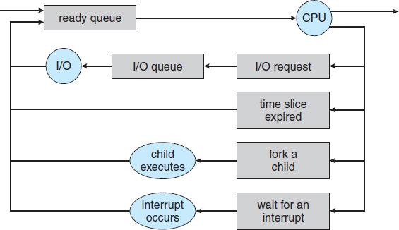
Figure 3.6 Queueing-diagram representation of process scheduling.
A common representation of process scheduling is a queueing diagram, such as that in Figure 3.6. Each rectangular box represents a queue. Two types of queues are present: the ready queue and a set of device queues. The circles represent the resources that serve the queues, and the arrows indicate the flow of processes in the system.
A new process is initially put in the ready queue. It waits there until it is selected for execution, or dispatched. Once the process is allocated the CPU and is executing, one of several events could occur:
- The process could issue an I/O request and then be placed in an I/O queue.
- The process could create a new child process and wait for the child's termination.
- The process could be removed forcibly from the CPU, as a result of an interrupt, and be put back in the ready queue.
In the first two cases, the process eventually switches from the waiting state to the ready state and is then put back in the ready queue. A process continues this cycle until it terminates, at which time it is removed from all queues and has its PCB and resources deallocated.
3.2.2 Schedulers
A process migrates among the various scheduling queues throughout its lifetime. The operating system must select, for scheduling purposes, processes from these queues in some fashion. The selection process is carried out by the appropriate scheduler.
Often, in a batch system, more processes are submitted than can be executed immediately. These processes are spooled to a mass-storage device (typically a disk), where they are kept for later execution. The long-term scheduler, or job scheduler, selects processes from this pool and loads them into memory for execution. The short-term scheduler, or CPU scheduler, selects from among the processes that are ready to execute and allocates the CPU to one of them.
The primary distinction between these two schedulers lies in frequency of execution. The short-term scheduler must select a new process for the CPU frequently. A process may execute for only a few milliseconds before waiting for an I/O request. Often, the short-term scheduler executes at least once every 100 milliseconds. Because of the short time between executions, the short-term scheduler must be fast. If it takes 10 milliseconds to decide to execute a process for 100 milliseconds, then 10/(100 + 10) = 9 percent of the CPU is being used (wasted) simply for scheduling the work.
The long-term scheduler executes much less frequently; minutes may separate the creation of one new process and the next. The long-term scheduler controls the degree of multiprogramming (the number of processes in memory). If the degree of multiprogramming is stable, then the average rate of process creation must be equal to the average departure rate of processes leaving the system. Thus, the long-term scheduler may need to be invoked only when a process leaves the system. Because of the longer interval between executions, the long-term scheduler can afford to take more time to decide which process should be selected for execution.
It is important that the long-term scheduler make a careful selection. In general, most processes can be described as either I/O bound or CPU bound. An I/O-bound process is one that spends more of its time doing I/O than it spends doing computations. A CPU-bound process, in contrast, generates I/O requests infrequently, using more of its time doing computations. It is important that the long-term scheduler select a good process mix of I/O-bound and CPU-bound processes. If all processes are I/O bound, the ready queue will almost always be empty, and the short-term scheduler will have little to do. If all processes are CPU bound, the I/O waiting queue will almost always be empty, devices will go unused, and again the system will be unbalanced. The system with the best performance will thus have a combination of CPU-bound and I/O-bound processes.
On some systems, the long-term scheduler may be absent or minimal. For example, time-sharing systems such as UNIX and Microsoft Windows systems often have no long-term scheduler but simply put every new process in memory for the short-term scheduler. The stability of these systems depends either on a physical limitation (such as the number of available terminals) or on the self-adjusting nature of human users. If performance declines to unacceptable levels on a multiuser system, some users will simply quit.
Some operating systems, such as time-sharing systems, may introduce an additional, intermediate level of scheduling. This medium-term scheduler is diagrammed in Figure 3.7. The key idea behind a medium-term scheduler is that sometimes it can be advantageous to remove a process from memory (and from active contention for the CPU) and thus reduce the degree of multiprogramming. Later, the process can be reintroduced into memory, and its execution can be continued where it left off. This scheme is called swapping. The process is swapped out, and is later swapped in, by the medium-term scheduler. Swapping may be necessary to improve the process mix or because a change in memory requirements has overcommitted available memory, requiring memory to be freed up. Swapping is discussed in Chapter 8.
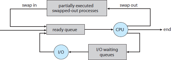
Figure 3.7 Addition of medium-term scheduling to the queueing diagram.
3.2.3 Context Switch
As mentioned in Section 1.2.1, interrupts cause the operating system to change a CPU from its current task and to run a kernel routine. Such operations happen frequently on general-purpose systems. When an interrupt occurs, the system needs to save the current context of the process running on the CPU so that it can restore that context when its processing is done, essentially suspending the process and then resuming it. The context is represented in the PCB of the process. It includes the value of the CPU registers, the process state (see Figure 3.2), and memory-management information. Generically, we perform a state save of the current state of the CPU, be it in kernel or user mode, and then a state restore to resume operations.
Switching the CPU to another process requires performing a state save of the current process and a state restore of a different process. This task is known as a context switch. When a context switch occurs, the kernel saves the context of the old process in its PCB and loads the saved context of the new process scheduled to run. Context-switch time is pure overhead, because the system does no useful work while switching. Switching speed varies from machine to machine, depending on the memory speed, the number of registers that must be copied, and the existence of special instructions (such as a single instruction to load or store all registers). A typical speed is a few milliseconds.
Context-switch times are highly dependent on hardware support. For instance, some processors (such as the Sun UltraSPARC) provide multiple sets of registers. A context switch here simply requires changing the pointer to the current register set. Of course, if there are more active processes than there are register sets, the system resorts to copying register data to and from memory, as before. Also, the more complex the operating system, the greater the amount of work that must be done during a context switch. As we will see in Chapter 8, advanced memory-management techniques may require that extra data be switched with each context. For instance, the address space of the current process must be preserved as the space of the next task is prepared for use. How the address space is preserved, and what amount of work is needed to preserve it, depend on the memory-management method of the operating system.
MULTITASKING IN MOBILE SYSTEMS
Because of the constraints imposed on mobile devices, early versions of iOS did not provide user-application multitasking; only one application runs in the foreground and all other user applications are suspended. Operating-system tasks were multitasked because they were written by Apple and well behaved. However, beginning with iOS 4, Apple now provides a limited form of multitasking for user applications, thus allowing a single foreground application to run concurrently with multiple background applications. (On a mobile device, the foreground application is the application currently open and appearing on the display. The background application remains in memory, but does not occupy the display screen.) The iOS 4 programming API provides support for multitasking, thus allowing a process to run in the background without being suspended. However, it is limited and only available for a limited number of application types, including applications
- running a single, finite-length task (such as completing a download of content from a network);
- receiving notifications of an event occurring (such as a new email message);
- with long-running background tasks (such as an audio player.)
Apple probably limits multitasking due to battery life and memory use concerns. The CPU certainly has the features to support multitasking, but Apple chooses to not take advantage of some of them in order to better manage resource use.
Android does not place such constraints on the types of applications that can run in the background. If an application requires processing while in the background, the application must use a service, a separate application component that runs on behalf of the background process. Consider a streaming audio application: if the application moves to the background, the service continues to send audio files to the audio device driver on behalf of the background application. In fact, the service will continue to run even if the background application is suspended. Services do not have a user interface and have a small memory footprint, thus providing an efficient technique for multitasking in a mobile environment.
3.3 Operations on Processes
The processes in most systems can execute concurrently, and they may be created and deleted dynamically. Thus, these systems must provide a mechanism for process creation and termination. In this section, we explore the mechanisms involved in creating processes and illustrate process creation on UNIX and Windows systems.
3.3.1 Process Creation
During the course of execution, a process may create several new processes. As mentioned earlier, the creating process is called a parent process, and the new processes are called the children of that process. Each of these new processes may in turn create other processes, forming a tree of processes.
Most operating systems (including UNIX, Linux, and Windows) identify processes according to a unique process identifier (or pid), which is typically an integer number. The pid provides a unique value for each process in the system, and it can be used as an index to access various attributes of a process within the kernel.
Figure 3.8 illustrates a typical process tree for the Linux operating system, showing the name of each process and its pid. (We use the term process rather loosely, as Linux prefers the term task instead.) The init process (which always has a pid of 1) serves as the root parent process for all user processes. Once the system has booted, the init process can also create various user processes, such as a web or print server, an ssh server, and the like. In Figure 3.8, we see two children of init—kthreadd and sshd. The kthreadd process is responsible for creating additional processes that perform tasks on behalf of the kernel (in this situation, khelper and pdflush). The sshd process is responsible for managing clients that connect to the system by using ssh (which is short for secure shell). The login process is responsible for managing clients that directly log onto the system. In this example, a client has logged on and is using the bash shell, which has been assigned pid 8416. Using the bash command-line interface, this user has created the process ps as well as the emacs editor.
On UNIX and Linux systems, we can obtain a listing of processes by using the ps command. For example, the command
ps -el
will list complete information for all processes currently active in the system. It is easy to construct a process tree similar to the one shown in Figure 3.8 by recursively tracing parent processes all the way to the init process.
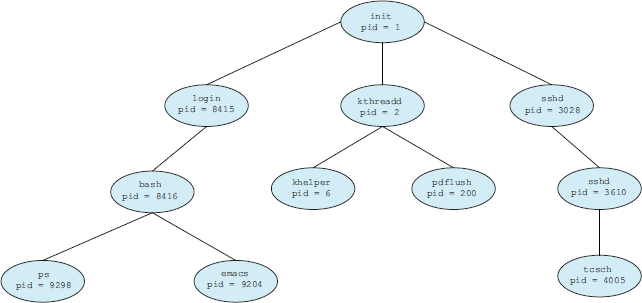
Figure 3.8 A tree of processes on a typical Linux system.
In general, when a process creates a child process, that child process will need certain resources (CPU time, memory, files, I/O devices) to accomplish its task. A child process may be able to obtain its resources directly from the operating system, or it may be constrained to a subset of the resources of the parent process. The parent may have to partition its resources among its children, or it may be able to share some resources (such as memory or files) among several of its children. Restricting a child process to a subset of the parent's resources prevents any process from overloading the system by creating too many child processes.
In addition to supplying various physical and logical resources, the parent process may pass along initialization data (input) to the child process. For example, consider a process whose function is to display the contents of a file—say, image.jpg—on the screen of a terminal. When the process is created, it will get, as an input from its parent process, the name of the file image.jpg. Using that file name, it will open the file and write the contents out. It may also get the name of the output device. Alternatively, some operating systems pass resources to child processes. On such a system, the new process may get two open files, image.jpg and the terminal device, and may simply transfer the datum between the two.
When a process creates a new process, two possibilities for execution exist:
- The parent continues to execute concurrently with its children.
- The parent waits until some or all of its children have terminated.
There are also two address-space possibilities for the new process:
- The child process is a duplicate of the parent process (it has the same program and data as the parent).
- The child process has a new program loaded into it.
To illustrate these differences, let's first consider the UNIX operating system. In UNIX, as we've seen, each process is identified by its process identifier, which is a unique integer. A new process is created by the fork() system call. The new process consists of a copy of the address space of the original process. This mechanism allows the parent process to communicate easily with its child process. Both processes (the parent and the child) continue execution at the instruction after the fork(), with one difference: the return code for the fork() is zero for the new (child) process, whereas the (nonzero) process identifier of the child is returned to the parent.
After a fork() system call, one of the two processes typically uses the exec() system call to replace the process's memory space with a new program. The exec() system call loads a binary file into memory (destroying the memory image of the program containing the exec() system call) and starts its execution. In this manner, the two processes are able to communicate and then go their separate ways. The parent can then create more children; or, if it has nothing else to do while the child runs, it can issue a wait() system call to move itself off the ready queue until the termination of the child. Because the call to exec() overlays the process's address space with a new program, the call to exec() does not return control unless an error occurs.
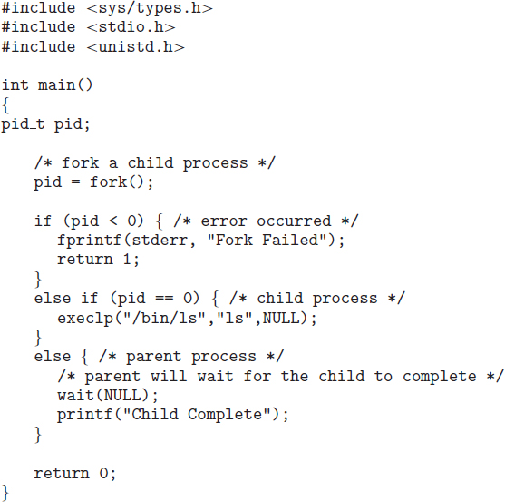
Figure 3.9 Creating a separate process using the UNIX fork() system call.
The C program shown in Figure 3.9 illustrates the UNIX system calls previously described. We now have two different processes running copies of the same program. The only difference is that the value of pid (the process identifier) for the child process is zero, while that for the parent is an integer value greater than zero (in fact, it is the actual pid of the child process). The child process inherits privileges and scheduling attributes from the parent, as well certain resources, such as open files. The child process then overlays its address space with the UNIX command /bin/ls (used to get a directory listing) using the execlp() system call (execlp() is a version of the exec() system call). The parent waits for the child process to complete with the wait() system call. When the child process completes (by either implicitly or explicitly invoking exit()), the parent process resumes from the call to wait(), where it completes using the exit() system call. This is also illustrated in Figure 3.10.
Of course, there is nothing to prevent the child from not invoking exec() and instead continuing to execute as a copy of the parent process. In this scenario, the parent and child are concurrent processes running the same code instructions. Because the child is a copy of the parent, each process has its own copy of any data.
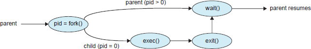
Figure 3.10 Process creation using the fork() system call.
As an alternative example, we next consider process creation in Windows. Processes are created in the Windows API using the CreateProcess() function, which is similar to fork() in that a parent creates a new child process. However, whereas fork() has the child process inheriting the address space of its parent, CreateProcess() requires loading a specified program into the address space of the child process at process creation. Furthermore, whereas fork() is passed no parameters, CreateProcess() expects no fewer than ten parameters.
The C program shown in Figure 3.11 illustrates the CreateProcess() function, which creates a child process that loads the application mspaint.exe. We opt for many of the default values of the ten parameters passed to CreateProcess(). Readers interested in pursuing the details of process creation and management in the Windows API are encouraged to consult the bibliographical notes at the end of this chapter.
The two parameters passed to the CreateProcess() function are instances of the STARTUPINFO and PROCESS_INFORMATION structures. STARTUPINFO specifies many properties of the new process, such as window size and appearance and handles to standard input and output files. The PROCESS_INFORMATION structure contains a handle and the identifiers to the newly created process and its thread. We invoke the ZeroMemory() function to allocate memory for each of these structures before proceeding with CreateProcess().
The first two parameters passed to CreateProcess() are the application name and command-line parameters. If the application name is NULL (as it is in this case), the command-line parameter specifies the application to load. In this instance, we are loading the Microsoft Windows mspaint.exe application. Beyond these two initial parameters, we use the default parameters for inheriting process and thread handles as well as specifying that there will be no creation flags. We also use the parent's existing environment block and starting directory. Last, we provide two pointers to the STARTUPINFO and PROCESS_INFORMATION structures created at the beginning of the program. In Figure 3.9, the parent process waits for the child to complete by invoking the wait() system call. The equivalent of this in Windows is WaitForSingleObject(), which is passed a handle of the child process—pi.hProcess—and waits for this process to complete. Once the child process exits, control returns from the WaitForSingleObject() function in the parent process.
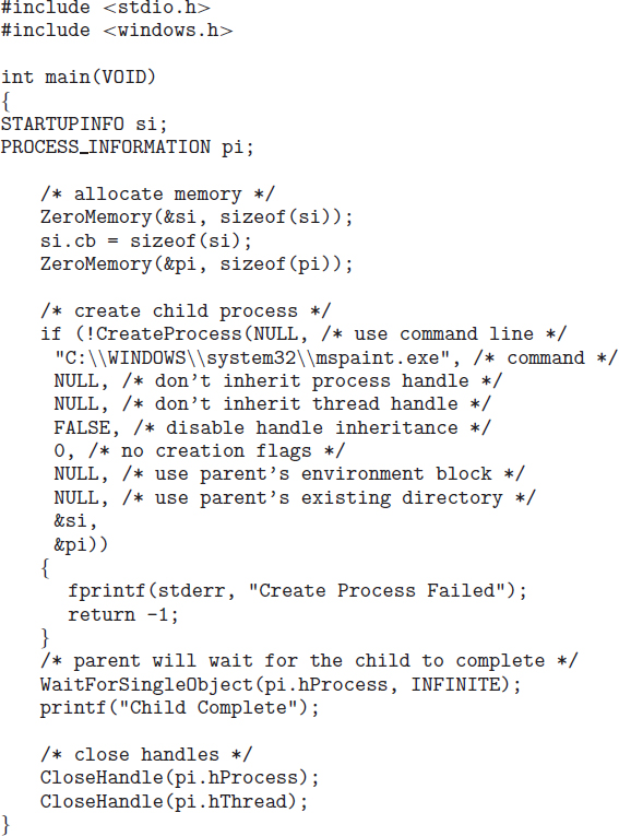
Figure 3.11 Creating a separate process using the Windows API.
3.3.2 Process Termination
A process terminates when it finishes executing its final statement and asks the operating system to delete it by using the exit() system call. At that point, the process may return a status value (typically an integer) to its parent process (via the wait() system call). All the resources of the process—including physical and virtual memory, open files, and I/O buffers—are deallocated by the operating system.
Termination can occur in other circumstances as well. A process can cause the termination of another process via an appropriate system call (for example, TerminateProcess() in Windows). Usually, such a system call can be invoked only by the parent of the process that is to be terminated. Otherwise, users could arbitrarily kill each other's jobs. Note that a parent needs to know the identities of its children if it is to terminate them. Thus, when one process creates a new process, the identity of the newly created process is passed to the parent.
A parent may terminate the execution of one of its children for a variety of reasons, such as these:
- The child has exceeded its usage of some of the resources that it has been allocated. (To determine whether this has occurred, the parent must have a mechanism to inspect the state of its children.)
- The task assigned to the child is no longer required.
- The parent is exiting, and the operating system does not allow a child to continue if its parent terminates.
Some systems do not allow a child to exist if its parent has terminated. In such systems, if a process terminates (either normally or abnormally), then all its children must also be terminated. This phenomenon, referred to as cascading termination, is normally initiated by the operating system.
To illustrate process execution and termination, consider that, in Linux and UNIX systems, we can terminate a process by using the exit() system call, providing an exit status as a parameter:
/* exit with status 1 */
exit(1);
In fact, under normal termination, exit() may be called either directly (as shown above) or indirectly (by a return statement in main()).
A parent process may wait for the termination of a child process by using the wait() system call. The wait() system call is passed a parameter that allows the parent to obtain the exit status of the child. This system call also returns the process identifier of the terminated child so that the parent can tell which of its children has terminated:
pid_t pid;
int status;

pid = wait(&status);
When a process terminates, its resources are deallocated by the operating system. However, its entry in the process table must remain there until the parent calls wait(), because the process table contains the process's exit status. A process that has terminated, but whose parent has not yet called wait(), is known as a zombie process. All processes transition to this state when they terminate, but generally they exist as zombies only briefly. Once the parent calls wait(), the process identifier of the zombie process and its entry in the process table are released.
Now consider what would happen if a parent did not invoke wait() and instead terminated, thereby leaving its child processes as orphans. Linux and UNIX address this scenario by assigning the init process as the new parent to orphan processes. (Recall from Figure 3.8 that the init process is the root of the process hierarchy in UNIX and Linux systems.) The init process periodically invokes wait(), thereby allowing the exit status of any orphaned process to be collected and releasing the orphan's process identifier and process-table entry.
3.4 Interprocess Communication
Processes executing concurrently in the operating system may be either independent processes or cooperating processes. A process is independent if it cannot affect or be affected by the other processes executing in the system. Any process that does not share data with any other process is independent. A process is cooperating if it can affect or be affected by the other processes executing in the system. Clearly, any process that shares data with other processes is a cooperating process.
There are several reasons for providing an environment that allows process cooperation:
- Information sharing. Since several users may be interested in the same piece of information (for instance, a shared file), we must provide an environment to allow concurrent access to such information.
- Computation speedup. If we want a particular task to run faster, we must break it into subtasks, each of which will be executing in parallel with the others. Notice that such a speedup can be achieved only if the computer has multiple processing cores.
- Modularity. We may want to construct the system in a modular fashion, dividing the system functions into separate processes or threads, as we discussed in Chapter 2.
- Convenience. Even an individual user may work on many tasks at the same time. For instance, a user may be editing, listening to music, and compiling in parallel.
Cooperating processes require an interprocess communication (IPC) mechanism that will allow them to exchange data and information. There are two fundamental models of interprocess communication: shared memory and message passing. In the shared-memory model, a region of memory that is shared by cooperating processes is established. Processes can then exchange information by reading and writing data to the shared region. In the message-passing model, communication takes place by means of messages exchanged between the cooperating processes. The two communications models are contrasted in Figure 3.12.
Both of the models just mentioned are common in operating systems, and many systems implement both. Message passing is useful for exchanging smaller amounts of data, because no conflicts need be avoided. Message passing is also easier to implement in a distributed system than shared memory. (Although there are systems that provide distributed shared memory, we do not consider them in this text.) Shared memory can be faster than message passing, since message-passing systems are typically implemented using system calls and thus require the more time-consuming task of kernel intervention. In shared-memory systems, system calls are required only to establish shared-memory regions. Once shared memory is established, all accesses are treated as routine memory accesses, and no assistance from the kernel is required.
MULTIPROCESS ARCHITECTURE—CHROME BROWSER
Many websites contain active content such as JavaScript, Flash, and HTML5 to provide a rich and dynamic web-browsing experience. Unfortunately, these web applications may also contain software bugs, which can result in sluggish response times and can even cause the web browser to crash. This isn't a big problem in a web browser that displays content from only one website. But most contemporary web browsers provide tabbed browsing, which allows a single instance of a web browser application to open several websites at the same time, with each site in a separate tab. To switch between the different sites, a user need only click on the appropriate tab. This arrangement is illustrated below:

A problem with this approach is that if a web application in any tab crashes, the entire process—including all other tabs displaying additional websites—crashes as well.
Google's Chrome web browser was designed to address this issue by using a multiprocess architecture. Chrome identifies three different types of processes: browser, renderers, and plug-ins.
- The browser process is responsible for managing the user interface as well as disk and network I/O. A new browser process is created when Chrome is started. Only one browser process is created.
- Renderer processes contain logic for rendering web pages. Thus, they contain the logic for handling HTML, Javascript, images, and so forth. As a general rule, a new renderer process is created for each website opened in a new tab, and so several renderer processes may be active at the same time.
- A plug-in process is created for each type of plug-in (such as Flash or QuickTime) in use. Plug-in processes contain the code for the plug-in as well as additional code that enables the plug-in to communicate with associated renderer processes and the browser process.
The advantage of the multiprocess approach is that websites run in isolation from one another. If one website crashes, only its renderer process is affected; all other processes remain unharmed. Furthermore, renderer processes run in a sandbox, which means that access to disk and network I/O is restricted, minimizing the effects of any security exploits.
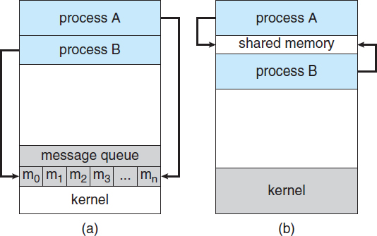
Figure 3.12 Communications models. (a) Message passing. (b) Shared memory.
Recent research on systems with several processing cores indicates that message passing provides better performance than shared memory on such systems. Shared memory suffers from cache coherency issues, which arise because shared data migrate among the several caches. As the number of processing cores on systems increases, it is possible that we will see message passing as the preferred mechanism for IPC.
In the remainder of this section, we explore shared-memory and message-passing systems in more detail.
3.4.1 Shared-Memory Systems
Interprocess communication using shared memory requires communicating processes to establish a region of shared memory. Typically, a shared-memory region resides in the address space of the process creating the shared-memory segment. Other processes that wish to communicate using this shared-memory segment must attach it to their address space. Recall that, normally, the operating system tries to prevent one process from accessing another process's memory. Shared memory requires that two or more processes agree to remove this restriction. They can then exchange information by reading and writing data in the shared areas. The form of the data and the location are determined by these processes and are not under the operating system's control. The processes are also responsible for ensuring that they are not writing to the same location simultaneously.
To illustrate the concept of cooperating processes, let's consider the producer–consumer problem, which is a common paradigm for cooperating processes. A producer process produces information that is consumed by a consumer process. For example, a compiler may produce assembly code that is consumed by an assembler. The assembler, in turn, may produce object modules that are consumed by the loader. The producer–consumer problem also provides a useful metaphor for the client–server paradigm. We generally think of a server as a producer and a client as a consumer. For example, a web server produces (that is, provides) HTML files and images, which are consumed (that is, read) by the client web browser requesting the resource.
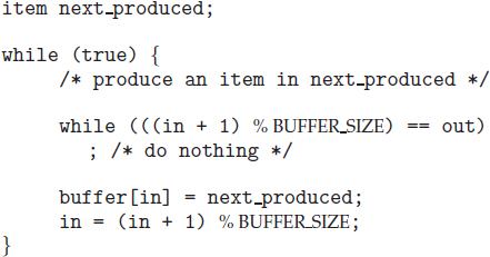
Figure 3.13 The producer process using shared memory.
One solution to the producer–consumer problem uses shared memory. To allow producer and consumer processes to run concurrently, we must have available a buffer of items that can be filled by the producer and emptied by the consumer. This buffer will reside in a region of memory that is shared by the producer and consumer processes. A producer can produce one item while the consumer is consuming another item. The producer and consumer must be synchronized, so that the consumer does not try to consume an item that has not yet been produced.
Two types of buffers can be used. The unbounded buffer places no practical limit on the size of the buffer. The consumer may have to wait for new items, but the producer can always produce new items. The bounded buffer assumes a fixed buffer size. In this case, the consumer must wait if the buffer is empty, and the producer must wait if the buffer is full.
Let's look more closely at how the bounded buffer illustrates interprocess communication using shared memory. The following variables reside in a region of memory shared by the producer and consumer processes:
#define BUFFER_SIZE 10

typedef struct {
   . . .
}item;

item buffer[BUFFER_SIZE];
int in = 0;
int out = 0;
The shared buffer is implemented as a circular array with two logical pointers: in and out. The variable in points to the next free position in the buffer; out points to the first full position in the buffer. The buffer is empty when in == out; the buffer is full when ((in + 1) % BUFFER_SIZE) == out.
The code for the producer process is shown in Figure 3.13, and the code for the consumer process is shown in Figure 3.14. The producer process has a local variable next_produced in which the new item to be produced is stored. The consumer process has a local variable next_consumed in which the item to be consumed is stored.
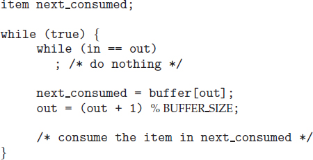
Figure 3.14 The consumer process using shared memory.
This scheme allows at most BUFFER_SIZE − 1 items in the buffer at the same time. We leave it as an exercise for you to provide a solution in which BUFFER_SIZE items can be in the buffer at the same time. In Section 3.5.1, we illustrate the POSIX API for shared memory.
One issue this illustration does not address concerns the situation in which both the producer process and the consumer process attempt to access the shared buffer concurrently. In Chapter 5, we discuss how synchronization among cooperating processes can be implemented effectively in a shared-memory environment.
3.4.2 Message-Passing Systems
In Section 3.4.1, we showed how cooperating processes can communicate in a shared-memory environment. The scheme requires that these processes share a region of memory and that the code for accessing and manipulating the shared memory be written explicitly by the application programmer. Another way to achieve the same effect is for the operating system to provide the means for cooperating processes to communicate with each other via a message-passing facility.
Message passing provides a mechanism to allow processes to communicate and to synchronize their actions without sharing the same address space. It is particularly useful in a distributed environment, where the communicating processes may reside on different computers connected by a network. For example, an Internet chat program could be designed so that chat participants communicate with one another by exchanging messages.
A message-passing facility provides at least two operations:
send(message) receive(message)
Messages sent by a process can be either fixed or variable in size. If only fixed-sized messages can be sent, the system-level implementation is straightforward. This restriction, however, makes the task of programming more difficult. Conversely, variable-sized messages require a more complex system-level implementation, but the programming task becomes simpler. This is a common kind of tradeoff seen throughout operating-system design.
If processes P and Q want to communicate, they must send messages to and receive messages from each other: a communication link must exist between them. This link can be implemented in a variety of ways. We are concerned here not with the link's physical implementation (such as shared memory, hardware bus, or network, which are covered in Chapter 17) but rather with its logical implementation. Here are several methods for logically implementing a link and the send()/receive() operations:
- Direct or indirect communication
- Synchronous or asynchronous communication
- Automatic or explicit buffering
We look at issues related to each of these features next.
3.4.2.1 Naming
Processes that want to communicate must have a way to refer to each other. They can use either direct or indirect communication.
Under direct communication, each process that wants to communicate must explicitly name the recipient or sender of the communication. In this scheme, the send() and receive() primitives are defined as:
- send(P, message)—Send a message to process P.
- receive(Q, message)—Receive a message from process Q.
A communication link in this scheme has the following properties:
- A link is established automatically between every pair of processes that want to communicate. The processes need to know only each other's identity to communicate.
- A link is associated with exactly two processes.
- Between each pair of processes, there exists exactly one link.
This scheme exhibits symmetry in addressing; that is, both the sender process and the receiver process must name the other to communicate. A variant of this scheme employs asymmetry in addressing. Here, only the sender names the recipient; the recipient is not required to name the sender. In this scheme, the send() and receive() primitives are defined as follows:
- send(P, message)—Send a message to process P.
- receive(id, message)—Receive a message from any process. The variable id is set to the name of the process with which communication has taken place.
The disadvantage in both of these schemes (symmetric and asymmetric) is the limited modularity of the resulting process definitions. Changing the identifier of a process may necessitate examining all other process definitions. All references to the old identifier must be found, so that they can be modified to the new identifier. In general, any such hard-coding techniques, where identifiers must be explicitly stated, are less desirable than techniques involving indirection, as described next.
With indirect communication, the messages are sent to and received from mailboxes, or ports. A mailbox can be viewed abstractly as an object into which messages can be placed by processes and from which messages can be removed. Each mailbox has a unique identification. For example, POSIX message queues use an integer value to identify a mailbox. A process can communicate with another process via a number of different mailboxes, but two processes can communicate only if they have a shared mailbox. The send() and receive() primitives are defined as follows:
- send(A, message)—Send a message to mailbox A.
- receive(A, message)—Receive a message from mailbox A.
In this scheme, a communication link has the following properties:
- A link is established between a pair of processes only if both members of the pair have a shared mailbox.
- A link may be associated with more than two processes.
- Between each pair of communicating processes, a number of different links may exist, with each link corresponding to one mailbox.
Now suppose that processes P1, P2, and P3 all share mailbox A. Process P1 sends a message to A, while both P2 and P3 execute a receive() from A. Which process will receive the message sent by P1? The answer depends on which of the following methods we choose:
- Allow a link to be associated with two processes at most.
- Allow at most one process at a time to execute a receive() operation.
- Allow the system to select arbitrarily which process will receive the message (that is, either P2 or P3, but not both, will receive the message). The system may define an algorithm for selecting which process will receive the message (for example, round robin, where processes take turns receiving messages). The system may identify the receiver to the sender.
A mailbox may be owned either by a process or by the operating system. If the mailbox is owned by a process (that is, the mailbox is part of the address space of the process), then we distinguish between the owner (which can only receive messages through this mailbox) and the user (which can only send messages to the mailbox). Since each mailbox has a unique owner, there can be no confusion about which process should receive a message sent to this mailbox. When a process that owns a mailbox terminates, the mailbox disappears. Any process that subsequently sends a message to this mailbox must be notified that the mailbox no longer exists.
In contrast, a mailbox that is owned by the operating system has an existence of its own. It is independent and is not attached to any particular process. The operating system then must provide a mechanism that allows a process to do the following:
- Create a new mailbox.
- Send and receive messages through the mailbox.
- Delete a mailbox.
The process that creates a new mailbox is that mailbox's owner by default. Initially, the owner is the only process that can receive messages through this mailbox. However, the ownership and receiving privilege may be passed to other processes through appropriate system calls. Of course, this provision could result in multiple receivers for each mailbox.
3.4.2.2 Synchronization
Communication between processes takes place through calls to send() and receive() primitives. There are different design options for implementing each primitive. Message passing may be either blocking or nonblocking—also known as synchronous and asynchronous. (Throughout this text, you will encounter the concepts of synchronous and asynchronous behavior in relation to various operating-system algorithms.)
- Blocking send. The sending process is blocked until the message is received by the receiving process or by the mailbox.
- Nonblocking send. The sending process sends the message and resumes operation.
- Blocking receive. The receiver blocks until a message is available.
- Nonblocking receive. The receiver retrieves either a valid message or a null.
Different combinations of send() and receive() are possible. When both send() and receive() are blocking, we have a rendezvous between the sender and the receiver. The solution to the producer–consumer problem becomes trivial when we use blocking send() and receive() statements. The producer merely invokes the blocking send() call and waits until the message is delivered to either the receiver or the mailbox. Likewise, when the consumer invokes receive(), it blocks until a message is available. This is illustrated in Figures 3.15 and 3.16.
3.4.2.3 Buffering
Whether communication is direct or indirect, messages exchanged by communicating processes reside in a temporary queue. Basically, such queues can be implemented in three ways:
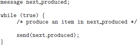
Figure 3.15 The producer process using message passing.
- Zero capacity. The queue has a maximum length of zero; thus, the link cannot have any messages waiting in it. In this case, the sender must block until the recipient receives the message.
- Bounded capacity. The queue has finite length n; thus, at most n messages can reside in it. If the queue is not full when a new message is sent, the message is placed in the queue (either the message is copied or a pointer to the message is kept), and the sender can continue execution without waiting. The link's capacity is finite, however. If the link is full, the sender must block until space is available in the queue.
- Unbounded capacity. The queue's length is potentially infinite; thus, any number of messages can wait in it. The sender never blocks.
The zero-capacity case is sometimes referred to as a message system with no buffering. The other cases are referred to as systems with automatic buffering.
3.5 Examples of IPC Systems
In this section, we explore three different IPC systems. We first cover the POSIX API for shared memory and then discuss message passing in the Mach operating system. We conclude with Windows, which interestingly uses shared memory as a mechanism for providing certain types of message passing.
3.5.1 An Example: POSIX Shared Memory
Several IPC mechanisms are available for POSIX systems, including shared memory and message passing. Here, we explore the POSIX API for shared memory.
POSIX shared memory is organized using memory-mapped files, which associate the region of shared memory with a file. A process must first create a shared-memory object using the shm_open() system call, as follows:
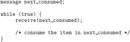
Figure 3.16 The consumer process using message passing.
shm_fd = shm_open(name, O_CREAT | O_RDRW, 0666);
The first parameter specifies the name of the shared-memory object. Processes that wish to access this shared memory must refer to the object by this name. The subsequent parameters specify that the shared-memory object is to be created if it does not yet exist (O_CREAT) and that the object is open for reading and writing (O_RDRW). The last parameter establishes the directory permissions of the shared-memory object. A successful call to shm_open() returns an integer file descriptor for the shared-memory object.
Once the object is established, the ftruncate() function is used to configure the size of the object in bytes. The call
ftruncate(shm_fd, 4096);
sets the size of the object to 4,096 bytes.
Finally, the mmap() function establishes a memory-mapped file containing the shared-memory object. It also returns a pointer to the memory-mapped file that is used for accessing the shared-memory object.
The programs shown in Figure 3.17 and 3.18 use the producer–consumer model in implementing shared memory. The producer establishes a shared-memory object and writes to shared memory, and the consumer reads from shared memory.
The producer, shown in Figure 3.17, creates a shared-memory object named OS and writes the infamous string “Hello World!” to shared memory. The program memory-maps a shared-memory object of the specified size and allows writing to the object. (Obviously, only writing is necessary for the producer.) The flag MAP_SHARED specifies that changes to the shared-memory object will be visible to all processes sharing the object. Notice that we write to the shared-memory object by calling the sprintf() function and writing the formatted string to the pointer ptr. After each write, we must increment the pointer by the number of bytes written.
The consumer process, shown in Figure 3.18, reads and outputs the contents of the shared memory. The consumer also invokes the shm_unlink() function, which removes the shared-memory segment after the consumer has accessed it. We provide further exercises using the POSIX shared-memory API in the programming exercises at the end of this chapter. Additionally, we provide more detailed coverage of memory mapping in Section 9.7.
3.5.2 An Example: Mach
As an example of message passing, we next consider the Mach operating system. You may recall that we introduced Mach in Chapter 2 as part of the Mac OS X operating system. The Mach kernel supports the creation and destruction of multiple tasks, which are similar to processes but have multiple threads of control and fewer associated resources. Most communication in Mach—including all intertask information—is carried out by messages. Messages are sent to and received from mailboxes, called ports in Mach.
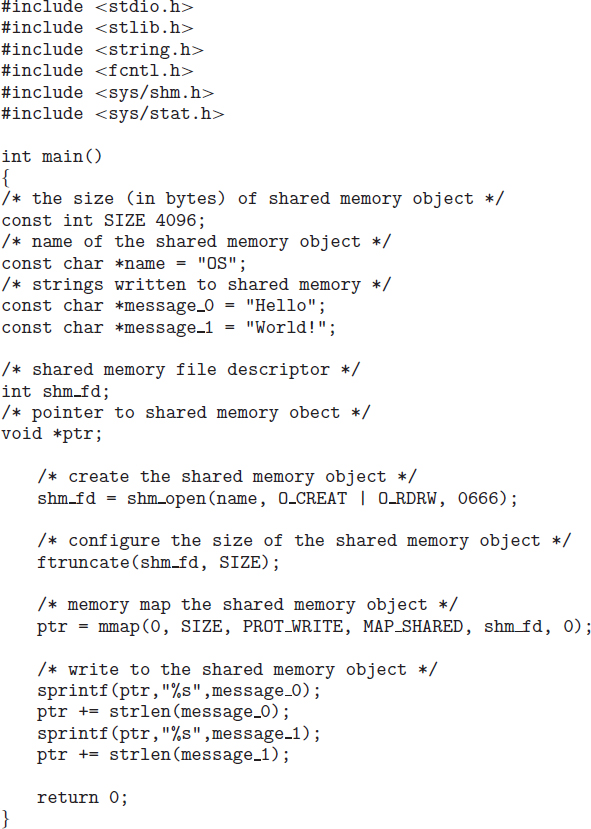
Figure 3.17 Producer process illustrating POSIX shared-memory API.
Even system calls are made by messages. When a task is created, two special mailboxes—the Kernel mailbox and the Notify mailbox—are also created. The kernel uses the Kernel mailbox to communicate with the task and sends notification of event occurrences to the Notify port. Only three system calls are needed for message transfer. The msg_send() call sends a message to a mailbox. A message is received via msg_receive(). Remote procedure calls (RPCs) are executed via msg_rpc(), which sends a message and waits for exactly one return message from the sender. In this way, the RPC models a typical subroutine procedure call but can work between systems—hence the term remote. Remote procedure calls are covered in detail in Section 3.6.2.
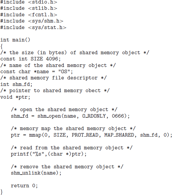
Figure 3.18 Consumer process illustrating POSIX shared-memory API.
The port_allocate() system call creates a new mailbox and allocates space for its queue of messages. The maximum size of the message queue defaults to eight messages. The task that creates the mailbox is that mailbox's owner. The owner is also allowed to receive from the mailbox. Only one task at a time can either own or receive from a mailbox, but these rights can be sent to other tasks.
The mailbox's message queue is initially empty. As messages are sent to the mailbox, the messages are copied into the mailbox. All messages have the same priority. Mach guarantees that multiple messages from the same sender are queued in first-in, first-out (FIFO) order but does not guarantee an absolute ordering. For instance, messages from two senders may be queued in any order.
The messages themselves consist of a fixed-length header followed by a variable-length data portion. The header indicates the length of the message and includes two mailbox names. One mailbox name specifies the mailbox to which the message is being sent. Commonly, the sending thread expects a reply, so the mailbox name of the sender is passed on to the receiving task, which can use it as a “return address.”
The variable part of a message is a list of typed data items. Each entry in the list has a type, size, and value. The type of the objects specified in the message is important, since objects defined by the operating system—such as ownership or receive access rights, task states, and memory segments—may be sent in messages.
The send and receive operations themselves are flexible. For instance, when a message is sent to a mailbox, the mailbox may be full. If the mailbox is not full, the message is copied to the mailbox, and the sending thread continues. If the mailbox is full, the sending thread has four options:
- Wait indefinitely until there is room in the mailbox.
- Wait at most n milliseconds.
- Do not wait at all but rather return immediately.
- Temporarily cache a message. Here, a message is given to the operating system to keep, even though the mailbox to which that message is being sent is full. When the message can be put in the mailbox, a message is sent back to the sender. Only one message to a full mailbox can be pending at any time for a given sending thread.
The final option is meant for server tasks, such as a line-printer driver. After finishing a request, such tasks may need to send a one-time reply to the task that requested service, but they must also continue with other service requests, even if the reply mailbox for a client is full.
The receive operation must specify the mailbox or mailbox set from which a message is to be received. A mailbox set is a collection of mailboxes, as declared by the task, which can be grouped together and treated as one mailbox for the purposes of the task. Threads in a task can receive only from a mailbox or mailbox set for which the task has receive access. A port_status() system call returns the number of messages in a given mailbox. The receive operation attempts to receive from (1) any mailbox in a mailbox set or (2) a specific (named) mailbox. If no message is waiting to be received, the receiving thread can either wait at most n milliseconds or not wait at all.
The Mach system was especially designed for distributed systems, which we discuss in Chapter 17, but Mach was shown to be suitable for systems with fewer processing cores, as evidenced by its inclusion in the Mac OS X system. The major problem with message systems has generally been poor performance caused by double copying of messages: the message is copied first from the sender to the mailbox and then from the mailbox to the receiver. The Mach message system attempts to avoid double-copy operations by using virtual-memory-management techniques (Chapter 9). Essentially, Mach maps the address space containing the sender's message into the receiver's address space. The message itself is never actually copied. This message-management technique provides a large performance boost but works for only intrasystem messages. The Mach operating system is discussed in more detail in the online Appendix B.
3.5.3 An Example: Windows
The Windows operating system is an example of modern design that employs modularity to increase functionality and decrease the time needed to implement new features. Windows provides support for multiple operating environments, or subsystems. Application programs communicate with these subsystems via a message-passing mechanism. Thus, application programs can be considered clients of a subsystem server.
The message-passing facility in Windows is called the advanced local procedure call (ALPC) facility. It is used for communication between two processes on the same machine. It is similar to the standard remote procedure call (RPC) mechanism that is widely used, but it is optimized for and specific to Windows. (Remote procedure calls are covered in detail in Section 3.6.2.) Like Mach, Windows uses a port object to establish and maintain a connection between two processes. Windows uses two types of ports: connection ports and communication ports.
Server processes publish connection-port objects that are visible to all processes. When a client wants services from a subsystem, it opens a handle to the server's connection-port object and sends a connection request to that port. The server then creates a channel and returns a handle to the client. The channel consists of a pair of private communication ports: one for client—server messages, the other for server—client messages. Additionally, communication channels support a callback mechanism that allows the client and server to accept requests when they would normally be expecting a reply.
When an ALPC channel is created, one of three message-passing techniques is chosen:
- For small messages (up to 256 bytes), the port's message queue is used as intermediate storage, and the messages are copied from one process to the other.
- Larger messages must be passed through a section object, which is a region of shared memory associated with the channel.
- When the amount of data is too large to fit into a section object, an API is available that allows server processes to read and write directly into the address space of a client.
The client has to decide when it sets up the channel whether it will need to send a large message. If the client determines that it does want to send large messages, it asks for a section object to be created. Similarly, if the server decides that replies will be large, it creates a section object. So that the section object can be used, a small message is sent that contains a pointer and size information about the section object. This method is more complicated than the first method listed above, but it avoids data copying. The structure of advanced local procedure calls in Windows is shown in Figure 3.19.
It is important to note that the ALPC facility in Windows is not part of the Windows API and hence is not visible to the application programmer. Rather, applications using the Windows API invoke standard remote procedure calls. When the RPC is being invoked on a process on the same system, the RPC is handled indirectly through an ALPC. procedure call. Additionally, many kernel services use ALPC to communicate with client processes.
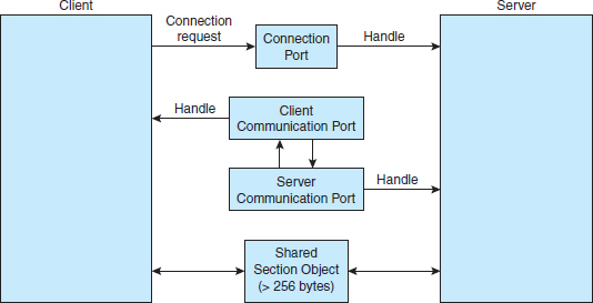
Figure 3.19 Advanced local procedure calls in Windows.
3.6 Communication in Client–Server Systems
In Section 3.4, we described how processes can communicate using shared memory and message passing. These techniques can be used for communication in client–server systems (Section 1.11.4) as well. In this section, we explore three other strategies for communication in client–server systems: sockets, remote procedure calls (RPCs), and pipes.
3.6.1 Sockets
A socket is defined as an endpoint for communication. A pair of processes communicating over a network employs a pair of sockets—one for each process. A socket is identified by an IP address concatenated with a port number. In general, sockets use a client–server architecture. The server waits for incoming client requests by listening to a specified port. Once a request is received, the server accepts a connection from the client socket to complete the connection. Servers implementing specific services (such as telnet, FTP, and HTTP) listen to well-known ports (a telnet server listens to port 23; an FTP server listens to port 21; and a web, or HTTP, server listens to port 80). All ports below 1024 are considered well known; we can use them to implement standard services.
When a client process initiates a request for a connection, it is assigned a port by its host computer. This port has some arbitrary number greater than 1024. For example, if a client on host X with IP address 146.86.5.20 wishes to establish a connection with a web server (which is listening on port 80) at address 161.25.19.8, host X may be assigned port 1625. The connection will consist of a pair of sockets: (146.86.5.20:1625) on host X and (161.25.19.8:80) on the web server. This situation is illustrated in Figure 3.20. The packets traveling between the hosts are delivered to the appropriate process based on the destination port number.
All connections must be unique. Therefore, if another process also on host X wished to establish another connection with the same web server, it would be assigned a port number greater than 1024 and not equal to 1625. This ensures that all connections consist of a unique pair of sockets.
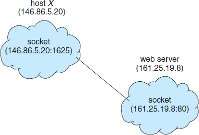
Figure 3.20 Communication using sockets.
Although most program examples in this text use C, we will illustrate sockets using Java, as it provides a much easier interface to sockets and has a rich library for networking utilities. Those interested in socket programming in C or C++ should consult the bibliographical notes at the end of the chapter.
Java provides three different types of sockets. Connection-oriented (TCP) sockets are implemented with the Socket class. Connectionless (UDP) sockets use the DatagramSocket class. Finally, the MulticastSocket class is a subclass of the DatagramSocket class. A multicast socket allows data to be sent to multiple recipients.
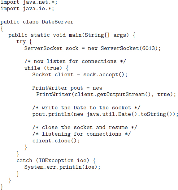
Our example describes a date server that uses connection-oriented TCP sockets. The operation allows clients to request the current date and time from the server. The server listens to port 6013, although the port could have any arbitrary number greater than 1024. When a connection is received, the server returns the date and time to the client.
The date server is shown in Figure 3.21. The server creates a ServerSocket that specifies that it will listen to port 6013. The server then begins listening to the port with the accept() method. The server blocks on the accept() method waiting for a client to request a connection. When a connection request is received, accept() returns a socket that the server can use to communicate with the client.
The details of how the server communicates with the socket are as follows. The server first establishes a PrintWriter object that it will use to communicate with the client. A PrintWriter object allows the server to write to the socket using the routine print() and println() methods for output. The server process sends the date to the client, calling the method println(). Once it has written the date to the socket, the server closes the socket to the client and resumes listening for more requests.
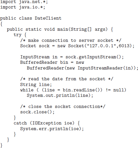
A client communicates with the server by creating a socket and connecting to the port on which the server is listening. We implement such a client in the Java program shown in Figure 3.22. The client creates a Socket and requests a connection with the server at IP address 127.0.0.1 on port 6013. Once the connection is made, the client can read from the socket using normal stream I/O statements. After it has received the date from the server, the client closes the socket and exits. The IP address 127.0.0.1 is a special IP address known as the loopback. When a computer refers to IP address 127.0.0.1, it is referring to itself. This mechanism allows a client and server on the same host to communicate using the TCP/IP protocol. The IP address 127.0.0.1 could be replaced with the IP address of another host running the date server. In addition to an IP address, an actual host name, such as www.westminstercollege.edu, can be used as well.
Communication using sockets—although common and efficient—is considered a low-level form of communication between distributed processes. One reason is that sockets allow only an unstructured stream of bytes to be exchanged between the communicating threads. It is the responsibility of the client or server application to impose a structure on the data. In the next two subsections, we look at two higher-level methods of communication: remote procedure calls (RPCs) and pipes.
3.6.2 Remote Procedure Calls
One of the most common forms of remote service is the RPC paradigm, which we discussed briefly in Section 3.5.2. The RPC was designed as a way to abstract the procedure-call mechanism for use between systems with network connections. It is similar in many respects to the IPC mechanism described in Section 3.4, and it is usually built on top of such a system. Here, however, because we are dealing with an environment in which the processes are executing on separate systems, we must use a message-based communication scheme to provide remote service.
In contrast to IPC messages, the messages exchanged in RPC communication are well structured and are thus no longer just packets of data. Each message is addressed to an RPC daemon listening to a port on the remote system, and each contains an identifier specifying the function to execute and the parameters to pass to that function. The function is then executed as requested, and any output is sent back to the requester in a separate message.
A port is simply a number included at the start of a message packet. Whereas a system normally has one network address, it can have many ports within that address to differentiate the many network services it supports. If a remote process needs a service, it addresses a message to the proper port. For instance, if a system wished to allow other systems to be able to list its current users, it would have a daemon supporting such an RPC attached to a port—say, port 3027. Any remote system could obtain the needed information (that is, the list of current users) by sending an RPC message to port 3027 on the server. The data would be received in a reply message.
The semantics of RPCs allows a client to invoke a procedure on a remote host as it would invoke a procedure locally. The RPC system hides the details that allow communication to take place by providing a stub on the client side. Typically, a separate stub exists for each separate remote procedure. When the client invokes a remote procedure, the RPC system calls the appropriate stub, passing it the parameters provided to the remote procedure. This stub locates the port on the server and marshals the parameters. Parameter marshalling involves packaging the parameters into a form that can be transmitted over a network. The stub then transmits a message to the server using message passing. A similar stub on the server side receives this message and invokes the procedure on the server. If necessary, return values are passed back to the client using the same technique. On Windows systems, stub code is compiled from a specification written in the Microsoft Interface Definition Language (MIDL), which is used for defining the interfaces between client and server programs.
One issue that must be dealt with concerns differences in data representation on the client and server machines. Consider the representation of 32-bit integers. Some systems (known as big-endian) store the most significant byte first, while other systems (known as little-endian) store the least significant byte first. Neither order is “better” per se; rather, the choice is arbitrary within a computer architecture. To resolve differences like this, many RPC systems define a machine-independent representation of data. One such representation is known as external data representation (XDR). On the client side, parameter marshalling involves converting the machine-dependent data into XDR before they are sent to the server. On the server side, the XDR data are unmarshalled and converted to the machine-dependent representation for the server.
Another important issue involves the semantics of a call. Whereas local procedure calls fail only under extreme circumstances, RPCs can fail, or be duplicated and executed more than once, as a result of common network errors. One way to address this problem is for the operating system to ensure that messages are acted on exactly once, rather than at most once. Most local procedure calls have the “exactly once” functionality, but it is more difficult to implement.
First, consider “at most once.” This semantic can be implemented by attaching a timestamp to each message. The server must keep a history of all the timestamps of messages it has already processed or a history large enough to ensure that repeated messages are detected. Incoming messages that have a timestamp already in the history are ignored. The client can then send a message one or more times and be assured that it only executes once.
For “exactly once,” we need to remove the risk that the server will never receive the request. To accomplish this, the server must implement the “at most once” protocol described above but must also acknowledge to the client that the RPC call was received and executed. These ACK messages are common throughout networking. The client must resend each RPC call periodically until it receives the ACK for that call.
Yet another important issue concerns the communication between a server and a client. With standard procedure calls, some form of binding takes place during link, load, or execution time (Chapter 8) so that a procedure call's name is replaced by the memory address of the procedure call. The RPC scheme requires a similar binding of the client and the server port, but how does a client know the port numbers on the server? Neither system has full information about the other, because they do not share memory.
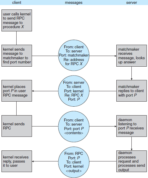
Figure 3.23 Execution of a remote procedure call (RPC).
Two approaches are common. First, the binding information may be predetermined, in the form of fixed port addresses. At compile time, an RPC call has a fixed port number associated with it. Once a program is compiled, the server cannot change the port number of the requested service. Second, binding can be done dynamically by a rendezvous mechanism. Typically, an operating system provides a rendezvous (also called a matchmaker) daemon on a fixed RPC port. A client then sends a message containing the name of the RPC to the rendezvous daemon requesting the port address of the RPC it needs to execute. The port number is returned, and the RPC calls can be sent to that port until the process terminates (or the server crashes). This method requires the extra overhead of the initial request but is more flexible than the first approach. Figure 3.23 shows a sample interaction.
The RPC scheme is useful in implementing a distributed file system (Chapter 17). Such a system can be implemented as a set of RPC daemons and clients. The messages are addressed to the distributed file system port on a server on which a file operation is to take place. The message contains the disk operation to be performed. The disk operation might be read, write, rename, delete, or status, corresponding to the usual file-related system calls. The return message contains any data resulting from that call, which is executed by the DFS daemon on behalf of the client. For instance, a message might contain a request to transfer a whole file to a client or be limited to a simple block request. In the latter case, several requests may be needed if a whole file is to be transferred.
3.6.3 Pipes
A pipe acts as a conduit allowing two processes to communicate. Pipes were one of the first IPC mechanisms in early UNIX systems. They typically provide one of the simpler ways for processes to communicate with one another, although they also have some limitations. In implementing a pipe, four issues must be considered:
- Does the pipe allow bidirectional communication, or is communication unidirectional?
- If two-way communication is allowed, is it half duplex (data can travel only one way at a time) or full duplex (data can travel in both directions at the same time)?
- Must a relationship (such as parent–child) exist between the communicating processes?
- Can the pipes communicate over a network, or must the communicating processes reside on the same machine?
In the following sections, we explore two common types of pipes used on both UNIX and Windows systems: ordinary pipes and named pipes.
3.6.3.1 Ordinary Pipes
Ordinary pipes allow two processes to communicate in standard producer–consumer fashion: the producer writes to one end of the pipe (the write-end) and the consumer reads from the other end (the read-end). As a result, ordinary pipes are unidirectional, allowing only one-way communication. If two-way communication is required, two pipes must be used, with each pipe sending data in a different direction. We next illustrate constructing ordinary pipes on both UNIX and Windows systems. In both program examples, one process writes the message Greetings to the pipe, while the other process reads this message from the pipe.
On UNIX systems, ordinary pipes are constructed using the function
pipe(int fd[])
This function creates a pipe that is accessed through the int fd[] file descriptors: fd[0] is the read-end of the pipe, and fd[1] is the write-end. UNIX treats a pipe as a special type of file. Thus, pipes can be accessed using ordinary read() and write() system calls.
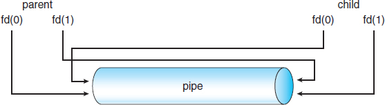
Figure 3.24 File descriptors for an ordinary pipe.
An ordinary pipe cannot be accessed from outside the process that created it. Typically, a parent process creates a pipe and uses it to communicate with a child process that it creates via fork(). Recall from Section 3.3.1 that a child process inherits open files from its parent. Since a pipe is a special type of file, the child inherits the pipe from its parent process. Figure 3.24 illustrates the relationship of the file descriptor fd to the parent and child processes.
In the UNIX program shown in Figure 3.25, the parent process creates a pipe and then sends a fork() call creating the child process. What occurs after the fork() call depends on how the data are to flow through the pipe. In this instance, the parent writes to the pipe, and the child reads from it. It is important to notice that both the parent process and the child process initially close their unused ends of the pipe. Although the program shown in Figure 3.25 does not require this action, it is an important step to ensure that a process reading from the pipe can detect end-of-file (read() returns 0) when the writer has closed its end of the pipe.
Ordinary pipes on Windows systems are termed anonymous pipes, and they behave similarly to their UNIX counterparts: they are unidirectional and employ parent–child relationships between the communicating processes. In addition, reading and writing to the pipe can be accomplished with the ordinary ReadFile() and WriteFile() functions. The Windows API for creating pipes is the CreatePipe() function, which is passed four parameters. The parameters provide separate handles for (1) reading and (2) writing to the pipe, as well as (3) an instance of the STARTUPINFO structure, which is used to specify that the child process is to inherit the handles of the pipe. Furthermore, (4) the size of the pipe (in bytes) may be specified.
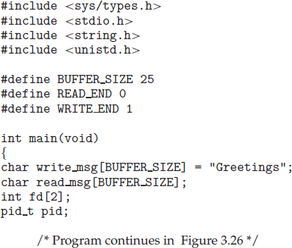
Figure 3.25 Ordinary pipe in UNIX.
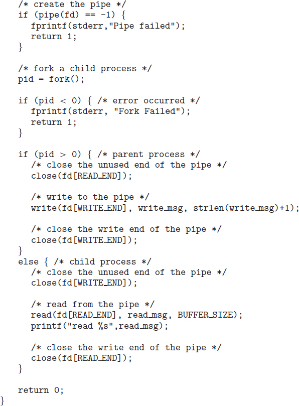
Figure 3.26 Figure 3.25, continued.
Figure 3.27 illustrates a parent process creating an anonymous pipe for communicating with its child. Unlike UNIX systems, in which a child process automatically inherits a pipe created by its parent, Windows requires the programmer to specify which attributes the child process will inherit. This is accomplished by first initializing the SECURITY_ATTRIBUTES structure to allow handles to be inherited and then redirecting the child process's handles for standard input or standard output to the read or write handle of the pipe. Since the child will be reading from the pipe, the parent must redirect the child's standard input to the read handle of the pipe. Furthermore, as the pipes are half duplex, it is necessary to prohibit the child from inheriting the write-end of the pipe. The program to create the child process is similar to the program in Figure 3.11, except that the fifth parameter is set to TRUE, indicating that the child process is to inherit designated handles from its parent. Before writing to the pipe, the parent first closes its unused read end of the pipe. The child process that reads from the pipe is shown in Figure 3.29. Before reading from the pipe, this program obtains the read handle to the pipe by invoking GetStdHandle().
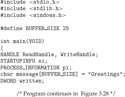
Figure 3.27 Windows anonymous pipe—parent process.
Note that ordinary pipes require a parent–child relationship between the communicating processes on both UNIX and Windows systems. This means that these pipes can be used only for communication between processes on the same machine.
3.6.3.2 Named Pipes
Ordinary pipes provide a simple mechanism for allowing a pair of processes to communicate. However, ordinary pipes exist only while the processes are communicating with one another. On both UNIX and Windows systems, once the processes have finished communicating and have terminated, the ordinary pipe ceases to exist.
Named pipes provide a much more powerful communication tool. Communication can be bidirectional, and no parent–child relationship is required. Once a named pipe is established, several processes can use it for communication. In fact, in a typical scenario, a named pipe has several writers. Additionally, named pipes continue to exist after communicating processes have finished. Both UNIX and Windows systems support named pipes, although the details of implementation differ greatly. Next, we explore named pipes in each of these systems.
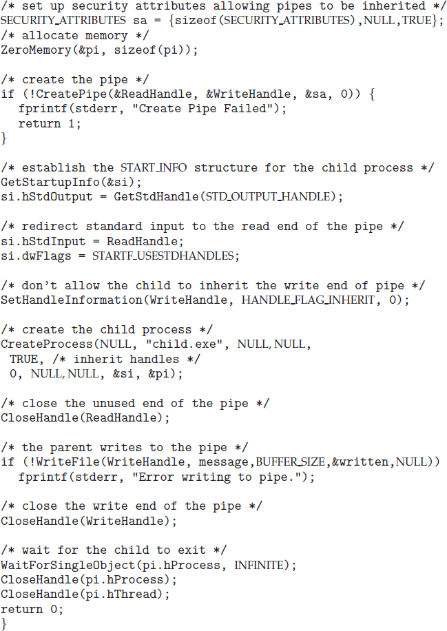
Figure 3.28 Figure 3.27, continued.
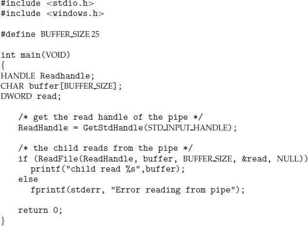
Figure 3.29 Windows anonymous pipes—child process.
Named pipes are referred to as FIFOs in UNIX systems. Once created, they appear as typical files in the file system. A FIFO is created with the mkfifo() system call and manipulated with the ordinary open(), read(), write(), and close() system calls. It will continue to exist until it is explicitly deleted from the file system. Although FIFOs allow bidirectional communication, only half-duplex transmission is permitted. If data must travel in both directions, two FIFOs are typically used. Additionally, the communicating processes must reside on the same machine. If intermachine communication is required, sockets (Section 3.6.1) must be used.
Named pipes on Windows systems provide a richer communication mechanism than their UNIX counterparts. Full-duplex communication is allowed, and the communicating processes may reside on either the same or different machines. Additionally, only byte-oriented data may be transmitted across a UNIX FIFO, whereas Windows systems allow either byte- or message-oriented data. Named pipes are created with the CreateNamedPipe() function, and a client can connect to a named pipe using ConnectNamedPipe(). Communication over the named pipe can be accomplished using the ReadFile() and WriteFile() functions.
3.7 Summary
A process is a program in execution. As a process executes, it changes state. The state of a process is defined by that process's current activity. Each process may be in one of the following states: new, ready, running, waiting, or terminated.
Pipes are used quite often in the UNIX command-line environment for situations in which the output of one command serves as input to another. For example, the UNIX ls command produces a directory listing. For especially long directory listings, the output may scroll through several screens. The command more manages output by displaying only one screen of output at a time; the user must press the space bar to move from one screen to the next. Setting up a pipe between the ls and more commands (which are running as individual processes) allows the output of ls to be delivered as the input to more, enabling the user to display a large directory listing a screen at a time. A pipe can be constructed on the command line using the | character. The complete command is
ls | more
In this scenario, the ls command serves as the producer, and its output is consumed by the more command.
Windows systems provide a more command for the DOS shell with functionality similar to that of its UNIX counterpart. The DOS shell also uses the | character for establishing a pipe. The only difference is that to get a directory listing, DOS uses the dir command rather than ls, as shown below:
dir | more
Each process is represented in the operating system by its own process control block (PCB).
A process, when it is not executing, is placed in some waiting queue. There are two major classes of queues in an operating system: I/O request queues and the ready queue. The ready queue contains all the processes that are ready to execute and are waiting for the CPU. Each process is represented by a PCB.
The operating system must select processes from various scheduling queues. Long-term (job) scheduling is the selection of processes that will be allowed to contend for the CPU. Normally, long-term scheduling is heavily influenced by resource-allocation considerations, especially memory management. Short-term (CPU) scheduling is the selection of one process from the ready queue.
Operating systems must provide a mechanism for parent processes to create new child processes. The parent may wait for its children to terminate before proceeding, or the parent and children may execute concurrently. There are several reasons for allowing concurrent execution: information sharing, computation speedup, modularity, and convenience.
The processes executing in the operating system may be either independent processes or cooperating processes. Cooperating processes require an interprocess communication mechanism to communicate with each other. Principally, communication is achieved through two schemes: shared memory and message passing. The shared-memory method requires communicating processes to share some variables. The processes are expected to exchange information through the use of these shared variables. In a shared-memory system, the responsibility for providing communication rests with the application programmers; the operating system needs to provide only the shared memory. The message-passing method allows the processes to exchange messages. The responsibility for providing communication may rest with the operating system itself. These two schemes are not mutually exclusive and can be used simultaneously within a single operating system.
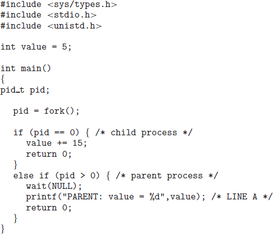
Figure 3.30 What output will be at Line A?
Communication in client–server systems may use (1) sockets, (2) remote procedure calls (RPCs), or (3) pipes. A socket is defined as an endpoint for communication. A connection between a pair of applications consists of a pair of sockets, one at each end of the communication channel. RPCs are another form of distributed communication. An RPC occurs when a process (or thread) calls a procedure on a remote application. Pipes provide a relatively simple ways for processes to communicate with one another. Ordinary pipes allow communication between parent and child processes, while named pipes permit unrelated processes to communicate.
Practice Exercises
3.1 Using the program shown in Figure 3.30, explain what the output will be at LINE A.
3.2 Including the initial parent process, how many processes are created by the program shown in Figure 3.31?
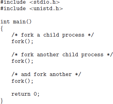
Figure 3.31 How many processes are created?
3.3 Original versions of Apple's mobile iOS operating system provided no means of concurrent processing. Discuss three major complications that concurrent processing adds to an operating system.
3.4 The Sun UltraSPARC processor has multiple register sets. Describe what happens when a context switch occurs if the new context is already loaded into one of the register sets. What happens if the new context is in memory rather than in a register set and all the register sets are in use?
3.5 When a process creates a new process using the fork() operation, which of the following states is shared between the parent process and the child process?
- Stack
- Heap
- Shared memory segments
3.6 Consider the “exactly once” semantic with respect to the RPC mechanism. Does the algorithm for implementing this semantic execute correctly even if the ACK message sent back to the client is lost due to a network problem? Describe the sequence of messages, and discuss whether “exactly once” is still preserved.
3.7 Assume that a distributed system is susceptible to server failure. What mechanisms would be required to guarantee the “exactly once” semantic for execution of RPCs?
Exercises
3.8 Describe the differences among short-term, medium-term, and long-term scheduling.
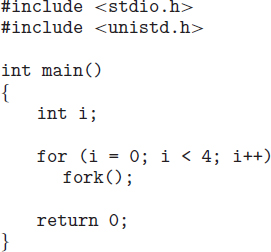
Figure 3.32 How many processes are created?
3.9 Describe the actions taken by a kernel to context-switch between processes.
3.10 Construct a process tree similar to Figure 3.8. To obtain process information for the UNIX or Linux system, use the command ps −ael.
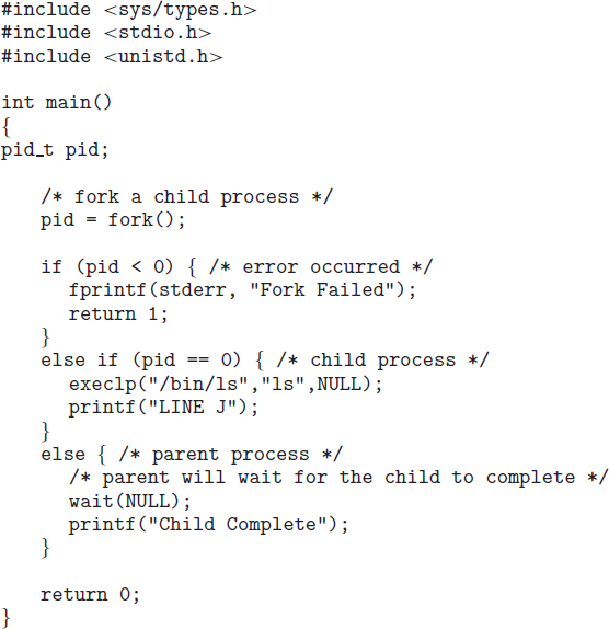
Figure 3.33 When will LINE J be reached?
Use the command man ps to get more information about the ps command. The task manager on Windows systems does not provide the parent process ID, but the process monitor tool, available from technet.microsoft.com, provides a process-tree tool.
3.11 Explain the role of the init process on UNIX and Linux systems in regard to process termination.
3.12 Including the initial parent process, how many processes are created by the program shown in Figure 3.32?
3.13 Explain the circumstances under which which the line of code marked printf(“LINE J”) in Figure 3.33 will be reached.
3.14 Using the program in Figure 3.34, identify the values of pid at lines A, B, C, and D. (Assume that the actual pids of the parent and child are 2600 and 2603, respectively.)
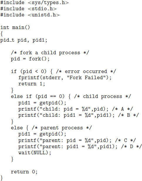
Figure 3.34 What are the pid values?
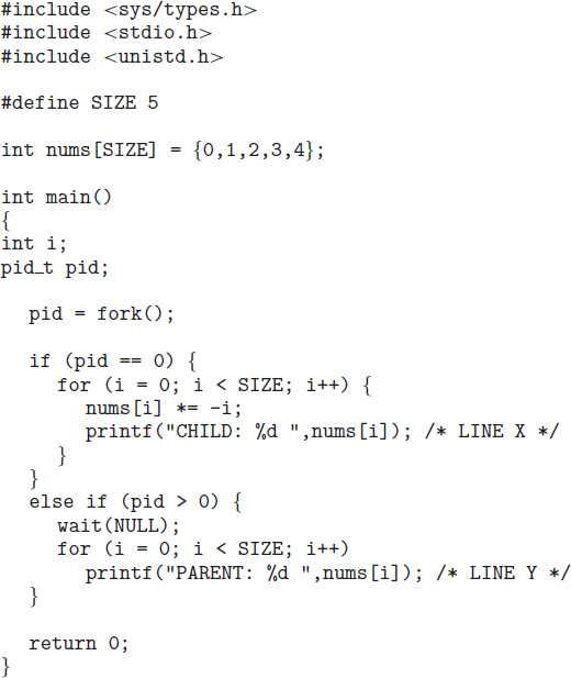
Figure 3.35 What output will be at Line X and Line Y?
3.15 Give an example of a situation in which ordinary pipes are more suitable than named pipes and an example of a situation in which named pipes are more suitable than ordinary pipes.
3.16 Consider the RPC mechanism. Describe the undesirable consequences that could arise from not enforcing either the “at most once” or “exactly once” semantic. Describe possible uses for a mechanism that has neither of these guarantees.
3.17 Using the program shown in Figure 3.35, explain what the output will be at lines X and Y.
3.18 What are the benefits and the disadvantages of each of the following? Consider both the system level and the programmer level.
- Synchronous and asynchronous communication
- Automatic and explicit buffering
- Send by copy and send by reference
- Fixed-sized and variable-sized messages
Programming Problems
3.19 Using either a UNIX or a Linux system, write a C program that forks a child process that ultimately becomes a zombie process. This zombie process must remain in the system for at least 10 seconds. Process states can be obtained from the command
ps −l
The process states are shown below the S column; processes with a state of Z are zombies. The process identifier (pid) of the child process is listed in the PID column, and that of the parent is listed in the PPID column.
Perhaps the easiest way to determine that the child process is indeed a zombie is to run the program that you have written in the background (using the &) and then run the command ps −l to determine whether the child is a zombie process. Because you do not want too many zombie processes existing in the system, you will need to remove the one that you have created. The easiest way to do that is to terminate the parent process using the kill command. For example, if the process id of the parent is 4884, you would enter
kill −9 4884
3.20 An operating system's pid manager is responsible for managing process identifiers. When a process is first created, it is assigned a unique pid by the pid manager. The pid is returned to the pid manager when the process completes execution, and the manager may later reassign this pid. Process identifiers are discussed more fully in Section 3.3.1. What is most important here is to recognize that process identifiers must be unique; no two active processes can have the same pid.
Use the following constants to identify the range of possible pid values:
#define MIN_PID 300
#define MAX_PID 5000
You may use any data structure of your choice to represent the availability of process identifiers. One strategy is to adopt what Linux has done and use a bitmap in which a value of 0 at position i indicates that a process id of value i is available and a value of 1 indicates that the process id is currently in use.
Implement the following API for obtaining and releasing a pid:
- int allocate_map(void)—Creates and initializes a data structure for representing pids; returns—1 if unsuccessful, 1 if successful
- int allocate_pid(void)—Allocates and returns a pid; returns—1 if unable to allocate a pid (all pids are in use)
- void release_pid(int pid)—Releases a pid
This programming problem will be modified later on in Chpaters 4 and 5.
3.21 The Collatz conjecture concerns what happens when we take any positive integer n and apply the following algorithm:
![]()
The conjecture states that when this algorithm is continually applied, all positive integers will eventually reach 1. For example, if n = 35, the sequence is
35, 106, 53, 160, 80, 40, 20, 10, 5, 16, 8, 4, 2, 1
Write a C program using the fork() system call that generates this sequence in the child process. The starting number will be provided from the command line. For example, if 8 is passed as a parameter on the command line, the child process will output 8, 4, 2, 1. Because the parent and child processes have their own copies of the data, it will be necessary for the child to output the sequence. Have the parent invoke the wait() call to wait for the child process to complete before exiting the program. Perform necessary error checking to ensure that a positive integer is passed on the command line.
3.22 In Exercise 3.21, the child process must output the sequence of numbers generated from the algorithm specified by the Collatz conjecture because the parent and child have their own copies of the data. Another approach to designing this program is to establish a shared-memory object between the parent and child processes. This technique allows the child to write the contents of the sequence to the shared-memory object. The parent can then output the sequence when the child completes. Because the memory is shared, any changes the child makes will be reflected in the parent process as well.
This program will be structured using POSIX shared memory as described in Section 3.5.1. The parent process will progress through the following steps:
- Establish the shared-memory object (shm_open(), ftruncate(), and mmap()).
- Create the child process and wait for it to terminate.
- Output the contents of shared memory.
- Remove the shared-memory object.
One area of concern with cooperating processes involves synchronization issues. In this exercise, the parent and child processes must be coordinated so that the parent does not output the sequence until the child finishes execution. These two processes will be synchronized using the wait() system call: the parent process will invoke wait(), which will suspend it until the child process exits.
3.23 Section 3.6.1 describes port numbers below 1024 as being well known—that is, they provide standard services. Port 17 is known as the quote-of-the-day service. When a client connects to port 17 on a server, the server responds with a quote for that day.
Modify the date server shown in Figure 3.21 so that it delivers a quote of the day rather than the current date. The quotes should be printable ASCII characters and should contain fewer than 512 characters, although multiple lines are allowed. Since port 17 is well known and therefore unavailable, have your server listen to port 6017. The date client shown in Figure 3.22 can be used to read the quotes returned by your server.
3.24 A haiku is a three-line poem in which the first line contains five syllables, the second line contains seven syllables, and the third line contains five syllables. Write a haiku server that listens to port 5575. When a client connects to this port, the server responds with a haiku. The date client shown in Figure 3.22 can be used to read the quotes returned by your haiku server.
3.25 An echo server echoes back whatever it receives from a client. For example, if a client sends the server the string Hello there!, the server will respond with Hello there!
Write an echo server using the Java networking API described in Section 3.6.1. This server will wait for a client connection using the accept() method. When a client connection is received, the server will loop, performing the following steps:
- Read data from the socket into a buffer.
- Write the contents of the buffer back to the client.
The server will break out of the loop only when it has determined that the client has closed the connection.
The date server shown in Figure 3.21 uses the java.io.BufferedReader class. BufferedReader extends the java.io.Reader class, which is used for reading character streams. However, the echo server cannot guarantee that it will read characters from clients; it may receive binary data as well. The class java.io.InputStream deals with data at the byte level rather than the character level. Thus, your echo server must use an object that extends java.io.InputStream. The read() method in the java.io.InputStream class returns −1 when the client has closed its end of the socket connection.
3.26 Design a program using ordinary pipes in which one process sends a string message to a second process, and the second process reverses the case of each character in the message and sends it back to the first process. For example, if the first process sends the message Hi There, the second process will return hI tHERE. This will require using two pipes, one for sending the original message from the first to the second process and the other for sending the modified message from the second to the first process. You can write this program using either UNIX or Windows pipes.
3.27 Design a file-copying program named filecopy using ordinary pipes. This program will be passed two parameters: the name of the file to be copied and the name of the copied file. The program will then create an ordinary pipe and write the contents of the file to be copied to the pipe. The child process will read this file from the pipe and write it to the destination file. For example, if we invoke the program as follows:
filecopy input.txt copy.txt
the file input.txt will be written to the pipe. The child process will read the contents of this file and write it to the destination file copy.txt. You may write this program using either UNIX or Windows pipes.
Programming Projects
Project 1—UNIX Shell and History Feature
This project consists of designing a C program to serve as a shell interface that accepts user commands and then executes each command in a separate process. This project can be completed on any Linux, UNIX, or Mac OS X system.
A shell interface gives the user a prompt, after which the next command is entered. The example below illustrates the prompt osh> and the user's next command: cat prog.c. (This command displays the file prog.c on the terminal using the UNIX cat command.)
osh> cat prog.c
One technique for implementing a shell interface is to have the parent process first read what the user enters on the command line (in this case, cat prog.c), and then create a separate child process that performs the command. Unless otherwise specified, the parent process waits for the child to exit before continuing. This is similar in functionality to the new process creation illustrated in Figure 3.10. However, UNIX shells typically also allow the child process to run in the background, or concurrently. To accomplish this, we add an ampersand (&) at the end of the command. Thus, if we rewrite the above command as
osh> cat prog.c &
the parent and child processes will run concurrently.
The separate child process is created using the fork() system call, and the user's command is executed using one of the system calls in the exec() family (as described in Section 3.3.1).
A C program that provides the general operations of a command-line shell is supplied in Figure 3.36. The main() function presents the prompt osh-> and outlines the steps to be taken after input from the user has been read. The main() function continually loops as long as should_run equals 1; when the user enters exit at the prompt, your program will set should_run to 0 and terminate.
This project is organized into two parts: (1) creating the child process and executing the command in the child, and (2) modifying the shell to allow a history feature.
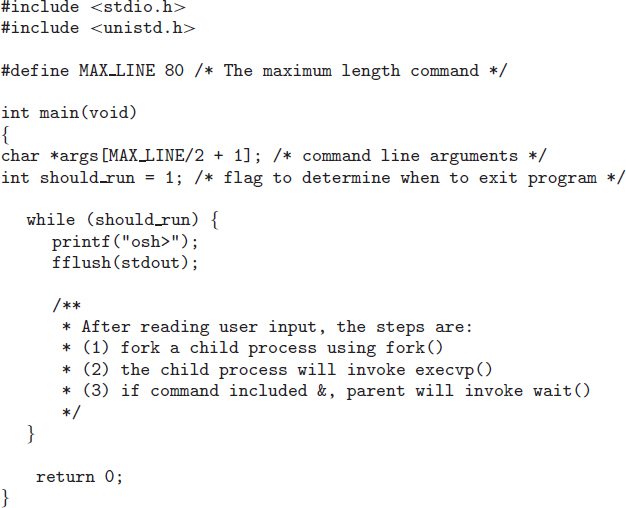
Figure 3.36 Outline of simple shell.
Part I—Creating a Child Process
The first task is to modify the main() function in Figure 3.36 so that a child process is forked and executes the command specified by the user. This will require parsing what the user has entered into separate tokens and storing the tokens in an array of character strings (args in Figure 3.36). For example, if the user enters the command ps -ael at the osh> prompt, the values stored in the args array are:
args[0] = “ps”
args[1] = “-ael”
args[2] = NULL
This args array will be passed to the execvp() function, which has the following prototype:
execvp(char *command, char *params[]);
Here, command represents the command to be performed and params stores the parameters to this command. For this project, the execvp() function should be invoked as execvp(args[0], args). Be sure to check whether the user included an & to determine whether or not the parent process is to wait for the child to exit.
Part II—Creating a History Feature
The next task is to modify the shell interface program so that it provides a history feature that allows the user to access the most recently entered commands. The user will be able to access up to 10 commands by using the feature. The commands will be consecutively numbered starting at 1, and the numbering will continue past 10. For example, if the user has entered 35 commands, the 10 most recent commands will be numbered 26 to 35.
The user will be able to list the command history by entering the command
history
at the osh> prompt. As an example, assume that the history consists of the commands (from most to least recent):
ps, ls -l, top, cal, who, date
The command history will output:
  6 ps
  5 ls -l
  4 top
  3 cal
  2 who
  1 date
Your program should support two techniques for retrieving commands from the command history:
- When the user enters !!, the most recent command in the history is executed.
- When the user enters a single ! followed by an integer N, the Nth command in the history is executed.
Continuing our example from above, if the user enters !!, the ps command will be performed; if the user enters !3, the command cal will be executed. Any command executed in this fashion should be echoed on the user's screen. The command should also be placed in the history buffer as the next command.
The program should also manage basic error handling. If there are no commands in the history, entering !! should result in a message “No commands in history.” If there is no command corresponding to the number entered with the single !, the program should output “No such command in history.”
Project 2—Linux Kernel Module for Listing Tasks
In this project, you will write a kernel module that lists all current tasks in a Linux system. Be sure to review the programming project in Chapter 2, which deals with creating Linux kernel modules, before you begin this project. The project can be completed using the Linux virtual machine provided with this text.
Part I—Iterating over Tasks Linearly
As illustrated in Section 3.1, the PCB in Linux is represented by the structure task_struct, which is found in the <linux/sched.h> include file. In Linux, the for_each_process() macro easily allows iteration over all current tasks in the system:
#include <linux/sched.h>

struct task_struct *task;

for_each_process(task) {
   /* on each iteration task points to the next task */
}
The various fields in task_struct can then be displayed as the program loops through the for_each_process() macro.
Part I Assignment
Design a kernel module that iterates through all tasks in the system using the for_each_process() macro. In particular, output the task name (known as executable name), state, and process id of each task. (You will probably have to read through the task_struct structure in <linux/sched.h> to obtain the names of these fields.) Write this code in the module entry point so that its contents will appear in the kernel log buffer, which can be viewed using the dmesg command. To verify that your code is working correctly, compare the contents of the kernel log buffer with the output of the following command, which lists all tasks in the system:
ps -el
The two values should be very similar. Because tasks are dynamic, however, it is possible that a few tasks may appear in one listing but not the other.
Part II—Iterating over Tasks with a Depth-First Search Tree
The second portion of this project involves iterating over all tasks in the system using a depth-first search (DFS) tree. (As an example: the DFS iteration of the processes in Figure 3.8 is 1, 8415, 8416, 9298, 9204, 2, 6, 200, 3028, 3610, 4005.)
Linux maintains its process tree as a series of lists. Examining the task_struct in <linux/sched.h>, we see two struct list_head objects:
children
and
sibling
These objects are pointers to a list of the task's children, as well as its siblings. Linux also maintains references to the init task (struct task_struct init_task). Using this information as well as macro operations on lists, we can iterate over the children of init as follows:
struct task_struct *task;
struct list_head *list;

list_for_each(list, &init_task->children) {
  task = list_entry(list, struct task_struct, sibling);
  /* task points to the next child in the list */
}
The list_for_each() macro is passed two parameters, both of type struct list_head:
- A pointer to the head of the list to be traversed
- A pointer to the head node of the list to be traversed
At each iteration of list_for_each(), the first parameter is set to the list structure of the next child. We then use this value to obtain each structure in the list using the list_entry() macro.
Part II Assignment
Beginning from the init task, design a kernel module that iterates over all tasks in the system using a DFS tree. Just as in the first part of this project, output the name, state, and pid of each task. Perform this iteration in the kernel entry module so that its output appears in the kernel log buffer.
If you output all tasks in the system, you may see many more tasks than appear with the ps -ael command. This is because some threads appear as children but do not show up as ordinary processes. Therefore, to check the output of the DFS tree, use the command
ps -eLf
This command lists all tasks—including threads—in the system. To verify that you have indeed performed an appropriate DFS iteration, you will have to examine the relationships among the various tasks output by the ps command.
Bibliographical Notes
Process creation, management, and IPC in UNIX and Windows systems, respectively, are discussed in [Robbins and Robbins (2003)] and [Russinovich and Solomon (2009)]. [Love (2010)] covers support for processes in the Linux kernel, and [Hart (2005)] covers Windows systems programming in detail. Coverage of the multiprocess model used in Google's Chrome can be found at http://blog.chromium.org/2008/09/multi-process-architecture.html.
Message passing for multicore systems is discussed in [Holland and Seltzer (2011)]. [Baumann et al. (2009)] describe performance issues in shared-memory and message-passing systems. [Vahalia (1996)] describes interprocess communication in the Mach system.
The implementation of RPCs is discussed by [Birrell and Nelson (1984)]. [Staunstrup (1982)] discusses procedure calls versus message-passing communication. [Harold (2005)] provides coverage of socket programming in Java.
[Hart (2005)] and [Robbins and Robbins (2003)] cover pipes in Windows and UNIX systems, respectively.
Bibliography
[Baumann et al. (2009)] A. Baumann, P. Barham, P.-E. Dagand, T. Harris, R. Isaacs, P. Simon, T. Roscoe,A. Schüpbach, and A. Singhania, “The multikernel: a new OS architecture for scalable multicore systems” (2009), pages 29–44.
[Birrell and Nelson (1984)] A. D. Birrell and B. J. Nelson, “Implementing Remote Procedure Calls”, ACM Transactions on Computer Systems, Volume 2, Number 1 (1984), pages 39–59.
[Harold (2005)] E. R. Harold, Java Network Programming, Third Edition, O'Reilly & Associates (2005).
[Hart (2005)] J. M. Hart, Windows System Programming, Third Edition, Addison-Wesley (2005).
[Holland and Seltzer (2011)] D. Holland and M. Seltzer, “Multicore OSes: looking forward from 1991, er, 2011”, Proceedings of the 13th USENIX conference on Hot topics in operating systems (2011), pages 33–33.
[Love (2010)] R. Love, Linux Kernel Development, Third Edition, Developer's Library (2010).
[Robbins and Robbins (2003)] K. Robbins and S. Robbins, Unix Systems Programming: Communication, Concurrency and Threads, Second Edition, Prentice Hall (2003).
[Russinovich and Solomon (2009)] M. E. Russinovich and D. A. Solomon, Windows Internals: Including Windows Server 2008 and Windows Vista, Fifth Edition, Microsoft Press (2009).
[Staunstrup (1982)] J. Staunstrup, “Message Passing Communication Versus Procedure Call Communication”, Software—Practice and Experience, Volume 12, Number 3 (1982), pages 223–234.
[Vahalia (1996)] U. Vahalia, Unix Internals: The New Frontiers, Prentice Hall (1996).