
3
WIRELINE ACCESS NETWORKS
3.1 INTRODUCTION
Wireline access networks refer to the collection of “last-mile” data transmission technologies that connect businesses and residences to a public communications network. Historically, access networks were service-specific; everyone is familiar with the copper twisted-pair loop used to carry analog telephony, and many people continue to receive video entertainment programming through an RF-based coaxial distribution network. Broadband or high-speed Internet (HSI) access has motivated access network providers (ANPs) to upgrade and evolve their last-mile networks. In the later part of the last century, driven by the popularity of the Web, access network operators recognized that their networks needed to support more than the single service their networks were offering. The wireline access network was now a conduit into homes and businesses in which a portfolio of services could be delivered and charged for. This portfolio is typically referred to as “triple play,” consisting of voice, video, and HSI access. ANPs have embarked upon a large-scale upgrade to their deployed networks focusing on delivering increased bandwidth to the subscriber based on the assumption that bandwidth is a proxy for revenue; the higher the bandwidth, the higher the average revenue per user (ARPU). Telephony networks were upgraded to support HSI using digital subscriber line (DSL) technology, and the hybrid-fiber coaxial (HFC) network was re-architected to support full duplex communications enabling HSI access. To some network operators, incremental enhancements to existing last-mile networks are insufficient, and the only viable path forward is to “re-wire” the entire last mile with fiber optics, promising near-unlimited bandwidth, directly to homes and businesses.
This chapter will examine three common wireline access technology: digital subscriber line (DSL), hybrid-fiber coaxial (HFC), and the emergent passive optical network (PON) found in the latest fiber-to-the-home (FTTH) networks. We will describe the foundational technology, detail the current “state of the art,” and examine the future trends for each.
We are in the midst of an exciting time in information technology. The access network and the Internet have formed a symbiotic relationship, where the availability of plentiful and affordable bandwidth creates opportunities for new services and applications to exploit the upgraded infrastructure. Music sharing and commercial services like iTunes™ would not have been possible without the large-scale deployment of broadband Internet connectivity. The wireline networks of today are being “re-factored” to accommodate streaming video through YouTube™, Netflix, and other similar services. High-definition programming is pushing bandwidth demands higher still. But one thing is for certain: This trend shows no sign of abating. Bandwidth is an enabling technology: The services and applications we have access to tomorrow will only be possible because of the bandwidth that access networks provide today.
3.2 COPPER-BASED ACCESS NETWORKS
Few would have guessed that Alexander Graham Bell’s invention and subsequent patenting in 1881 of the copper twisted-pair phone loop [1] would have led to a near-ubiquitous access network for telephony and data communications that is still being exploited and enhanced more than a century later. Over 650 million copper loops exist worldwide [2]. With an enormous replacement cost, access network providers (ANPs) are motivated to migrate from low-bit-rate highly reliable circuit-based voice and unlock the bandwidth hidden in the copper loop to enable new services and generate new revenues. Mining the “last mile” for additional bandwidth comes through exploiting the unused spectrum using advanced signal processing techniques to encode multiple bits of digital information into the analog waveform, a process made all the more difficult in a noise limited medium such as twisted pair. However many obstacles have been overcome, increasing the bandwidth available from a few tens of kilobits per second, to tens of megabits in advanced networks of today with the promise of hundreds of megabits per second in the not-too-distant future [3]. The century-old twisted-pair wiring plant is now capable of delivering multiple high-definition television (HDTV) broadcasts, Video on Demand (VOD), and other multimedia-rich services directly into the home and businesses the world over. Such extensibility will ensure that the humble copper twisted pair will remain a dominant networking technology for the foreseeable future.
3.2.1 Copper Plant Overview
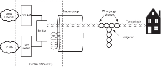
A copper twisted pair is a form of cabling in which two insulated copper conductors, typically 24 or 26 AWG (0.51 or 0.40 mm) in diameter, are twisted to reduce electromagnetic interference. Initially the conductors were wrapped in paper for insulation, but the lack of waterproofing made this material unsuitable for outside applications; eventually polyethylene became the dominant dielectric material and continues to be used [4]. Multiple insulated twisted pairs are grouped into a cable called a “binder group,” which emanates from Access Network Providers’ central office (CO) to residential areas and businesses. The lengths of the loops vary based on the population density of the served areas. Urban loop lengths tend to be short (less than 3000 ft), and suburban areas range in length from 3000 to 9000 ft and increase up to 18,000 ft typical in rural settings [4]. A single loop between the CO and customer is usually made up of pairs from sections of several binder cables, leading to different gauges and bridge taps. Bridge taps are open-circuit pairs, either intentionally placed along the main cable route in anticipation of new service connections or resulting from past disconnections and rearrangements (Figure 3.1). The changes in wire gauge and the presence of bridge taps impact the frequency response of the loop, potentially affecting the maximum bandwidth that an individual loop can support. Although ANPs have progressively remediated their copper loop infrastructure, a large variance in the length and quality still exists, resulting in a challenging environment to provide universal access to the highest bandwidths.
Figure 3.1. Copper twisted-pair wiring.
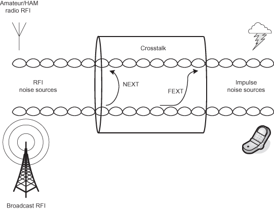
The twisted pair is often referred to a noise-limited transmission media due to the number and variety of impairments that are inflicted upon it (Figure 3.2), including:
- Attenuation, which is dependent on the type of dielectric material used, the wire gauge, type of twisting, and overall loop length. Attenuation increases with both signal frequency and loop length.
- Nonlinear phase response causing intersymbol interference.
- Echo resulting from full duplex communications across a single pair of conductors.
- Bridge taps that produce notches in the line transfer function.
- Crosstalk interference between pairs in the same binder group. Crosstalk is the dominant impairment experienced in DSL transmission [5]. This interference is caused by electromagnetic radiation from other pairs located in close proximity to the victim pair. The coupling of energy into the victim pair increases with frequency, making this more harmful for higher data rates. Two modes of crosstalk interference can impact the victim circuit: near-end crosstalk (NEXT), which is caused by signals traveling in opposite directions, and far-end crosstalk (FEXT), which is caused by signals traveling in the same direction. For longer loop lengths, FEXT is self-limiting due to the line attenuation; however, to support the new generation of high-bandwidth services, loop lengths are being systematically reduced, thereby increasing the negative effects of FEXT.
- Radio-frequency interference (RFI) is noise generated by radio transmitters such as amateur/HAM radios. These transmission frequencies are regulated and well known, allowing accommodation to be made in spectrum planning for high-speed data transmission over copper loops.
- Background noise is additive white Gaussian noise and represents the “noise floor.”
- Impulse noise is randomly occurring discrete noise “spikes,” narrowband or wideband in nature.
Figure 3.2. Impairment environment for a twisted pair.
International standards bodies such as the American National Standards Institute (ANSI), the European Telecommunications Standards Institute (ETSI), and the International Telecommunications Union (ITU) characterize impairments and provide mathematical models to aid in the evaluation of the noise performance of various DSL transmission schemes [6].
3.2.2 Digital Subscriber Line Overview
A digital subscriber line (DSL) is a modem technology that uses a copper twisted pair to transport high-bandwidth data. The term “xDSL” covers a number of technology variants that offer a competing blend of data rate, reach, and spectral compatibility. Examples are asymmetric DSL (ADSL), symmetric DSL (SDSL), high-bit-rate DSL (HDSL), and very-high-bit-rate DSL (VDSL). xDSL variants, speeds, distances, and standardization are shown in Table 3.1.
TABLE 3.1. DSL Comparison
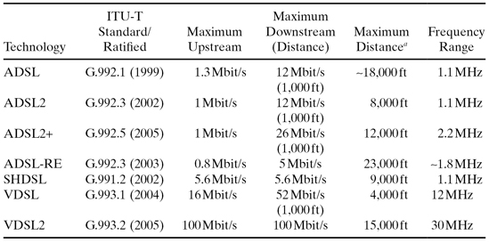
a Maximum distances obtainable, not maximum distance at which maximum speed is obtained. In practice, maximum distance at maximum speed is far less than maximum distance. For example, VDSL2 supports 100-Mbit/s operation at ∼1,500 ft, 50 Mbit/s at 3,000 ft and around 1 Mbit/s at 15,000 ft.
ADSL was the first internationally standardized and widely deployed DSL technology. The timeline illustrating the standards activities and corresponding deployment is shown in Figure 3.3. Motivated by video delivery, ADSL provided more downstream bandwidth than upstream, a characteristic present in many subsequent DSL variants. The asymmetric bandwidth distribution reduces NEXT, increasing practical loop lengths, which in turn made the service more economically viable and accelerated its deployment. Another important factor with ADSL deployment was the coexistence with the Plain Old Telephone Service (POTS). ADSL coexists with POTS (and narrowband ISDN) through frequency domain multiplexing, where the POTS service occupies frequencies between DC and 4 kHz, while the ADSL service occupies the upper frequencies from 25 kHz to 1.1 MHz.1 Through the use of frequency splitters at both the residence and central office (CO), the low-frequency POTS service is routed to the PSTN and the high-frequency DSL service is directed to the digital subscriber line access multiplexer (DSLAM). Frequency division duplexing (FDD) allocates the available ADSL bandwidth into upstream and downstream components. The upstream transmissions occupy the lower-frequency bands, from 25 kHz to 138 kHz, with the downstream bands beginning at 138 kHz and progressing up to 1.1 MHz, as shown in Figure 3.4. Given that attenuation increases with loop length and frequency, the downstream frequencies are more severely impacted as the loop length increases, reducing the downstream bandwidth.
Figure 3.3. DSL standardization timeline and worldwide deployment.
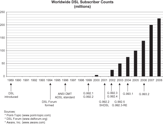
Figure 3.4. ADSL spectrum.
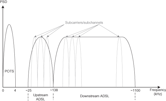
Early ADSL implementations contained different and incompatible modulation techniques. Two examples were carrierless amplitude phase (CAP) modulation and discrete multitone (DMT) modulation. CAP is a nonstandard variation of quadrature amplitude modulation (QAM). Whereas QAM modulates the amplitude of two quadrature carrier waves,2 CAP combines two pulse amplitude modulation signals that are filtered to produce a QAM signal. CAP uses a wide pass band, dividing the available spectrum into three regions: POTS (DC to 4 kHz), upstream (25 kHz to 160 kHz), and downstream (240 kHz to 1.1 MHz). Conversely, DMT provides multiple narrowband channels (224 downstream and 25 upstream in the case of ADSL), each with their own carrier. Each channel is individually modulated and combined using a QAM-like modulation, allowing multiple bits to be represented with a single QAM symbol. In QAM, each combination of amplitude and phase represents a unique combination of bits. A 64-symbol constellation (64-QAM) contains 64 unique combinations of amplitude and phase capable of representing any binary value consisting of 6 bits. Each channel has a 4-kHz frequency range and is capable of transporting up to 32 kbit/s. DMT provides advantages over competing modulation techniques such as simpler channel equalizers, bandwidth efficiency through the redistribution of bits to other subchannels, filterless frequency division multiplexing, good immunity properties to narrowband interference and performance in the presence of other line impairments such as wire gauge variations and bridged taps. The use of adaptive filtering leads to the principal disadvantage of DMT, that being the need to train the filter to ensure stability. Training is performed as part of the line initialization procedure prior to the line being ready to transmit or receive user data and may reoccur periodically if line conditions deteriorate. Further advanced signal processing techniques such as Trellis coding and interleaved forward error correcting (FEC) codes are used to improve noise susceptibility, leading to improved signal-to-noise ratios and longer practical loop lengths at nominal bandwidths. Although Bell Labs first developed digital technology using copper loops in the mid-1980s, it was not until the ratification of the DMT-based international standard G.992.1 [7] where CAP-based ADSL systems depreciated.
Although motivated by video delivery, ADSL did not offer bandwidth sufficient to support the prevalent video codecs of the day. To address these bandwidth limitations, G.992.3 [8] ADSL2 improves the data rates and reach, achieving as high as 12 Mbit/s at 600 ft while also being capable of supporting lower-bit-rate services out to 15,000 ft. ADSL2 includes features to improve line efficiency through reduced framing overhead [providing an all-digital (no POTS) mode of operation], supports mechanisms to transport both asynchronous transfer mode (ATM) and synchronous traffic types, and offers further increases in bandwidth through bonding of lines using inverse multiplexing for ATM (IMA). However, ADSL2 remained spectrally incompatible with ADSL, preventing the combination of ADSL and ADSL2 pairs in the same binder group. Spectral compatibility was later addressed in ADSL2+ [9], which also increased the downstream frequency band to 2.2 MHz with 512 subcarriers, resulting in 24-Mbps downstream bandwidth out to 3000 ft.
VDSL [10] and VDSL2 [11] represent the latest installment in the continuing evolution of DSL. Both standards provide a dramatic increase in potential data rates, with VDSL increasing the usable frequency spectrum to 12 MHz and VDSL2 pushing the upper end to 30 MHz. Such an increase in frequency affords downstream bit rates in excess of 50 Mbps, sufficient for multiple HD and SD video streams. As illustrated in Figure 3.5, VDSL introduced the use of segmented spectrum, where the upstream and downstream frequency ranges are no longer contiguous, in order to make VDSL more spectrally compatible with existing xDSL deployments.
Figure 3.5. VDSL spectrum.
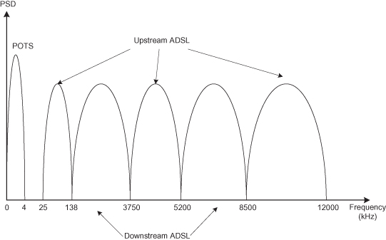
The move to native Ethernet encapsulation in VDSL, leveraging the work undertaken by IEEE 802.3ah Ethernet in the First Mile (EFM) taskforce, recognizes Ethernet’s growing importance outside of the LAN, reducing the interworking burden between the home network and Ethernet-based aggregation and backhaul networks. Asynchronous transfer mode (ATM) and synchronous transport remain legacy options. Although VDSL and VDSL2 data rates are attractive, they require short loop lengths to achieve their impressive performance. In both schemes, data rates drop considerably after 4000 ft [12]; and given that 18,000 ft is not uncommon in rural POTS lines, loop length reduction, through the deployment of active electronics deeper into the distribution network, is a necessary network evolution in order to deliver rates close to these stated maximums.
VDSL2 was approved by the International Telecommunications Union (ITU) in May 2006 as G.993.2 and is designed to provide both increases in data rates and reach compared to what is achievable with prior technologies. VDSL2 offers impressive raw data bandwidths, providing in excess of 25 Mbit/s over longer loops (4000–6000 ft) and symmetric data rates of 100 Mbit/s over short loops (less than 1000 ft) [12], an important data rate to address high-speed business services. Many of the improvements first contained in ADSL2+, including advanced diagnostics, the ability to dynamically alter bandwidth per channel, and superior impulse noise immunity, are also included in VDSL2. Impulse noise immunity is a particularly important property when transporting packetized video. Importantly, VDSL2 offers interoperability with a wide range of prior technology variants, including the original ADSL, ADSL2, and ADSL2+. VDSL2 utilizes the same modulation scheme as ADSL, discrete multitone (DMT), providing an increase to 4096 channels. A critical aspect of VDSL2 standardization has been the development of band plans that reflect the regional differences in frequency allocations while supporting both symmetric and asymmetric bandwidth services in same binder group.
3.2.3 Digital Subscriber Line (DSL) Reference Network Architecture
Although the copper loop is a crucial element in today’s wireline access network, it is not the only component required to deliver DSL service. This section will introduce a more network-centric view of emerging DSL networks, describing the equipment and companion networks necessary to deliver residential broadband services.
DSL network architectural decisions fall under the umbrella of the DSL Forum [13], now known as the Broadband Forum, an industry body responsible for promoting DSL technology worldwide through the development of technical specifications. With a membership consisting largely of network service providers and equipment vendors, the Broadband Forum develops specifications covering the requirements for equipment used in broadband DSL networks and defines common network reference architectures that guide service providers in the design of such networks. The forum has a strong history of producing relevant specifications spanning the entire evolution of broadband DSL technology. This section will examine in more detail one specification, Technical Report (TR) 101, “Migration to Ethernet-Based DSL Aggregation” [14], because it provides an overview of network architectural trends in residential wireline broadband deployments.
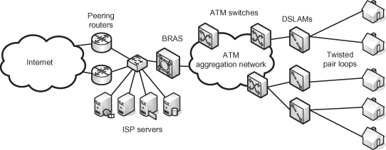
Conventional residential broadband DSL deployments have utilized asynchronous transfer mode (ATM) as an aggregation technology. Each subscriber would communicate with the Internet through Internet protocol (IP) connections encapsulated in one or more ATM-based permanent virtual circuits. Traffic from many thousands of subscribers would be aggregated by a network of ATM switches that would backhaul the traffic to be processed by a broadband remote access concentrator (BRAS). A BRAS is a centralized subscriber policy decision point in the network, responsible for subscriber authentication, authorization, and accounting (AAA) functions. The BRAS represented the first IP layer element in the network, the default gateway. Figure 3.6 illustrates an exemplary residential broadband deployment with ATM aggregation.
Figure 3.6. ATM-based residential DSL network architecture.
The push to support video broadcast services has driven the need to increase the bandwidth in the copper loop, which has consequential implications for the aggregation network in particular. To efficiently transport video, both the access and aggregation portions of the network require large quantities of bandwidth, quality of service guarantees, and efficient bandwidth utilization for wide-scale packetized video distribution. Ethernet has evolved to provide high connection speeds, packet-based quality of service, simple and efficient provisioning, native multicasting capabilities, and network redundancy suitable for deployments in carrier-grade networks. The technical capabilities of modern Ethernet transport and its associated compelling cost benefits has resulted in a wholesale migration away from ATM to Ethernet transport in new and upgraded residential broadband networks. The Broadband Forum specification TR-101 defines a reference network architecture (shown in Figure 3.7) and requirements for the network elements referenced in the architecture.
Figure 3.7. TR-101 Ethernet aggregation network architecture.
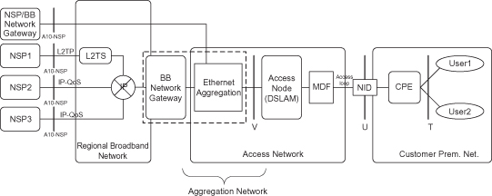
The reference network consists of a number of network elements (broadband network gateway, access node, network interface device, etc.), networks (regional, aggregation, access, and customer premise) and reference points (T, U, V, and A10). The reference points represent clear boundaries: either demarcation points, administrative boundaries, or network-specific traffic congestion points.
The broadband network gateway (BNG) is an Ethernet-centric IP router with subscriber AAA, quality of service, multicast and security functions. Additionally, the BNG is required to implement many of the legacy features commonly found in BRAS devices today, including point-to-point protocol (PPP)-based subscriber sessions over Ethernet via PPPoE [15] and bandwidth wholesaling using Layer 2 Tunneling Protocol (L2TP)-based tunneling [16]. The BNG occupies a critical location in the network, processing all the upstream and downstream subscriber traffic, and is evolving into a centralized policy decision-making and enforcement point. Such a control point performs service session identification and traffic management functions ensuring that no point in the aggregation and access network, including the copper loop, is overcommitted, thereby ensuring that the subscribers’ applications receive the required service and acceptable quality of experience.
The principal purpose of the aggregation network is unchanged in a native Ethernet deployment, that being to combine traffic from potentially thousands of subscribers over a residential neighborhood and backhaul the aggregated traffic to the BNG. The aggregation network consists of a series of interconnected Ethernet switches, connecting the BNG and digital subscriber line access multiplexer (DSLAM) devices. The Ethernet switches offer vastly superior switching capacities compared to the ATM equivalents and at a reduced relative cost. The Ethernet switches commonly used in such deployments provide IGMP snooping functionality [14], where the switch selectively reconfigures their multicast replication tables based on IGMP join/leaves sent upstream from the subscriber. The Internet Group Management Protocol (IGMP) is used in IP video broadcast applications to signal “channel change” events from a subscriber’s set-top box device. By providing snooping functionality in the aggregation network, bandwidth efficiencies may be realized by selectively replicating channels (IGMP groups) that are being watched by one or more subscribers. The aggregation network may serve as a point where “walled garden” content is injected into the network—for example, carrier branded video traffic. This is typically accomplished through the direct connection of video servers into the aggregation network. Traffic injected downstream of the BNG potentially invalidates policy decisions made at the BNG since that traffic is not visible to that network element. In such architectures it is necessary to separate the “walled garden” traffic from the high-speed Internet traffic through the use of multiple VLANs and traffic engineering to ensure that high-speed Internet traffic cannot interfere with the premium video content during periods of peak usage and congestion. The converse architecture is to carry all traffic, including the “walled garden” traffic, through the BNG, where it can be properly accounted and the correct policy decisions applied ensuring no downstream congestion.
The digital subscriber line access multiplexer (DSLAM) is the network element that bridges the service providers’ internal network and the subscriber through the copper loop. The DSLAM provides the physical layer DSL transceiver technology and adapts between the link layer protocol implemented on the copper loop and the protocol used in the aggregation network, which may involve ATM to Ethernet interworking. DSLAMs are evolving to provide high-density DSL line termination, increased line speed, advanced protocol features (such as IGMP snooping and proxy reporting), advanced remote management and diagnostic capabilities, and quality of service features to support the delivery of multiple services across the copper loop.
TR-101 and its predecessors define the U-reference point as being the customer premise located end of the copper loop. The network interface device (NID) implements the DSL physical layer and link layer encapsulation, such as IP over PPP over ATM or IP over PPP over Ethernet over ATM or simply IP over Ethernet. Figure 3.8, taken from TR-101 illustrates several possibilities.
Figure 3.8. Exemplary packet protocol stacks.
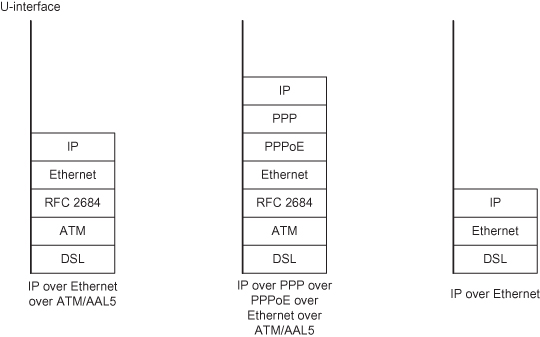
The U-reference point represents the demarcation point between the service providers network and the customer premise network. The CPE device interfaces with elements of the home network through Ethernet or some other preexisting wiring plant (twisted pair, coax, power, or wireless). The CPE may connect to several appliances in the home, including a video set-top box for video services, a phone (either PSTN via a gateway device or directly with VoIP phone), and the home computer or router-gateway device.
Often DSL networks are seen as simply the copper loop, but in reality they are sophisticated networks of networks, combining many discrete and heterogeneous networking technologies and elements in order to deliver services over a converged IP transport.
3.2.4 Futures
The last decade has seen remarkable increases in bandwidth delivered through century-old copper loop facilities, but surely we’re at the end of what can be reasonably extracted from this aging technology? Fortunately, some disagree and are actively investigating techniques to continue to mine copper loops’ hidden spectrum, even promising data rates greater than current and planned passive optical networks [3, 5].
The key strategy to increasing the available bandwidth in the copper loop is to minimize the impact of noise, particularly crosstalk. This is achieved through managing the spectrum of all transmitters in a binder group. There is a range of spectrum management techniques that deliver increasing benefits at the cost of increasing complexity. The simplest technique is static spectrum management, which defines rules that are applied to ensure spectral compatibility between all services and technologies that use pairs in the same binder group using worst-case spectra assumptions. Static spectrum management involves using predefined power spectrum density (PSD) masks to control the maximum allowed transmit power levels for any given frequency in a DSL system. Both VDSL and VDSL2 standards specify such masks, controlling the amount of power generated by a compliant transmitter across the entire range of operating frequencies.
Static spectrum management is a technique employed today to ensure that the current generation of services are deployable and do not hinder future DSL technology variants; however, it does not attempt to address the possibility of dynamically managing transmit power based on the specific local deployment conditions. Dynamic spectrum management [17] is a form of adaptive spectrum control that globally optimizes the spectra of different DSL systems deployed in one binder by tuning each transmitter’s power output to ensure that the bandwidth requirements are met with acceptable margin. The objective is to reduce transmission power on loops that can acceptably function with lower output power, coupling less energy into other victim loops, reducing crosstalk.
Dynamic spectrum management requires the ability to characterize the transmission properties of the loop such as line margin, transmit power, bits/tone tables, and insertion loss per tone. These parameters, combined with other line knowledge, such as loop length, bridge taps, and binder group identification, are input into a decision-making “authority” that performs the dynamic spectrum management function, predicting expected data rates and recommended margins and generating individual line control parameters such as PSD mask values and forward error correction (FEC) parameters. This involves calculating the desired transmission power necessary to cover the noise-to-signal curve as a function of frequency (NSF(f)). Increasing transmission power past this “optimal value” provides for more margin but offers no additional bandwidth gain; rather it translates to more energy coupled into the victim loop in the form of crosstalk interference. This approach results in the largest benefits on shorter loops, which require less power to achieve the desired bit rates. The final step in dynamic spectrum management is to configure each transmitter with the calculated control parameters. This three-step “characterize–calculate–update” procedure may be performed during line initialization and then executed periodically, modifying parameters as line conditions change. Since dynamic spectrum management automates much of the provisioning, maintenance, and operations of the DSL line, it has the secondary benefit of reducing the operating costs associated with the line [17].
Finally, an emerging DSL transmission technique called vectored transmission [3, 5, 17] aims to eliminate the effect of crosstalk all together, effectively creating a noise-free copper transmission medium potentially offering enormous data rates, limited only by analog and analog–digital convertor (ADC) circuit technology. The goal of vectored transmission is to eliminate far-end crosstalk (FEXT) introduced by other DSL transmissions through employing joint signal processing. FEXT introduced by other DSL systems is the dominant impairment constraining performance—especially as loop lengths decrease, resulting in less line attenuation. Vectored transmission coordinates both downstream and upstream transmissions, creating a vector of downstream transmitted signals and receiving a vector of upstream signals, conceptually treating the binder group pairs as a multiple-input–multiple-output (MIMO) transmission system. This coordinated transmission has been shown to provide in excess of 400 Mbps on loop lengths approaching 1200 ft [3].
Vectored transmissions rely on the ability to coordinate (in the time domain) all the downstream transmissions. All modems located on the DSLAMs DSL line card are synchronized to a common discrete multitone (DMT) symbol clock. In the upstream direction, through exploitation of the network timing reference transport in DSL, all customer premise modems synchronize their transmissions to the common symbol clock. The receivers on the DSLAM DSL line card can cancel both the upstream far-end and near-end crosstalk introduced by other DSL sources by performing a MIMO decision feedback within each tone. In the upstream direction, one of the users will have no crosstalk whatsoever on each tone. This user is decoded first. This users influence on the next user is constructed and removed from all subsequent users for each tone in the DMT transmission. Crosstalk is eliminated in the downstream direction by calculating the noise contribution of the other (coordinated) transmitters and pre-distorting the transmitted signal. Vectored transmission requires detailed knowledge of the exact crosstalk and noise autocorrelation matrix for the binder group in question, which requires extensions to the existing training sequence in order to generate these data in addition to the insertion loss and gain/phase information resulting from the line initialization procedure.
Vectored transmission is not the same as bonding mechanisms standardized in ADSL2. Link bonding is a data link layer multiplexing and demultiplexing technique that aggregates the bandwidth of multiple physical links to create a single virtual link with bandwidth aggregate of the constituent links. Vectoring is cogeneration and co-processing of the physical layer signals and is therefore independent of any bonding scheme employed.
3.2.5 Hybrid Fiber/Copper Networks
In order to deliver the high bandwidths required for video-rich triple-play services, access network providers (ANPs) must reduce the lengths of the copper loop, necessitating the deployment of active elements in the distribution network. This results in pushing fiber from the central office (CO) to DSLAMs located closer to the customer premise. These networks are commonly called fiber-to-the-node (FTTN), fiber-to-the-curb (FTTC), or fiber-to-the-building (FTTB), identifying the location of the DSLAM as being a curbside cabinet or in the basement of a multitenant building. Short copper loops then connect the DSLAM to the residence. Figure 3.9 illustrates the various FTTx models.
Figure 3.9. FTTx models.
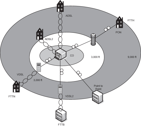
The decision to deploy a FTTN network versus a complete fiber-to-the-home (FTTH) network is extremely dependent on the business case, which takes into account the installed cost, operational cost, and expected service revenues. However, in some cases, it may not be possible to deploy a new building cabling system due to aesthetic or historical considerations. As a general observation, FTTN with VDSL2 loops, allowing the reuse of copper pairs, is more cost effective with regard to existing network infrastructure upgrades and allows faster time to market. FTTH can be more cost effective in completely new network deployments and promises lower operating costs [18].
One of the principal challenges in a mixed xDSL/FTTN network architecture is spectrum management—in particular, preventing the mixture of existing (longer-loop) DSL service and new, shorter-loop DSL service from a fiber-fed DSLAM in the same binder group [17]. Unless some form of spectrum management practices are adopted, the shorter high-speed loops create large amounts of crosstalk, which interfere with the longer, lower-rate CO feed loops. Without dynamic spectrum management, the transmitter on the shorter loop may be using orders of magnitude more power needed to achieve the required data rate.
Other considerations in FTTN deployments are less theoretical and more mundane. How does one power the remote DSLAMs? What environmental controls (if any) are required? How is lifeline POTS provided in the event of a power outage? Central office (CO) located equipment is deployed within a secure facility, with advanced heating and air conditioning, backup power supplies, and other building management systems, none of which are available in a sheet metal cabinet bolted to a concrete footing, located on a street corner. The challenge with deploying such complex, active electronics outside the controlled environment of the CO are numerous and require equipment specifically designed to withstand the environmental conditions found in non-air-conditioned cabinets or when mounted on poles or pedestals.
Finally, one often overlooked consideration is the additional burden placed on the operational divisions of the network operator. Deploying many smaller DSLAMs in the field may lead to higher operational costs associated with management and provisioning and in maintenance. These operational costs tend to be proportional to the number of network elements deployed. Operational costs are already a significant expense, with ANPs looking at reducing their effect on the business.
Even with these challenges, FTTN architectures represent a common network evolution path to enable to the bandwidth necessary for future services delivered over the existing copper loop.
The twisted-pair copper loop has formed the backbone of wireline access networks for more than a century. This enduring medium, coupled with enormous advances in signal processing technology, has evolved from providing basic telephony to being capable of delivering high-definition television broadcasts, video on demand, and other multimedia-content-rich services ensuring that the longevity of this particular type of wireline access network continues.
3.3 PASSIVE OPTICAL NETWORKS
This section will introduce a new variety of wireline access networks—the passive optical network (PON). Passive optical networks are topological tree point-to-multipoint (P2MP) optical distribution networks that have no active elements in their transmission paths. Their plentiful bandwidth and intrinsic P2MP nature provides for efficient video broadcasting, making PONs an ideal technology for next-generation wireline access networks. This section will introduce and describe a number of PON variants, with specific emphasis on Ethernet PON (EPON) technology. PON technology has been standardized in both the ITU-T [19, 20–23] and IEEE [24] organizations providing alternatives optimized for the carriage of legacy traffic or Ethernet frames. The IEEE’s EPON and the emerging 10 Gbit/s EPON [25] offer copious bandwidth while preserving the familiarity and cost benefits associated with Ethernet—arguably the world’s most successful networking technology.
3.3.1 Passive Optical Network Fundamentals
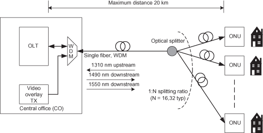
PON networks consist of fiber-optic cables for transmission, optical couplers for distribution, and active elements responsible for converting between the optical and electrical domains. Optic fiber is a very thin filament of glass, which acts as a waveguide allowing light to propagate with very little loss due to the principal of total internal reflection. The optical signal is distributed into branches using splitters, which replicate the optical signals received on an input across multiple outputs. Since splitters are passive elements, the optical power of any output signal is only a fraction of the optical power received on the input port. This reduction in optical power limits the fan-out of the network. Combiners perform the inverse function by combining optical signals from multiple inputs and transmitting the accumulated signal upstream. Combiners are highly directional, leaking very little optical power across input ports, a property referred to as directivity. The splitting and combining functions are integrated into a single element called an optical coupler. The final elements in a basic PON architecture are the optical line terminal (OLT) and optical network unit (ONU).3 These active elements are deployed within the central office and close to the residential or business premise respectively. The OLT and ONU “book-end” the optical distribution network, interfacing between the electrical and optical domains and performing functions typically required of the data link layer of the OSI reference model. The basic PON network architecture is shown in Figure 3.10.
Figure 3.10. Basic PON distribution network architecture.
Most PON technologies share a remarkable technical similarity with the selection of bearer protocol being their principal distinction. The ITU-T has standardized two PON architectures: broadband PON (BPON) based on asynchronous transfer mode (ATM) and more recently gigabit PON (GPON) that employs the Generic Encapsulation Method (GEM) for the native transport of time division multiplex (TDM), ATM, and the lightweight encapsulation of Ethernet frames. Ethernet PON, as standardized in the IEEE organization, provides a completely 802.3 compliant MAC interface, for the transmission and reception of Ethernet frames.
Due to the optical replication properties and directivity of the couplers, PONs are asymmetric in nature. In the downstream direction, the OLT frame transmission is broadcasted to all ONUs. Only frames explicitly addressed to an ONU are extracted and processed further. Using Ethernet as an analogy, in the downstream direction, a PON appears similar to a shared medium LAN. In the upstream direction, bandwidth is also shared between the ONUs, due to the optical couplers combining the ONU optical transmissions. This requires an arbitration scheme to coordinate access to the upstream transmission bandwidth to prevent collisions. Due to the directivity of the optical couplers, an ONU is unable to detect a collision, so although the upstream of a PON behaves as a shared medium, conventional contention-based mechanisms for resource arbitration such as carrier sense multiple access with collision detection (CSMA/CD) and carrier sense multiple access with collision avoidance (CSMA/CA) are difficult to implement. Rather than develop a cumbersome contention-based algorithm, both the ITU-T and IEEE have specified a time division multiple access (TDMA) scheme to avoid collisions at the optical level. Although differences exist in the details, BPON, GPON, and EPON share a common approach in dividing the upstream bandwidth into timeslots. Each timeslot represents a transmission window specified by a start time and either duration or stop time. The transmission timeslot is then granted by the OLT to the ONU using a specific bandwidth allocation algorithm. The OLT is free to allocate bandwidth to ONUs in any practical fashion, ranging from a static allocation to a dynamic one, based on the quantity of data that an ONU has to transmit. The relative merits of these algorithms are considered later in this chapter.
Once an ONU has been granted a transmission window, the ONU transmits up to the window size in a burst at the full physical layer data rate (1 Gbps in the case of EPON). When complete, the ONU ceases transmission including the disabling of the laser. The laser remains off during silence periods to prevent spontaneous emission noise from being injected in the upstream direction, potentially causing bit errors to other valid transmissions.
3.3.2 Ethernet Passive Optical Networks
Ethernet PON (EPON) emerged from the Ethernet in the First Mile (EFM) study group of the IEEE. The study group, constituted in 2001, was chartered with extending Ethernet technology into access networks suitable for residential and business subscribers, and it covered point-to-point (P2P) and point-to-multipoint (P2MP) architectures and Operations, Administration, and Maintenance (OAM) aspects of Ethernet networks. In accordance with IEEE procedures, the study group became the 802.3ah task force in September 2001 following the acceptance of the Project Authorization Request (PAR) [26]. One of the goals of the taskforce was to provide a 1-Gbps Ethernet service using P2MP passive optical networking supporting a minimum splitting ratio of 1 : 16, while preserving the existing frame format, media access control (MAC) layer and media independent interface (MII) of standard 802.3 Ethernet for distances of 10 km or more (Table 3.2).
TABLE 3.2. EPON PAR Goals
| Technical | Objective |
| Frame format | 802.3 standard format and encoding |
| Line rates | Standard Ethernet rates, 1000 Mbit/s |
| Fiber | Single fiber, single mode (SMF) |
| Distances | 10 km minimum |
| PMD | Investigate 1310/1310, 15xx/1310, and ITU 983.3 |
| Splitting ratio | 1:16 min |
| Connector | SC, investigate high-density connectors like LC |
Adhering to these goals and minimizing the modifications to the physical and physical medium-dependent (PMD) sublayers would promote rapid adoption through the use of high-volume, low-cost 1-Gbps optical and semiconductor components [26].
The 802.3ah taskforce successfully completed their standards activity with the production of the 802.3ah-2004 document. This work has since been subsumed into Section 5 of the 2005 Edition of IEEE 802.3 standard [24] (Figure 3.11). The 802.3ah EPON standardizes a 1-Gbit/s symmetric (1 Gbps downstream and 1 Gbit/s upstream) PON network that employs two wavelengths over a single fiber (1490 nm downstream and 1310 nm upstream) for data transmission, with the option of a further downstream wavelength (1550 nm) reserved for additional services such as analog video broadcast. With an optical power budget of 24 dB, distances of 20 km can be obtained, with a splitting ratio of 1 : 16. Frames are encapsulated in the standard 802.3 format and are encoded using 8b/10b line codes.
Figure 3.11. IEEE EPON protocol layers and network capabilities.
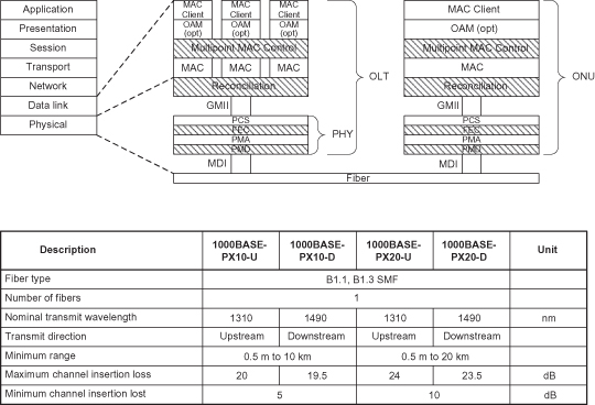
The standard 802.3 Ethernet MAC supports two operating modes: a shared-medium, single-collision domain and a full-duplex point-to-point topology. Upstream characteristics of a PON exhibit aspects of both modes. The IEEE has specified a TDMA scheme, coupled with a P2P logical topology emulation to simulate a P2P connection based upon the shared upstream bandwidth of the PON. The key extension proposed by the taskforce and adopted by the standard is the creation of an additional MAC control protocol: Multipoint MAC Control Protocol (MPCP). MPCP is a real-time control protocol that is responsible for manipulation of the MAC sublayer operation. MPCP extends the existing pause-based flow control of the MAC Control sublayer to include facilities for network clock synchronization, ONU resource management, and the discovery, registration, and initialization of ONUs. MAC Control Protocol frames are distinguished from other MAC frames by a specific value (88-08 hexadecimal) in the length/type field. MPCP frames are further distinguished by a specific 16-bit opcode value that follows the length/type field. This is shown in Figure 3.12.
Figure 3.12. MAC control frame format.
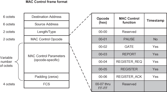
MPCP defines five additional MAC control frames:
- GATE: A grant of a transmission window made to the recipient.
- REPORT: Notification of a pending transmission from the sender.
- REGISTER_REQ: A request for the sender to be recognized as participating in the gated transmission protocol.
- REGISTER: A notification that the recipient is recognized to participate in the gated transmission protocol.
- REGISTER_ACK: A notification that the sending station acknowledges its participation in the gated transmission protocol.
TDMA bandwidth allocation mechanisms require all transmitting nodes to be synchronized to a common time base in order to avoid collisions. Given that each ONU stores frames received from a subscribers’ network, waiting for a granted transmission opportunity, each ONU must have a common and consistent view of “time.” The ONUs achieve clock synchronization through a timestamp that is inserted in the MPCP GATE message that is transmitted by the OLT. The timestamp is a monotonically increasing 32-bit counter, incremented every 16 ns (referred to as the time_quanta). The timestamp field is populated by the OLT and represents the transmission time of the first byte of the destination address of the GATE message. When the GATE message is received, the ONU sets the MPCP local clock to the value contained in the timestamp field. The MPCP local clock is incremented by a clock recovered from the incoming data stream. Since the line contains IDLE characters during periods of silence, the clock can be continuously recovered, minimizing wander. Although this technique requires strict control of the delay variation within the OLT, which can be no more than 16-bit times (1 time_quanta) through the RS, PCS, and PMA sublayers, it does allow the OLT to continue to use a conventional +/−100-ppm clock source.
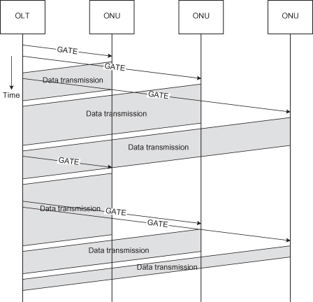
Resource management consists of the assignment of upstream bandwidth to an ONU, upstream scheduling to decide ONU transmission order, and upstream bandwidth allocation to determine timeslot length. MPCP uses the GATE and REPORT MPCP control messages to perform resource management and coordinate access to upstream bandwidth. The GATE message is sent downstream from the OLT to a specific ONU granting a defined transmission opportunity to the ONU. The timeslot is defined by start time and transmission duration. On reception of the GATE, the ONU synchronizes its MPCP local clock and selects a frame (or sequence of frames) for transmission. A single GATE message can specify up to four independent granted timeslots. Timeslot allocation is carefully pipelined in order to minimize the time to walk all ONUs and maximize network utilization. The pipelining effectively eliminates the overhead of the GATE message transmission and processing; however, it does require knowledge of the round-trip time (RTT) to each ONU. The ONU transmits the REPORT message to the OLT to request subsequent transmissions opportunities. The pipelined transmission timing of the GATE and REPORT messages is illustrated in Figure 3.13.
Figure 3.13. Pipelined GATE/data transmission.
The REPORT message contains queue occupancy (in units of time_quanta) information indicating the amount of transmission bandwidth that the ONU is requesting in the next scheduling epoch. The OLT may use this information in the execution of the bandwidth allocation algorithm. A report message can specify occupancy of up to 8 queues within a grouping, called a “queue set.” A single REPORT message can contain up to 13 separate “queue sets.” The actual bandwidth allocation algorithm is outside the scope of the IEEE standard and remains implementation-dependent. This has provided a rich research topic as studies have tried to balance competing goals of maximizing network utilization, service quality assurances and complexity [27–30].
The third responsibility of MPCP is to coordinate the auto-discovery of ONUs. Given that ONUs are mandated not to transmit any data unless explicitly granted timeslots by the OLT, a procedure is required for an OLT to discover newly activated ONUs. This protocol is responsible for performing the initial discovery, activation handshake, measuring the round-trip time, learning the ONUs individual 48-bit MAC address, and providing configuration information to enable successful bidirectional communications. For this, a four-phase handshake procedure is built using the MPCP control messages describe prior.
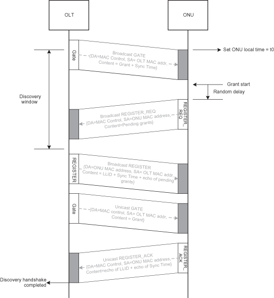
- The first step involves the OLT allocating a discovery timeslot. The discovery timeslot has special semantics, whereas a normal timeslot represents a transmission opportunity for a specific ONU; a discovery timeslot is a transmission opportunity for all uninitialized ONUs. During a discovery timeslot, the OLT broadcasts a discovery GATE, advertising the start time and duration of the discovery timeslot. The discovery GATE also contains the OLT timestamp.
- All known and initialized ONUs will discard the discovery GATE message. An uninitialized ONU will accept the broadcasted discovery GATE, synchronizing its MPCP local clock and wait until the designated transmission time. To avoid the expected collisions from more than one uninitialized ONU transmitting at the discovery timeslot start time, the protocol requires each ONU to wait an additional random amount of time before commencing transmission. The ONU transmits a REGISTER_REQ message that contains the source address and the ONU timestamp of the first byte of destination MAC address. The REGISTER_REQ message is received by the OLT, which allows it to calculate the round-trip time (RTT) for the ONU. The RTT is the numerical difference between the time of reception of the REGISTER_REQ and the timestamp included in the message. This is shown in Figure 3.14.
- The OLT replies to the REGISTER_REG with a REGISTER message assigning a logical link identifier (LLID). The LLID allows the ONU to discriminate unicast frames addressed to it. The OLT immediately sends a unicast GATE message to the newly activated ONU.
- Once the ONU receives the REGISTER and the GATE message, it replies with a REGISTER_ACK (in the timeslot allocated by the GATE message) to complete the process.
Figure 3.14. Round-trip calculation.
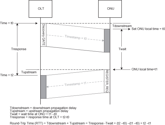
Figure 3.15 graphically represents the autodiscovery procedure.
Figure 3.15. Discovery handshake.
The discovery process is an overhead that consumes bandwidth from the overall network transmissions, thereby reducing utilization. The size and periodicity of the discovery timeslots must balance the time to discover and initialize a new ONU versus the overall decrease in network utilization due to the lost transmission opportunities within the discovery timeslot periods.
The IEEE standard [24] requires a logical topology emulation (LTE) function in order to fully comply with the requirements outlined in 802.1D concerning Ethernet bridging devices. In addition to the shared-medium/single-collision domain and full-duplex point-to-point operating modes of the 802.3 MAC, 802.1D compliant bridges do not forward frames back out the source port. If an OLT is to be considered an 802.1D-compliant bridge, the PON must be considered either a full duplex point-to-point topology or a completely shared-medium/single-collision domain topology. The 802.3 standard [24] defines a logical topology emulation function that resides below the MAC sublayer (thereby being transparent to the MAC layer), which allows a PON to mimic either topology. The 802.3 standard [24] only specifies the behavior of the full-duplex point-to-point model but is unwilling to lose the enormous benefit of single-copy broadcast in the downstream; it adds a single-copy broadcast (SCB) MAC port to the architecture, used for the logical broadcasting of frames to all downstream ONUs.
The LTE operates by assigning a logical link identifier (LLID) to each ONU during the auto-discovery process. Frames are transmitted with the 16-bit LLID embedded in a modified preamble (protected by a CRC). Frames matching the assigned LLID (or matching a broadcast LLID) are accepted by the ONU, and all other frames are discarded. In the upstream direction the ONU inserts the LLID into the preamble, allowing the OLT to “steer” the frame to a virtual MAC specific to the transmitting ONU, thereby emulating a full duplex point-to-point topology.
In order to improve physical reach of the optical distribution network, increase the splitting ratio, or simply improve the reliability of the communications channel, the IEEE included an optional forward error correction (FEC) mechanism. FEC provides the receiver with the ability to detect and even correct bit errors that occur during transmission. The encoder adds parity information to the frame to allow the decoder to detect the bit errors and reconstitute the correct information sequence. The FEC procedure selected by the 802.3ah taskforce is identical to that used in other PON technologies, most notably GPON, which is a block-based Reed–Solomon algorithm that adds 16 parity bytes for each 239-byte block frame data [22]. The IEEE standard defines a procedure to segment the 802.3 Ethernet frame into a sequence of 239 byte blocks. The final block is padded with zeros if necessary for the benefit of the FEC parity calculation. These padding bytes are not transmitted with the frame. The parity symbols are grouped together and transmitted at the end of the frame, leaving the 802.3 frame format unchanged. This decision represents a major advantage of the standardized frame-based technique, permitting interworking with non-FEC-enabled devices.
The final topic that deserves some discussion concerns privacy in EPON. Given that all frames are passively replicated to ONUs in the downstream direction and that ONUs rely on logical but not physical mechanisms for frame filtering, circumventing these logical restrictions would allow an ONU to eavesdrop on all downstream transmissions. Unlike local area networks, access networks consist of noncooperating users requiring privacy of communications; therefore it is surprising that the 802.3ah taskforce did not require an optional encryption component. However, many commercial network equipment manufacturers include encryption in both upstream and downstream directions enabled by the common availability of semiconductor products that integrate 128-bit advanced encryption standard (AES) encryption schemes [31, 32].
The rapid specification and commercialization of EPON technology is a testament to the flexibility and longevity of the 802.3 standard. Ethernet is the pervasive networking technology of choice for next-generation telecom networks, and EPON is one important step to bridging the domains of the subscriber’s home LAN and the Ethernet domain of the metro and long-haul networks. The commercial future is exceedingly bright, due to the IEEE 802.3ah taskforces’ efforts in maintaining backward compatibility with the billions of deployed Ethernet ports.
3.3.3 ITU-T Passive Optical Networks
Several PON technologies predate the IEEE EPON standardization efforts. These earlier PON technologies have been defined under the auspices of the International Telecommunications Union, Telecommunication Standardization Sector (ITU-T). In 1995 a group consisting of seven leading network service providers formed a special interest group called the Full Service Access Network (FSAN) group [33]. The FSAN had the worthy goal of creating a unified set of technical specifications covering a next-generation access network capable of delivering an expanded range of packet services in addition to the legacy transport of time division multiplex (TDM) and asynchronous transfer mode (ATM) services. The FSAN members developed a PON specification using ATM as the bearer protocol, known as asynchronous PON or APON. In 1997, the APON specification, now renamed broadband PON (BPON), was submitted to the ITU-T for standards consideration and became the G.983 series recommendations [19]. The original PON specification provided a symmetric 155-Mbit/s (155 Mbit/s downstream and 155 Mbit/s upstream) transport, which has been expanded to include an asymmetric 622-Mbit/s–155-Mbit/s and symmetric 622-Mbit/s data rates.
FSAN continued to define a minimum functional subset of the capabilities embodied in the recommendations called the Common Technical Specification (CTS). By proposing a common reduced feature set, FSAN expected lower equipment and operational costs due to lower equipment complexity and higher volumes. Although an admirable goal, the demands of efficient transport of legacy traffic (TDM and ATM) resulted in a scheme unsuited to the requirements of the predominant traffic type, namely, Ethernet. Addressing this limitation has been a focus of BPONs’ successor, gigabit PON (GPON).
3.3.3.1 Broadband PON.
The G.983 family of recommendations [19] specify a PON network with a 20-km reach, using either a single-fiber (two wavelengths) or a dual-fiber deployment, with a maximum splitting ratio of 1 : 32. As described earlier, BPON supports symmetric 155-Mbit/s, symmetric 622-Mbit/s, and asymmetric 622-Mbit/s–155-Mbit/s data rates. BPON differs from EPON in that it has an asymmetric framing structure: The frame formats used in the downstream and upstream differ, as shown in Figure 3.16.
Figure 3.16. 622-Mbit/s–155-Mbit/s BPON frame format.
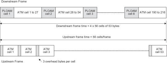
The downstream (from OLT to ONU) is based on a pseudo-frame of 56 ATM cells. Each pseudo-frame consists of 54 “user” cells and two physical layer operations, administration and maintenance (PLOAM) cells. As with other PON technologies, the downstream frame is passively replicated to all ONUs, with a particular ONU extracting cells with a matching VPI/VCI. The upstream frame format is a 56-byte cell consisting of a 3-byte preamble and a 53-byte ATM cell.
Broadband PONs arbitrate upstream bandwidth using a time division multiple access (TDMA) mechanism, where the OLT allocates timeslots to the ONU through a transmission of a GRANT PLOAM cell downstream. As part of the ONU discovery and calibration procedure, the OLT performs a “ranging” operation that estimates the round-trip time of each ONU. The OLT calculates an equalization delay that normalizes all ONUs to a delay equivalent of a uniform distance of 20 km from the OLT. The OLT provides the specific equalization delay to each ONU, thereby ensuring collision-free operation in the upstream direction.
Due to its early development, BPONs have been successfully deployed by NTT in Japan and by the former Bell South (now AT&T) in the United States, which has offered commercial services based on BPON since 1999 [34]; however, new PON deployments are based on the newer EPON and GPON technologies. Although surpassed by technology, BPONs represent an important contribution, providing many of the technical underpinnings for its successors: GPON and EPON.
3.3.3.2 Gigabit PON.
FSAN and the ITU-T have continued to evolve the initial BPON to gigabit rates with the introduction of the G.984 series of recommendations standardizing gigabit PON (GPON). The general characteristics and the physical layer aspects of GPON are defined recommendations G.984.1 [20] and G.984.2 [21], respectively. These recommendations include the specification of 1.244-Gbit/s and 2.488-Gbit/s transmission rates for upstream and downstream. When included with the existing BPON data transmission rates, a total of seven rate options are available, providing the access network provider (ANP) considerable flexibility to engineer the access network. GPON continues the specification of dual or single-fiber (dual wavelength 1490 nm downstream, and 1310 nm upstream) systems. Common to other PON variants is an additional 1550-nm wavelength provided for overlay services. The GPON protocols can support splitting ratios up to 1 : 128 and a logical reach of 60 km, but these are physically constrained to 1 : 64 and 20 km due to the available optical power budget.
Recommendation G.984.3 [22] defines the transmission convergence (TC) function. Transmission convergence defines how user data are adapted into the PMD sublayer and includes network clock synchronization, framing formats, ranging procedures, and MAC layer functionality. This recommendation is also responsible for defining the basic management and control functions of the MAC, including auto-discovery, health and performance monitoring, and the configuration of optional features such as FEC and encryption. We will examine G.983.3 in more detail.
3.3.3.2.1 GPON Transmission Convergence.
The transmission convergence layer specification of GPON defines the GPON TC (GTC), a mechanism for transporting user traffic across the GPON service (Figure 3.17). Currently, the standard provides both cell-based and frame-based techniques; and although both GPON and BPON support an ATM transmission convergence sublayer, these systems are not interoperable at common transmission rates. The inclusion of the Generic Encapsulation Method (GEM) addresses the prior inefficiencies with segmentation and reassembly of variable-length frames required by cell-based schemes. GEM borrows much from the Generic Framing Procedure (GFP) defined in ITU-T recommendation G.7041 [35]. GFP is a multiplexing technique that allows the mapping of variable-length user data into SONET/SDH or equivalent transport networks.
Figure 3.17. GPON transmission convergence sublayer.
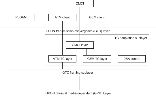
The GTC is further subdivided into two sublayers, the GTC framing sublayer and the TC adaptation sublayer. The framing sublayer is responsible for synchronization, encryption, FEC, MAC, and physical layer OAM (PLOAM). The adaptation sublayer specifies the two TC schemes, dynamic bandwidth allocation, and the definition of a management and control interface to the ONU (OMCI). Management aspects on the ONU are captured in G.984.4 [23].
GPON, similar to BPON, maintains an asymmetric framing structure, where the downstream frame format is different from the upstream format. In the downstream direction, the frame consists of a header portion [referred to as the physical control block downstream (PCBd)] and a user payload portion. The downstream frame is transmitted every 125 µs, independent of the transmission rate, resulting in a smaller user payload portion of the frame when transmitted with lower data rates. The 125-µs periodicity of the downstream transmissions allows the ONUs to derive an 8-kHz reference clock, which is particularly useful when interworking with TDM services. Recommendation G.984.3 includes a ranging procedure similar to BPON, where the OLT equalizes the ONU to a delay equivalent to a distance of 20 km. This equalization is provided to the ONU during the activation process.
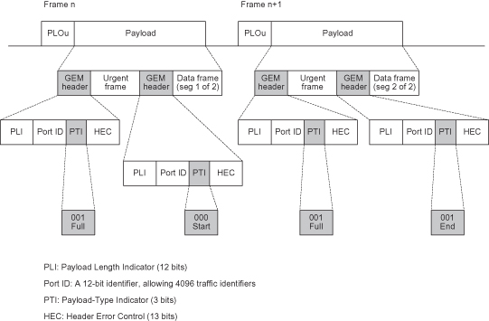
As shown in Figure 3.18, the PCBd contains framing/preamble fields to enable physical layer synchronization and framing. This field is not scrambled. The 4-byte Ident field is used as part of the data encryption system. The PLOAM field contains a 13-byte embedded PLOAM message. Finally, the PCBd contains a scalar array of bandwidth allocations called the bandwidth map (BWmap). The BWmap contains an array of allocation structures. Each allocation structure consists of a queue identifier (alloc_ID) and pair of start and stop points. Each record is protected by a CRC that is capable of 2-bit error detection and single-bit error correction. The upstream framing structure consists of a variable number of header fields and a payload section (Figure 3.19). The upstream frame length is identical to the downstream length for all data rates. Each frame contains a number of transmissions from one or more ONUs coordinated by the downstream BWmap. The downstream payload section contains ATM cells, GEM frames, or both.
Figure 3.18. Downstream frame format.
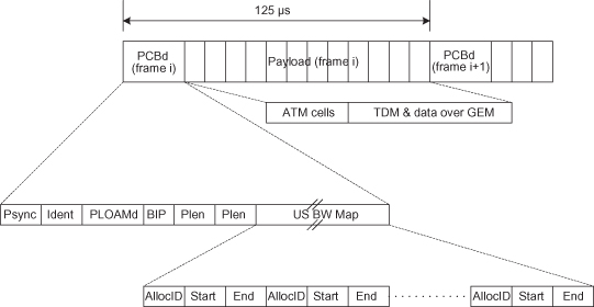
Figure 3.19. GPON upstream frame format.
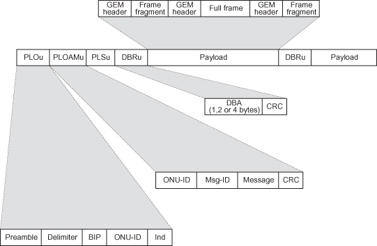
The upstream frame format provides for a variable number of headers to be included in the transmission. Flag fields contained in the allocation record of the BWmap specify the headers included in the frame. The four types of headers are:
- Physical Layer Overhead (PLOu): This header is mandatory and contains preamble, delimiters, and ONU identification information. The various fields in this header are protected by a bit interleaved parity (BIP).
- Physical Layer Operations, Administration, and Maintenance (PLOAMu): This header is optional, when included contains a 13-byte PLOAM message.
- Power Level Sequence (PLSu): This optional header is intended to allow for the adjustment of ONU power levels to reduce optical dynamic range as seen by the OLT.
- Dynamic Bandwidth Report (DBRu): An optional header that reports the ONUs bandwidth requirements. It may be formatted as a 1-, 2-, or 4-byte report, depending on the traffic types being reported. The reporting mode specifies a queue occupancy (in 48-byte quanta), a committed/peak rate tuple, or a combination of both.
The upstream payload section contains ATM cells, GEM frames, or DBA reports.
3.3.3.2.2 GEM Encapsulation.
The Generic Encapsulation Method (GEM) is a frame-based mechanism capable of transporting Ethernet, TDM, and ATM in a single transport container using their native frame formats. A GEM frame consists of a 5-byte GEM header and user payload portion. The GEM header consists of a payload length field, a 12-bit port ID (which facilitates flow multiplexing), and a payload-type indicator (PTI). A 13-bit HEC field providing both error detection/correction capabilities and frame delineation is also included in the header.
An important distinction between EPON and GEM encapsulated Ethernet frames found in GPON is that GEM allows a client frame to be fragmented across multiple GEM payloads, whereas 802.3 precludes such fragmentation. This ability allows GEM to transport TDM while meeting the strict latency and jitter requirements by preempting non-urgent traffic with more time-sensitive TDM data. This fragmentation is shown in Figure 3.20.
Figure 3.20. GEM header and fragmentation example.
GEM provides a connection oriented bidirectional communications channel identified by port ID. It is used to transport a user service flow between then ONU and OLT. GEM ports are aggregated into logical entities called traffic containers or T-Conts, which are identified by an Allocation ID (alloc-ID). Figure 3.21 represents the hierarchy of flows, ports, and containers.
Figure 3.21. GEM traffic classification hierarchy.
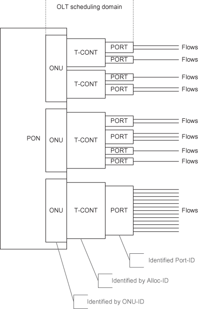
As with other PON variants, the OLT is responsible for scheduling the upstream transmission in GPON with a scheme that provides for an extremely fine-grained traffic control. Rather than granting a transmission opportunity to a particular ONU, with the ONU selecting which frame to transmit from a set of pending frames, the OLT in GPON is responsible for scheduling each “traffic container” (or T-Cont) for each ONU. This fine-grained scheduling is facilitated by the ONU reporting the buffer occupancy of each T-Cont. A T-Cont is analogous to a class of service, which aggregates one or more physical queues containing traffic that requires similar treatment. The T-Cont treats the aggregate as a single entity with a specific requirement such as aggregated bandwidth, latency, or jitter. The benefits of such a fine-grained scheme are improved network efficiency, reduced complexity (and therefore reduced cost) in the ONU, and the ability to provide service level agreements to all subscribers. The flipside of this approach is the potential for a significant amount of upstream and downstream bandwidth consumed for reporting and granting bandwidth for each T-Cont across all ONUs. Recommendation G.984.3 define five types of T-Conts corresponding to the different classes of service or scheduling modes:
- TCONT1: Legacy TDM emulation, providing unsolicited grants of bandwidth via a fixed payload size scheduled at periodic intervals. TCONT1 bandwidth is excluded from the dynamic bandwidth algorithm of the OLT.
- TCONT2: Intended for variable bit rate (VBR) traffic that has both a delay and throughput requirement. This TCONT is suitable for packetized voice and video.
- TCONT3: This traffic container is considered to be “better than best effort,” meaning that it is opportunistically scheduled (it receives excess bandwidth when available) but receives a minimum bandwidth guarantee, preventing complete starvation.
- TCONT4: Considered as “best effort,” opportunistically scheduled, with no minimum bandwidth guarantee.
- TCONT5: This is a superset of two or more of the other TCONTs. TCONT5 is intended to provide an aggregate bandwidth per ONU. The determination of which alloc-ID to transmit is at the discretion of the ONU.
ONUs report the amount of data waiting in a T-Cont buffer via the DBRu field in the upstream frame. The reporting mode is specific to the TCONT being reported. Mode 0 reports a single byte that represents the number of 48-byte blocks awaiting transmission. This mode is useful for best effort (TCONT4) traffic and is the only mandatory reporting mode specified by the recommendation. Reporting mode 1 is intended to report TCONT3 and TCONT5 bandwidth requirements. Mode 1 uses two bytes: The first byte represents the data requirement in terms of peak rate tokens, whereas the second byte reports the data requirements in sustained rate tokens. The ONU is required to police the incoming data rate with a token bucket policer. Mode 2 uses a 4-byte reporting record useful for TCONT5. Mode 2 encodes TCONT2 cells in the first byte. The second and third bytes contain TCONT3 peak and sustained transmission requirements, and the fourth byte contains the TCONT4 queue length. The OLT MAC performs the scheduling decision based on the upstream dynamic bandwidth reports received during the earlier epoch and long-term traffic limits applicable to each ONU, thus ensuring that all ONUs receive a minimum service even under heavily loaded operation.
3.3.4 Resource Management in PONS
The shared nature of upstream bandwidth in PONs results in challenges ensuring equitable allocation of bandwidth to ONUs while honoring service guarantees and simultaneously maintaining high network utilization. Proposing algorithms that address these challenges has been a rich research topic [27–30]. This section will introduce the concept of resource management in a PON network.
From the prior descriptions of EPON and GPON, resource management begins with resource negotiation. Both EPON and GPON allow an ONU to request upstream transmission bandwidth with the OLT granting the resource in accordance with some predefined policy. In an 802.3ah-compliant EPON, this is achieved through the REPORT/GATE MPCP message protocol exchange, and in a G.984 GPON the DBRu/BWmap mechanism accomplishes the same objective.
The second facet of resource management is selecting which ONU to grant the upstream bandwidth. This decision can be tightly coupled with the class of service that the ONU is requesting to send, as is the case with GPON, or it can be completely decoupled, as is the case with a simple round-robin scheduler. There is one aspect of resource management that is not completely specified in either EPON or GPON standards: the precise allocation of bandwidth to an ONU or class of service traffic of a particular ONU. This is referred to as dynamic bandwidth allocation (DBA). DBA algorithms take into consideration the amount and type of data buffered in the ONU awaiting transmission and allows the OLT to dynamically alter the amount of bandwidth granted to an ONU to service this buffered data. DBA algorithms are an important mechanism to improve upstream network utilization, improving throughput. Access networks are bursty in nature due to the relatively modest amount of traffic aggregation due to the limited number of subscribers. This is unlike metro and backbone networks that benefit from aggregating a large number of independent traffic sources, effectively “smoothing” the cumulative offered load. Examining conventional Ethernet traffic profiles [36] demonstrates that individual traffic sources are extremely bursty, with a self-similar nature, resulting in considerably variable bandwidth requirements over time. Static allocation of upstream bandwidths tends to underutilize links, resulting in poor throughput, increased packet latency, and potentially packet loss even at low utilizations. Employing DBA algorithms results in the network adapting to the instantaneous bandwidth requirements, allowing a greater degree of statistical multiplexing and hence higher network utilization resulting in higher throughput, lower latency, and packet loss.
3.3.4.1 IPACT.
A common statistical multiplexing algorithm described in the literature [28, 30] is Interleaved Polling with Adaptive Cycle Time (IPACT). IPACT polls ONUs individually and issues transmission grants in a round-robin fashion. The grant window is equal to the backlog from the previous reporting epoch, thereby ensuring that the bandwidth is allocated dynamically based on queue occupancy. To prevent a single ONU from a monopolizing upstream bandwidth, an ONU is assigned a maximum transmission window (MTW). Once the ONU has exhausted its MTW, it is not granted any further bandwidth until the next polling cycle. There are a number of algorithmic variants that differ in the treatment of MTW:
- Fixed: The DBA ignores the requested window size, instead granting MTW with a constant polling interval.
- Limited: The DBA grants the requested window size, up to the MTW limit.
- Credit: The DBA grants the requested window size plus a constant credit that is proportional to the window size.
- Elastic: The DBA attempts to overcome the limitation of only granting an MTW per polling cycle. The OLT integrates over successive polling cycles; this ensures that over the last N grants, the assigned bandwidth does not exceed N × MTW, where N is equal to the number of ONUs.
3.3.4.2 Class of Service Schemes.
Other scheduling algorithms attempt to take into consideration the type of traffic that the ONU is sending. In some circumstances, providing an aggregate bandwidth to an ONU may not be sufficient to ensure that all traffic receives the treatment required. For example, voice traffic imposes a strict delay budget on the access network: ITU-T Recommendation G.114, One-Way Transmission Time [37], specifies a 1.5-ms one-way propagation delay in the access network. Irrespective of the amount of bandwidth an ONU is granted, if it can be delayed for greater than 1.5 ms, voice quality could be impacted. Families of scheduling algorithms that consider not only bandwidth but also latency, jitter, and packet loss requirements, can be classified as providing either absolute Quality of Service (QoS) or relative QoS. Absolute assurances are quantitative and quantify the SLA requirements of the traffic in terms of bandwidth, latency, and packet loss ratio. Relative QoS assurances characterize the service guarantees in qualitative terms such as “low loss,” “low latency,” and whether bandwidth is assured. The various classes are scheduled in such a manner that their relative importance is preserved. In general terms, the absolute assurance schemes can be complex and may involve elements of admission control and per class rate control and shaping.
Although much valuable research has been conducted in this area, it is important to step back and analyze the need for such sophisticated techniques in the upstream direction, particularly in the context of residential broadband access networks. In the downstream direction, services for voice (low latency and low bandwidth), video (assured bandwidth with low loss), and a best-effort Internet access are clearly required. In the upstream direction, a simple high-priority service (for voice) and a best-effort Internet access service would seem sufficient for most subscriber services. Other often-cited classes of service for applications such as gaming and consumer-oriented video-conferencing offer marginal benefit and even more marginal revenue potential. Admittedly, business-oriented services may require more elaborate upstream bandwidth allocation to cater for TDM-based PBX traffic and a diversity in data traffic classes of service. These scenarios may warrant the additional complexity and cost associated with sophisticated upstream QoS mechanisms, allowing a PON to offer true service replacement.
3.3.5 Future Trends
Passive optical networks promise orders of magnitude more bandwidth than current day copper-based access networks; however, work is well underway examining future areas for expansion.
TDM-based PON networks can scale in multiple dimensions. Greater optical power budgets would yield higher splitting ratios and/or longer physical reach, greatly expanding the number of customers served by a single fiber. This is an important factor in determining the economic viability of a PON network, because it allows the cost to be amortized over a larger subscriber base, reducing the cost per subscriber. Amplification is another way of achieving the same goals, but with the loss of a valuable property of the optical distribution network (ODN)—its passive nature. Another scaling dimension is rate. International standards bodies are busy working on defining higher rate PONs, the IEEE is defining a 10-Gbit/s Ethernet PON standard through the P802.3av working group [25] with the goal of providing both a symmetric 10-Gbit/s and asymmetric 10-Gbit/s downstream–1-Gbit/s upstream network architecture. The ITU-T is considering similar extensions to the GPON recommendations to increase rates to 10 Gbit/s and beyond. Incrementally evolving the PON through rate increases preserves the investment in the current ODN and leverages its passive nature and rate independence, requiring only an upgrade to the optoelectronics of the OLT and ONUs.
Wave division multiplex (WDM) PONs [38] scale past the limits offered by the TDM PONs of today, as well as past the proposed higher-speed PONs currently in specification. WDM-PONs promise access to much greater bandwidths. In WDM-PONs, each ONU/OLT is assigned an individual wavelength pair to use, effectively creating a point-to-point link. Wavelength separation offers enhanced privacy and could provide splitting ratio’s almost 10× what is achievable today with a reach in excess of 100 km. The challenges to be overcome involve developing cost efficient and reliable tunable optics.
PON networks have scaling potential in multiple dimensions, making them ideal candidates for next-generation access networks—networks that need to evolve with new and as yet unknown applications over a period of decades. This is a tough challenge indeed, but WDM-PONs and hybrid TDM/WDM architectures promise practically unlimited bandwidth. The future is bright indeed—optically speaking of course!
3.4 HYBRID FIBER COAXIAL NETWORKS
Community antenna television (CATV) operators have transitioned their core business from a supplier of video programming to a full service supplier of video, voice, and data telecommunication services. This has necessitated a technical evolution of the cable distribution network to include fiber distribution deeper into the network and the significant upgrade of what was originally a unidirectional broadcast network into a bidirectional multiservice network. Cable network operators [known as multiple system operators (MSOs)] have aggressively expanded their network to accommodate the distribution of multiple hundreds of HDTV channels, video on demand, personalized video services, and increased HSI access in response to competitive pressures from the telecom operators (telcos). In this section we will examine the fundamentals of the hybrid fiber coaxial (HFC) access network, with particular attention to DOCSIS 3.0 [39–42], the latest in a series of standards governing data transmission over cable.
3.4.1 Hybrid Fiber Coaxial Network Architecture
The CATV network was essentially a unidirectional network capable of broadcasting video. The network was tailored specifically to accommodate regional broadcast standards—in particular, radio-frequency (RF) transmission with channel characteristics that closely followed the regional terrestrial, over-the-air broadcasting technology; in North America, this translated to 6-MHz NTSC channels. In order to improve network reach and signal quality, fiber, with its low-loss properties was introduced to distribute the RF signal from the head end (HE). This architecture became known as the hybrid fiber coaxial (HFC) network and is shown in Figure 3.22.
Figure 3.22. Unidirectional hybrid fiber coaxial network architecture.
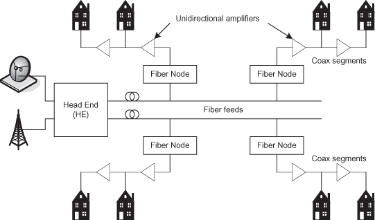
In the above network, the HE acquires video content through standard satellite, terrestrial over-the-air, or other direct feeds. This is then mixed with local content and modulated in analog form to be transmitted via the fiber distribution network. Individual fibers terminate at fiber nodes that service a residential area compromising a few hundred to a few thousand residences. The fiber node performs the optical to electrical domain conversion and re-broadcasts the RF analog signal to the coaxial cable segments. Fiber is effectively lossless in the megahertz to gigahertz frequency range; however, coaxial is not, thus requiring amplifiers to ensure that all residences receive the signal with acceptable quality. The HFC network provided a total downstream spectrum of 54–550 MHz for video broadcast.
In order to provide full duplex communication, the HFC was upgraded to support bidirectional communications. The fiber portion of the network can use physically separate strands to support the upstream communication, but a single coaxial segment must accommodate both upstream and downstream signals. Frequency division duplexing separates a frequency band from 5 MHz to 42 MHz for upstream communication. In addition, the coaxial segment amplifiers are upgraded to support bidirectional amplification. In the downstream direction a 6-MHz channel is reserved for data. Using a 64-symbol QAM modulation technique, 30 Mbit/s of bandwidth is available for high-speed data. In the upstream direction, more robust (and lower bandwidth) modulation techniques, such as Quaternary Phase Shift Key (QPSK) and 16-symbol QAM, are used due to the noisy nature of the upstream 5- to 42-MHz frequency range.
Apart for network upgrades, additional equipment is required to enable full duplex communications in a HFC network. Cable modems (CMs) are customer premise equipment that convert digital information (typically Ethernet frames) into modulated RF signals in the upstream direction and convert the RF signal to digital information in the downstream direction. The Cable Modem Termination System (CMTS) located in the HE performs the converse operation. This involves upconverting the 6-MHz channel, combining with the other channels and converting to and from the optical domain. Figure 3.23 illustrates a HFC network that supports digital data transmission.
Figure 3.23. Bidirectional hybrid fiber coaxial network architecture.
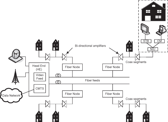
Given that all bandwidth in the HFC is shared, upstream transmissions must be coordinated. The bidirectional amplifiers in the coaxial segments prevent individual CMs from detecting collisions, precluding the use of carrier sense mechanisms such as CSMA/CD. A link layer TDMA mechanism similar in nature to that used in PONs provides collision-free upstream transmission. The HE regularly broadcasts solicitation messages. Newly added stations respond, a ranging procedure determines a latency offset, and the HE allocates a timeslot for the CM transmission.
3.4.2 DOCSIS Standards
The Data Over Cable Service Interface Specification (DOCSIS) standards specify the physical, MAC, and network layer operation for the CM and CMTS. The DOCSIS standards also include specification of security (protecting subscribers data in a shared bandwidth environment) and network management services. DOCSIS 1.0, released in 1997 [43], provided basic Internet connectivity. It supported 64 and 256 QAM downstream modulation schemes and QPSK and 16 QAM modulation for upstream channels. The value of the initial specification was the enforced equipment standardization, which improved interoperability, lowered equipment costs, and resulted in increased deployment. DOCSIS 1.1 completed in 2001 [44] improved security and added QOS capability, allowing MSOs to offer different services over DOCSIS such as voice and gaming. DOCSIS 2.0, introduced in 2002 [45], increased throughput (offering up to 30 Mbit/s upstream and 50 Mbit/s downstream) and provided a greater option of QAM modulation schemes for upstream channels. The latest version of DOCSIS (version 3.0) [39–42] provides channel bonding to increase upstream and downstream bandwidth in order to compete with VDSL/VDLS2 and FTTx networks. With bonding of four channels, 120-Mbit/s upstream and 160-Mbit/s downstream bandwidths are possible. Higher bandwidths are achievable with a greater number of channels. Channel bonding is a logical concatenation of multiple RF channels. In the downstream direction, the multiplexing is at the packet level, with individual packets contained within a single RF channel. In the upstream direction, the packet is “stripped” across the available channels in the group. For example, if a CM has a 1000-byte Ethernet packet to send, it requests a 1000-byte timeslot from the CMTS. In the bonded case, the CMTS responds with grants for segments of the packet across the bonded channels, which may grant a 500-byte timeslot on upstream channel #1, a 200-byte timeslot on upstream channel #2, and a 300-byte timeslot on upstream channel #3. The CM segments the packet into 500-, 200-, and 300-byte fragments and transmits the segments on the three upstream channels. Each segment contains a sequence number and a pointer to allow the CMTS to perform the necessary reassembly, reconstructing the original 1000-byte frame. Channel bonding in DOCSIS 3.0 is backwardly compatible with DOCSIS 1.x/2.0 CMs, allowing a seamless migration to the higher bandwidths. Other notable improvements included in DOCSIS 3.0 are the physically switchable upstream bands, including (a) the standard 5- to 42-MHz and the 5- to 65-MHz and 5- to 85-MHz frequency plans, providing enhanced upstream bandwidth, (b) support for IPv6, QOS support for IP multicast, and subscriber tracking of IP multicast in the CMTS, and (c) enhanced security.
3.4.3 Future Trends
MSOs are keenly aware of the threat posed by FTTH architectures being deployed by telcos. FTTH networks have the advantage of having separate wavelengths for video broadcast (1550 nm) and upstream/downstream (1310/1490 nm) data. The ability for the MSO to deliver similar bandwidth services requires further evolution of the HFC network. MSOs are aggressively pursuing the following evolutionary enhancements:
- Analog bandwidth reclamation reduces the number of TV channels available in the analog band. These are the channels that can be demodulated and received using the tuner built into most television sets. Analog reclamation requires digital encoding and compression of the video signal into a MPEG-4 transport. Decoding requires a customer premise set-top box or equivalent digital decoder function integrated into the television.
- Switched digital video (SDV) moves from a broadcast distribution to a selective multicast distribution model. In SDV, only channels that are being watched are delivered to a group of subscribers (known as a service group).
- Increasing the available spectrum of the plant. The spectrum available in the HFC has been progressively increased from 550 MHz to 750 MHz and presently 860 MHz. Activities are underway that increase this to 1002 MHz (1.002 GHz).
- Simplification of the frequency band plan by consolidating all specialty services, such as digital standard definition TV, video on demand, and high-speed Internet access into a single wide-band (>200 MHz) channel and delivering these services over a consolidated IP transport. Such an architecture will require sophisticated IP layer traffic management capabilities in the CMTS and CM to ensure that services are delivered with the required QOS.
Hybrid fiber coaxial networks and the MSOs that operate them have an incumbent position in the marketplace, delivering the video services of today into many households worldwide. Nevertheless, they are being forced to upgrade their networks in order to offer the raw bandwidths and services promised by next-generation telco networks. Given the financial imperative to survive and compete, HFC networks will continue to be an important aspect of wireline access networks, providing high bandwidth and rich services to many subscribers.
3.5 SUMMARY
Despite their technical differences, wireline access networks have evolved from a physical layer connection for a single service, to become a sophisticated multiservice network in which all traffic, including voice and video, use the Internet Protocol as a converged transport layer. In order to support this evolution, the wireline access networks have focused on increasing the physical layer bandwidth available to subscribers and increasing network intelligence, ensuring that each application or service, when transported over IP, receives the required quality of service necessary to meet the user’s expectations. The next-generation broadband wireline access network will deliver hundreds of megabits and potentially gigabits of bandwidth into each home and business. The availability of this bandwidth will enable services and applications not possible or simply not even envisaged today.
Notes
1 Exact frequency usage is dependent on the type of installed hardware and local deployment conditions.
2 Quadrature carriers are sinusoid waves that are out of phase by 90 °.
3 Also known as a optical network terminal (ONT) in ITU terminology.
REFERENCES
1. US Patent and Trade Mark Office, Patent # 244,426, A. G. Bell, July 19, 1881.
2. Chris Hellberg et al., Broadband Network Architectures: Designing and Deploying Triple Play Services, Prentice-Hall, 2007.
3. J. Cioffi et al., CuPON: The copper alternative to PON 100 Gb/s DSL networks, IEEE Commun. Mag., Vol. 45, No. 6, pp. 132–139, June 2007.
4. D. Waring, J. Lechleider, and T. Hsing, Digital subscriber line technology facilitates a graceful transition from copper to fiber, IEEE Commun. Mag., Vol. 29, No. 3, pp. 96–104, March 1991.
5. J. Cioffi and G. Ginis, Vectored transmission for digital subscriber line systems, IEEE JSAC Special Issue on Twisted Pair Transmissions, Vol. 20, No. 5, pp. 1085–1104, March 2001.
6. ITU-T, ITU-T Recommendation G.992.2: Single-Pair High-Speed Digital Subscriber Line (SHDSL) Transceivers, ITU-T, December 2003.
7. ITU-T, ITU-T Recommendation G.992.1: Asymmetric Digital Subscriber Line (ADSL) Transceivers, July 1999.
8. ITU-T, ITU-T Recommendation G.992.3: Asymmetric Digital Subscriber Line Transceivers 2 (ADSL2), January 2005.
9. ITU-T, ITU-T Recommendation G.992.5: Asymmetric Digital Subscriber Line (ADSL) Transceivers—Extended Bandwidth ADSL2 (ADSL2+), January 2009.
10. ITU-T, ITU-T Recommendation G.993.1: Very High Speed Digital Subscriber Line Transceivers, June 2004.
11. ITU-T, ITU-T Recommendation G.993.2: Very High Speed Digital Subscriber Line Transceivers 2 (VDSL2), February 2006.
12. Broadband Forum, DSL Technology Evolution—ADSL2/ADSL2plus/ADSL-RE/VDSL2, http://www.broadband-forum.org/downloads/About_DSL.pdf.
13. Broadband Forum, www.broadband-forum.com.
14. Broadband Forum, Technical Report TR-101, Migration to Ethernet-Based DSL Aggregation, April 2006.
15. IETF, RFC 2516—A Method for Transmitting PPP Over Ethernet (PPPoE), February 1999.
16. IETF, RFC 2661—Layer Two Tunneling Protocol “L2TP,” August 1999.
17. Telenor Group, dynamic spectrum management—A methodology for providing significantly higher broadband capacity to the users, Telektronikk, No. 4, pp. 126–137, 2004.
18. L Hutcheson, FTTx: Current status and the future, IEEE Commun. Mag., July 2008.
19. ITU-T, ITU-T Recommendation G.983.1: Broadband Optical Access Systems Based on Passive Optical Networks (PON), January 2005.
20. ITU-T, ITU-T Recommendation G. 984.1: Gigabit-Capable Passive Optical Networks (GPON): General Characteristics, March 2003.
21. ITU-T, ITU-T Recommendation G.984.2: Gigabit-Capable Passive Optical Networks (GPON): Physical Media Dependent (PMD) Layer Specification, March 2003.
22. ITU-T, ITU-T Recommendation G. 984.3: Gigabit-Capable Passive Optical Networks (GPON): Transmission Convergence Layer Specification, February 2004.
23. ITU-T, ITU-T Recommendation G. 984.4: Gigabit-Capable Passive Optical Networks (GPON): ONT Management and Control Interface Specification, June 2004.
24. IEEE, IEEE 802.3 Local and Metropolitan Area Networks—Specific Requirements, Part 3: Carrier Sense Multiple Access with Collision Detection (CSMA/CD) Access Method and Physical Layer Specifications, December 2005.
25. IEEE P802.3av task force (http://www.ieee802.org/3/av/).
26. IEEE, Ethernet PON (EPON) and the PAR + 5 Criteria, May 2001, www.ieee802.org/3/efm/public/may01/pesavento_1_0501.pdf.
27. G. Kramer, Ethernet Passive Optical Networks, McGraw-Hill, New York, 2005.
28. Y. Luo et al., Resource management for broadband access over time-division multiplexed passive optical networks, IEEE Network, Vol. 21, No. 5, pp. 20–27, September/October 2007.
29. J. Angelopoulos et al., Efficient transport of packets with QoS in an FSAN-aligned GPON, IEEE Commun. Mag., Vol. 42, No. 2, pp. 92–98, February 2004.
30. M. McGarry, M. Maier, and M. Reisslein, Ethernet PONs: A survey of dynamic bandwidth allocation (DBA) algorithms, IEEE Optical Commun. Mag., Special Supplement Optical Communications, Vol. 42, No. 8, pp. 8–15, August 2004.
31. PMC-Sierra Inc. PAS6301 device, www.pmc-sierra.com.
32. Teknovus Inc. TK3701 device, www.teknovus.com.
33. Full Service Access Network (FSAN), http://www.fsanweb.org/.
34. H. Ueda et al., Deployment status and common technical specifications for a B-PON system, IEEE Commun. Mag., Vol. 39, No. 12, pp. 134–141, December 2001.
35. ITU-T, ITU-T Recommendation, G.7041: Generic Framing Procedure (GFP), February 2003.
36. W. Leland, M. Taqqu, W. Willinger, and D. Wilson, On the self-similar nature of Ethernet traffic (extended version), IEEE/ACM Trans. Networking, Vol. 2, No. 1, pp. 1–15, February 1994.
37. ITU-T, ITU-T Recommendation, G.114: One-Way Transmission Time, May 2003.
38. K. Grobe and J.-P. Elbers, PON in adolescence: From TDMA to WDM-PON, IEEE Commun. Mag., Vol. 46, No. 1, pp. 26–34, January 2008.
39. CableLabs, Data-over-cable service interface specifications, cable modem to customer premise equipment, interface specification, CM-SP-CMCIv3.0-I01-080320, March 2008.
40. CableLabs, Data over cable service interface specifications, DOCSIS 3.0, physical layer specification, CM-SP-PHYv3.0-I08-090121, January 2009.
41. CableLabs, Data-over-cable service interface specifications, DOCSIS 3.0, MAC and upper layer protocols interface specification, CM-SP-MULPIv3.0-I09-090121, January 2009.
42. CableLabs, Data-over-cable service interface specifications, DOCSIS 3.0, security specification CM-SP-SECv3.0-I09-090121, January 2009.
43. CableLabs, DOCSIS 1.0, http://www.cablemodem.com/specifications/specifications10.html.
44. CableLabs, DOCSIS 1.1, http://www.cablemodem.com/specifications/specifications11.html.
45. CableLabs, DOCSIS 2.0, http://www.cablemodem.com/specifications/specifications20.html.