
Chapter 8: Getting Comfortable with the OSPF and IS-IS Protocols
In This Chapter
![]() Configuring common options for the OSPF and IS-IS protocols
Configuring common options for the OSPF and IS-IS protocols
![]() Managing the OSPF and IS-IS protocols with troubleshooting tools
Managing the OSPF and IS-IS protocols with troubleshooting tools
In this chapter, you see a couple of link-state protocols: OSPF (Open Shortest Path First) and IS-IS, which I first discuss in Book IV, Chapter 1. Although in general, link-state protocols all work in the same manner, each is markedly unique to a degree in how they actually carry out their routing. IS-IS has found a home with service providers, and you will not likely implement it on your internal network, whereas OSPF is a popular Interior Gateway Protocol (IGP) that has been implemented on many internal networks. As with other protocols you may have looked at in this minibook in the IGP category, any of them will make a good choice. Using these protocols is easy and straightforward, so you may want to start considering them before your network grows to a point where static routing becomes cumbersome.
As you read this chapter, you will find out how to configure and implement the OSPF and IS-IS protocols, and you will see the main commands you will use to effectively troubleshoot these protocols.
Open Shortest Path First (OSPF)
Because OSPF is an open standard protocol, many people have contributed to its design and thousands upon thousands of people have reviewed it. In this section, I want to point out some functional components of this IGP and its use in your networks.
Getting comfortable with OSPF basics
Because every IGP behaves slightly differently from other IGPs, you should be familiar with a few OSPF terms that are used with the protocol before jumping into the configuration commands. This section attempts to clarify the major terms and concepts you should be familiar with.
OSPF as a link-state protocol
In link-state protocols, the link part of the protocol is the interface on the router, while the state is how it relates to its neighbors, which would include its address and network information. Before you get started, check out this short list of terms used in this section:
• Link State Advertisement (LSA): A simple update on a router’s link status, so one will be sent when a link is connected, disconnected, or otherwise changed
• Topological database: A table in the router’s memory that contains link information about all known routers (see Chapter 6 of this minibook)
• SPF algorithm: A mathematical calculation that uses the Dijkstra algorithm (named after a Dutch mathematician) to determine the shortest path to destinations and that has been heavily applied to computer networks
• SPF tree: A listing all of the routes to any destination with an order of preference
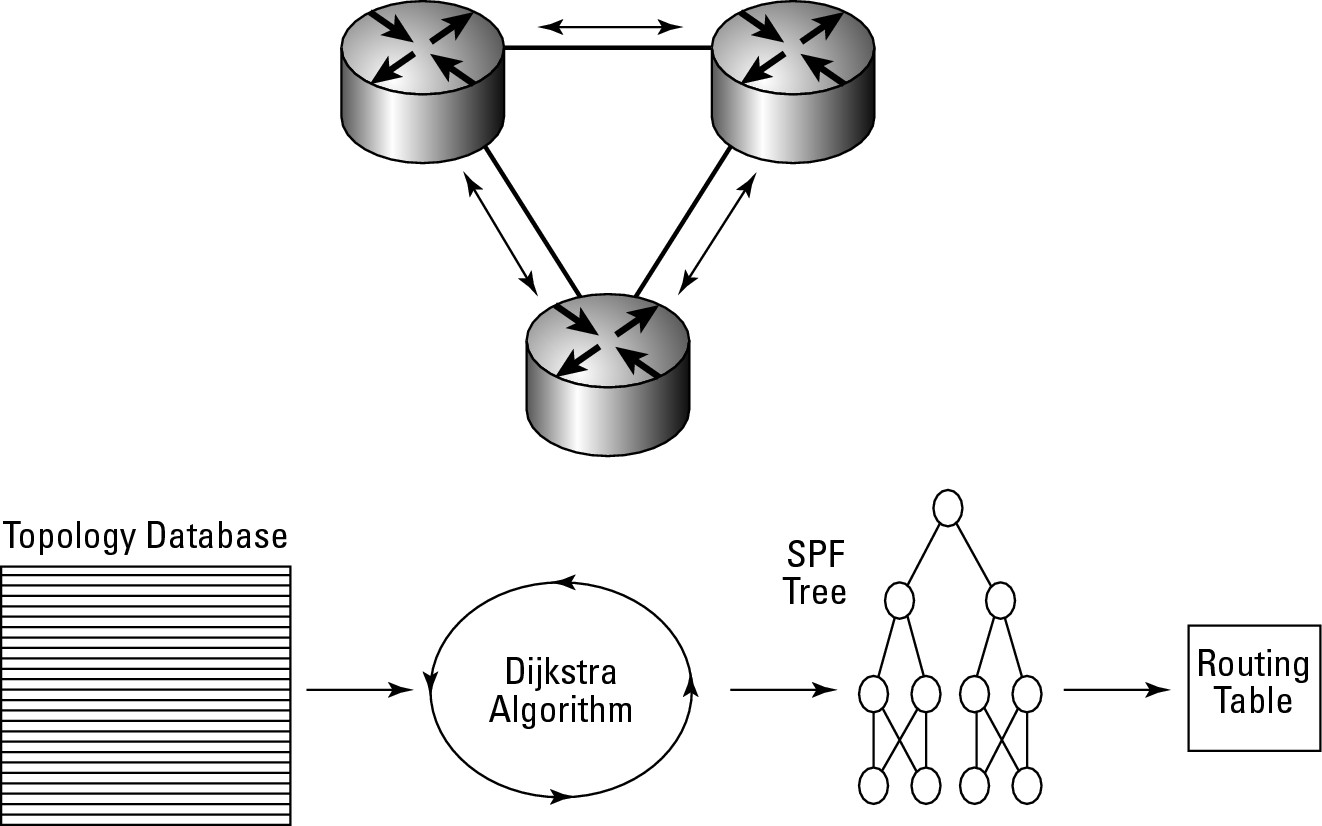
Each router that has been configured for an OSPF area sends out a Link State Advertisement (LSA) at regular intervals. All of this link-state information is stored in a topological database, after which an SPF algorithm is applied to the data in the database. (You find out how to retrieve information from these databases in the section “Troubleshooting OSPF,” later in this chapter.) This process generates an SPF tree listing all of the routes to any destination with an order of preference. The preferred order is then stored in the routing table, giving the router the best routing choices to those destinations. Figure 8-1 illustrates this process:
1. Routers in exchange link-state data start the process.
2. Each router stores the link-state information in memory using a structure named the topology table or topology database.
3. The router processes all data in the topology table and makes use of the Dijkstra algorithm to determine all routes to all networks, as well as the least-cost routes.
4. All this information is stored in the SFP tree, identifying preferred and secondary routes.
5. The routing information is propagated to the routing table.
Figure 8-1: Basics of the OSPF process.
OSPF packet types
OSPF works with a few different types of packets to convey information to surrounding routers.
• Hello packet: Exchanges information about neighbors with each other.
• Database Description packet: Elects a version of the database to be used.
• Link-state request packet: Requests a specific LSA from a neighbor.
• Link-state update packet: Sends an entire LSA to a neighbor who has requested an update.
• Link-state acknowledge packet: Acknowledges the receipt of a link-state update packet.
![]() The default interval for sending LSA updates is 30 minutes, with a 4-minute random offset to prevent all routers from sending at the same time. This interval does not mean that when a change occurs on an interface, it takes up to 30 minutes to start the replication process. Rather, changes in interface status or configuration are sent out immediately. The 30-minute interval is used to refresh data that already exists on other routers. Because a router expects to receive updates every 30 minutes, you may be wondering what happens if an update does not show up on schedule. If an update is not received within four intervals (120 minutes), the router is aged out of the topology database. This might happen if something unexpected happens to the router, such as a power supply failure or becoming unplugged.
The default interval for sending LSA updates is 30 minutes, with a 4-minute random offset to prevent all routers from sending at the same time. This interval does not mean that when a change occurs on an interface, it takes up to 30 minutes to start the replication process. Rather, changes in interface status or configuration are sent out immediately. The 30-minute interval is used to refresh data that already exists on other routers. Because a router expects to receive updates every 30 minutes, you may be wondering what happens if an update does not show up on schedule. If an update is not received within four intervals (120 minutes), the router is aged out of the topology database. This might happen if something unexpected happens to the router, such as a power supply failure or becoming unplugged.
All routers that share a common area identifier (or area ID) receive the LSA data, not just routers on the same data link.
Knowing areas and Autonomous Systems
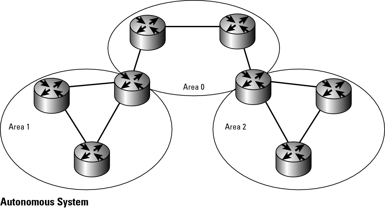
When designing your OSPF network, the two main factors you work with are areas and how they fit within an AS. Areas are functional areas of your network, perhaps a building or the floor of a building, and Autonomous Systems are collections of areas, which typically are your entire network.
The overall OSPF network is divided into groups called areas, whereas all routers in an organization are probably part of a single AS, as shown in Figure 8-2. The area is defined as a logical division of the AS, broken up into contiguous sections of the IP network. In other words, you break the area along groups of subnets that can be grouped together with a single routing entry. In a typical large network, an area may consist of 30 to 40 routers.
Figure 8-2:
OSPF networks are Autonomous Systems that are broken into areas.
The Hello packet
The faster, more regular packet of OSPF management packets, is the multicast OSPF Hello packet, which goes to the address 224.0.0.5. The Hello packet is the mechanism that creates the neighbor relationships between routers. By default, these packets go out every ten seconds on broadcast media, alerting surrounding neighbors that the router is still up and running. The dead interval (the time when a neighbor is possibly down) for Hello information is four times the Hello interval, so if a router fails to send four sets of Hello packets, it will be flagged as unavailable and its routes will be suspect. It will later be removed when four update intervals have passed.
When OSPF Hello packets are sent out, they contain several pieces of information. Here is a list of the key items:
• Router ID: Found in the OSPF header, the Router ID is a 32-bit numeric identifier that, by default, is the highest IP address among all the available interfaces. By implementing a loopback interface, you can exercise some control over the Router ID. You can also use the router-id configuration parameter (discussed in the section “Keeping track of router IDs,” later in this chapter) to set the Router ID to a preferred value.
• Neighbors: At the end of the Hello packet is a list of all known neighbor routers, which allows each neighbor to know about all other neighbors.
• Area ID: Neighbors must share a common segment, and their interfaces must belong to the same OSPF area on that segment. They must also share the same subnet and mask.
• Router priority: An 8-bit number for priority, used to select Designated Router (DR) and Backup Designated Router (BDR).
• DR and BDR IP addresses: The addresses of both the DR and BDR.
• Authentication password: The authentication password. Performing authentication is an optional security feature with the OSPF protocol.
• Stub area flag: Reduces updates by individually routing them with a default route.
Checking out the base cost
After the router gathers all the information, it calculates a base cost for each route. The cost is calculated with this formula:
Cost = reference bandwidth / interface bandwidth in bps
The reference bandwidth is the same as Fast Ethernet, which is 100,000,000. Fast Ethernet links always have a cost of 1. If you are calculating the cost of a Gigabit Ethernet link, you use 100,000,000/1,000,000,000, which gives you 0.1. The cost of an Ethernet link is 100,000,000/10,000,000, which gives you 10; the cost of a T1 link is 100,000,000/1,544,000, which gives you a cost of 64. The slower the link, the higher the cost, and the less it is preferred. The lowest cost link will always be preferred.
Configuring OSPF
Initially enabling OSPF requires only two commands:
• router ospf process-id: This command enables the OSPF process and then you will require a network command for each network for which you will be routing. The router command is the two-part command, where the process-id is a unique and arbitrary local ID for the OSPF process. OSPF is unlike other routing protocols that identify which routers belong to a group; here the router identifies the copy of OSPF that is running, because you can have more than one OSPF process running, allowing your router to participate in different AS groups.
• network address wildcard-mask area area-id: This command is similar to other network commands that identify the network by the IP address or the IP network appropriate for each interface for which you will be routing. With OSPF, the main difference is that you include both a wildcard mask to change the range of addresses you are working with and the area ID of the OSPF area to which the address belongs.
Router2>enable
Password:
Router2#configure terminal
Enter configuration commands, one per line. End with CNTL/Z.
Router2(config)#router ospf 100
Router2(config-router)#network 192.168.1.240 0.0.0.0 area 0
Router2(config-router)#network 192.168.5.1 0.0.0.0 area 0
Router2(config-router)#exit
Router2(config)#exit
Working with wildcard masks
When working with wildcard masks (covered in detail in Book VI, Chapter 3), Cisco recommends sticking to the interface address with all zeros (0) in the mask. If you want to deviate from this method, breaking the mask at 8-bit boundaries is the next recommendation because it reduces the chance of making errors.
With the exception of the global wildcard mask of all zeros — which is special — there is the matching rule. With the matching rule, where there is a binary zero in the mask, the mask requires a match, but where there is a binary 1 in the mask, the mask does not care about the address. Figure 8-3 shows a sample on which I walk you through the use of wildcard masks which will be valid in different situations.
![]() Wildcard masks work differently than subnet masks do. Subnet masks remove the host section of an address, leaving you with a network ID, whereas wildcard masks identify the portions of an address that need to match. If you reverse the bits and perform the logical AND process (the AND process is covered in Book II, Chapter 3), you end up matching the same network.
Wildcard masks work differently than subnet masks do. Subnet masks remove the host section of an address, leaving you with a network ID, whereas wildcard masks identify the portions of an address that need to match. If you reverse the bits and perform the logical AND process (the AND process is covered in Book II, Chapter 3), you end up matching the same network.
Figure 8-3: A sample OSPF network.
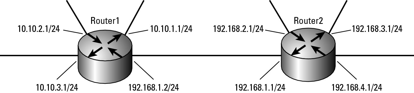
If the figure matches the scope of your entire network, and Router1 can use these two network lines:
network 192.168.1.0 0.0.0.255 area 192
network 10.0.0.0 0.255.255.255 area 10
Whereas Router2, which has no 10.0.0.0/8 network segments, can use this network command:
network 192.168.0.0 0.0.255.255 area 192
In this example, all networks in the 10.0.0.0/8 range can be routed through Router1, and Router2 can route all of the 192.168.0.0/16 networks. If you add another router to the network and use an address from the 192.168.0.0/16 or 10.0.0.0/8 network blocks, you may encounter routing issues implementing these wildcard masks. Although you do less typing with the class-based address masks (one network mask, rather than four, for all of Router2), you must do more planning around the network addresses (which you should be doing anyway). So, you can be more limiting in how you assign masks for these network commands. Router1’s commands are as follows:
network 192.168.1.0 0.0.0.255 area 192
network 10.10.0.0 0.0.127.255 area 10
Router2’s network commands are as follows:
network 192.168.1.0 0.0.0.255 area 192
network 192.168.2.0 0.0.127.255 area 192
network 192.168.4.0 0.0.0.255 area 192
In this set of examples, you end up with two big differences. Based on the mask now assigned to the 10.10.0.0/16 network block of Router1, your router identifies itself as the router from all addresses from 10.10.0.0 through 10.10.3.255, which is fine as long as you do not plan to use 10.10.0.0/24 on another area of your network. On Router2, the router now routes for 192.168.1.0 through 192.168.4.255. If you were not using the network segments on your network, you would identify it as the router for 192.168.0.0 through 192.168.7.255 with this single command:
Network 192.168.0.0 0.0.63.255 area 192
![]() Although you can reduce your typing a little bit by using wildcard masks, doing so can cause a lot of confusion, so using the interface addresses will make life easier.
Although you can reduce your typing a little bit by using wildcard masks, doing so can cause a lot of confusion, so using the interface addresses will make life easier.
Keeping track of router IDs
When it comes to troubleshooting on your network, keeping track of the various Router IDs that show up in your raw network data can be confusing. Also, when an interface goes down, the Router’s ID may change, further complicating matters.
You can assign a Router ID either by using the router-id command in Router Configuration mode or by assigning an address to a loopback interface that is higher than any other address on any other interface on your router. The loopback interface should never go down, so using it is a good choice and is the method that I will explain.
In the private address range, 192.168.255.0/24 represents the highest addresses you will likely ever use on your network. If you have fewer than 254 routers on your network, this range is ideal, but if you can, you should keep the 192.168.254.0/24 range available. By keeping the second range available, you will have another 254 addresses you will be able to assign as Router IDs. The following code enables a loopback interface numbered 0 and assigns an address to the interface.
Loopback
Router2>enable
Password:
Router2#configure terminal
Enter configuration commands, one per line. End with CNTL/Z.
Router2(config)#interface loopback 0
Router2(config-if)#ip address 192.168.255.254 255.255.255.0
Router2(config-if)#exit
Router2(config)#router ospf 100
Router2(config-router)#network 192.168.255.254 0.0.0.0 area 0
Router2(config-router)#exit
Router2(config)#exit
![]() The only item you might not know about in the preceding code snippet is advertising the network of your Router IDs in the OSPF routing interface. The command network
The only item you might not know about in the preceding code snippet is advertising the network of your Router IDs in the OSPF routing interface. The command network 192.168.255.254 0.0.0.0 area 0 tells OSPF that the 192.168.255.0/24 network is a routable network ID on the network. This item is not required. By advertising the router to this network, you can use this address to connect to the router for remote administration. The drawback is that before advertising this network, you would have been able to also use this address block on your network.
![]() Although I said that OSPF always uses the highest configured address of any interface as its Router ID, it actually always prefer a loopback interface over any other type of interface. With that said, when you configure multiple loopback interfaces, 192.168.254.0/24 still represents a good address block for assigning addresses.
Although I said that OSPF always uses the highest configured address of any interface as its Router ID, it actually always prefer a loopback interface over any other type of interface. With that said, when you configure multiple loopback interfaces, 192.168.254.0/24 still represents a good address block for assigning addresses.
When there are multiple paths to a destination, OSPF automatically performs equal cost-load balancing. It supports up to 16 paths to the destination, but by default only operates with four paths. You can change this behavior by using the maximum-paths command as follows:
Router2>enable
Password:
Router2#configure terminal
Enter configuration commands, one per line. End with CNTL/Z.
Router2(config-router)#maximum-paths 10
Router2(config-router)#exit
Router2(config)#exit
Another way to influence the route selection is to manually adjust the cost of a link. In the earlier section “Checking out the base cost,” you might have read that the cost of a link is based on the speed of the link, with FastEthernet being a 1 and faster or slower links being based off that link speed. To manually influence the cost, use Interface Configuration mode and the ip ospf cost command, as shown here (where the link cost is set to 5):
Router2>enable
Password:
Router2#configure terminal
Enter configuration commands, one per line. End with CNTL/Z.
Router2(config-if)ip ospf cost 5
Router2(config-if)#exit
Router2(config)#exit
Troubleshooting OSPF
As you probably realize by now, the best way to troubleshoot is to gather information. The first source of information is the show command. In this section, you will take a look at the most relevant options to be used with the show command to assist in your information gathering and troubleshooting of OSPF.
Viewing routes in the routing table
After OSPF is enabled, what do the routes look like in the routing table? You can use the show ip route command, which shows the standard internal OSPF routes listed with a letter O, inter-area routes listed with IA, and external routes listed with N1 or N2.
Router2>enable
Password:
Router2#show ip route
Codes: C - connected, S - static, R - RIP, M - mobile, B - BGP
D - EIGRP, EX - EIGRP external, O - OSPF, IA - OSPF inter area
N1 - OSPF NSSA external type 1, N2 - OSPF NSSA external type 2
E1 - OSPF external type 1, E2 - OSPF external type 2
i - IS-IS, su - IS-IS summary, L1 - IS-IS level-1, L2 - IS-IS level-2
ia - IS-IS inter area, * - candidate default, U - per-user static route
o - ODR, P - periodic downloaded static route
Gateway of last resort is not set
O 192.168.10.0/24 [110/11] via 192.168.1.1, 00:01:01, FastEthernet0/0
C 192.168.5.0/24 is directly connected, FastEthernet0/1
C 192.168.255.0/24 is directly connected, Loopback0
C 192.168.1.0/24 is directly connected, FastEthernet0/0
S 192.168.3.0/24 [1/0] via 192.168.1.1
To be more specific about the information you are requesting, you can request information for a specific route. The results show where you have read about the route and read exactly why this route is preferred over other routes that are similar to that destination.
Router2>enable
Password:
Router2#show ip route 192.168.10.0
Routing entry for 192.168.10.0/24
Known via “ospf 100”, distance 110, metric 11, type intra area
Last update from 192.168.1.1 on FastEthernet0/0, 00:15:25 ago
Routing Descriptor Blocks:
* 192.168.1.1, from 192.168.10.1, 00:15:25 ago, via FastEthernet0/0
Route metric is 11, traffic share count is 1
Viewing your IP protocols
The show ip protocols command (mentioned in the previous section “Viewing routes in the routing table”), will show you the OSPF process number and basic information about the OSPF protocol. The following list identifies the key pieces of information that you will see with the show ip protocols command:
• Filters you configured for the protocol
• The Router ID (note that in this case the Router ID is still set to the Fast Ethernet interface)
• Areas that the router routes
• Number of equal paths for which OSPF will load balance
• Local networks that OSPF has configured with areas
• Neighbors with their last update and administrative distance
The following output shows the particular settings for the OSPF protocol:
Router2>enable
Password:
Router2#show ip protocols
Routing Protocol is “ospf 100”
Outgoing update filter list for all interfaces is not set
Incoming update filter list for all interfaces is not set
Router ID 192.168.5.1
Number of areas in this router is 1. 1 normal 0 stub 0 nssa
Maximum path: 4
Routing for Networks:
192.168.1.240 0.0.0.0 area 0
192.168.255.254 0.0.0.0 area 0
Routing Information Sources:
Gateway Distance Last Update
192.168.5.1 110 00:02:50
Distance: (default is 110)
Viewing options for the show ip ospf command
Many options are available for the show ip ospf command. These options are listed in the following output, followed by a discussion of a few of the key ones. Bear in mind that the results for some commands may lead you to seek specific information in other areas. For example, if you do not see neighbors, you may want to investigate why they are not showing up.
Router2>enable
Password:
Router2#show ip ospf ?
<1-65535> Process ID number
border-routers Border and Boundary Router Information
database Database summary
flood-list Link state flood list
interface Interface information
mpls MPLS related information
neighbor Neighbor list
request-list Link state request list
retransmission-list Link state retransmission list
sham-links Sham link information
statistics Various OSPF Statistics
summary-address Summary-address redistribution Information
timers OSPF timers information
virtual-links Virtual link information
| Output modifiers
<cr>
The first key command is show ip ospf, which shows basic configuration information related to the protocol and its operation. In this case, you see that the Process ID is 100, the router is only configured for one area, and the SPF algorithm has run twice on one LSA.
Router2>enable
Password:
Router2#show ip ospf
Routing Process “ospf 100” with ID 192.168.5.1
Supports only single TOS(TOS0) routes
Supports opaque LSA
Supports Link-local Signaling (LLS)
Initial SPF schedule delay 5000 msecs
Minimum hold time between two consecutive SPFs 10000 msecs
Maximum wait time between two consecutive SPFs 10000 msecs
Incremental-SPF disabled
Minimum LSA interval 5 secs
Minimum LSA arrival 1000 msecs
LSA group pacing timer 240 secs
Interface flood pacing timer 33 msecs
Retransmission pacing timer 66 msecs
Number of external LSA 0. Checksum Sum 0x000000
Number of opaque AS LSA 0. Checksum Sum 0x000000
Number of DCbitless external and opaque AS LSA 0
Number of DoNotAge external and opaque AS LSA 0
Number of areas in this router is 1. 1 normal 0 stub 0 nssa
External flood list length 0
Area BACKBONE(0) (Inactive)
Number of interfaces in this area is 2 (1 loopback)
Area has no authentication
SPF algorithm last executed 00:06:37.652 ago
SPF algorithm executed 2 times
Area ranges are
Number of LSA 1. Checksum Sum 0x006FFE
Number of opaque link LSA 0. Checksum Sum 0x000000
Number of DCbitless LSA 0
Number of indication LSA 0
Number of DoNotAge LSA 0
Flood list length 0
Viewing information about interfaces
With show ip ospf interface, you can get more detail about the specific interfaces being used for OSPF. At this point, the loopback interface is configured, the timer intervals are still set to default values, a DR and BDR are selected, and 192.168.10.1 is the only neighbor.
Router2>enable
Password:
Router2#show ip ospf interface
Loopback0 is up, line protocol is up
Internet Address 192.168.255.254/24, Area 0
Process ID 100, Router ID 192.168.5.1, Network Type LOOPBACK, Cost: 1
Loopback interface is treated as a stub Host
FastEthernet0/0 is up, line protocol is up
Internet Address 192.168.1.240/24, Area 0
Process ID 100, Router ID 192.168.5.1, Network Type BROADCAST, Cost: 1
Transmit Delay is 1 sec, State DR, Priority 1
Designated Router (ID) 192.168.5.1, Interface address 192.168.1.240
Backup Designated router (ID) 192.168.10.1, Interface address 192.168.1.1
Timer intervals configured, Hello 10, Dead 40, Wait 40, Retransmit 5
oob-resync timeout 40
Hello due in 00:00:07
Index 1/1, flood queue length 0
Next 0x0(0)/0x0(0)
Last flood scan length is 1, maximum is 1
Last flood scan time is 0 msec, maximum is 0 msec
Neighbor Count is 1, Adjacent neighbor count is 1
Adjacent with neighbor 192.168.10.1 (Backup Designated Router)
Suppress hello for 0 neighbor(s)
Viewing detailed info about neighbors
To view detailed information about the neighbors that are seen, you use the neighbor option. Here, you see that the neighbor is a Backup Designated Router (BDR) that has fully converged (believes that all routers know the current state of the network). Because the Neighbor ID does not match the neighbor’s IP address, you can guess that it also routes for network 192.168.10.0/24 or that it has a loopback interface configured for that address. My guess is the former because 192.168.10.0/24 does not show up in the list of networks that it is a router for.
Router2>enable
Password:
Router2#show ip ospf neighbor
Neighbor ID Pri State Dead Time Address Interface
192.168.10.1 1 FULL/BDR 00:00:32 192.168.1.1 FastEthernet0/0
You can explore more of the show ip ospf options on your own to become familiar with their output.
Debugging OSPF
Now, it is time to move on to the infamous debug commands that are available to OSPF. As with the show command, the debug command has many options. Because spreading the net too widely can cause a lot of information to sift through, you want to make the scope of the command as narrow as possible. Unlike other debugging commands, there is not a general debug ip ospf, so you are forced to be a little selective.
Router2>enable
Password:
Router2#debug ip ospf ?
adj OSPF adjacency events
database-timer OSPF database timer
events OSPF events
flood OSPF flooding
hello OSPF hello events
lsa-generation OSPF lsa generation
mpls OSPF MPLS
nsf OSPF non-stop forwarding events
packet OSPF packets
retransmission OSPF retransmission events
spf OSPF spf
tree OSPF database tree
Viewing events
The events option is just about the most general option among the available options. The output that follows shows these options:
• The router is sending Hello packets out to the multicast address on one of its network interfaces.
• The router is selected as the Designated Router.
• The router found a route to 192.168.10.0/24 from one of its neighbors.
Router2>enable
Password:
Router2#debug ip ospf events
OSPF events debugging is on
*Mar 18 02:58:36.069: OSPF: Interface FastEthernet0/0 going Up
*Mar 18 02:58:36.069: OSPF: Send hello to 224.0.0.5 area 0 on FastEthernet0/0 from 192.168.1.240
*Mar 18 02:58:46.069: OSPF: Send hello to 224.0.0.5 area 0 on FastEthernet0/0 from 192.168.1.240exit
*Mar 18 02:58:56.069: OSPF: Send hello to 224.0.0.5 area 0 on FastEthernet0/0 from 192.168.1.240
*Mar 18 02:59:06.069: OSPF: Send hello to 224.0.0.5 area 0 on FastEthernet0/0 from 192.168.1.240
*Mar 18 02:59:16.069: OSPF: end of Wait on interface FastEthernet0/0
*Mar 18 02:59:16.069: OSPF: DR/BDR election on FastEthernet0/0
*Mar 18 02:59:16.069: OSPF: Elect BDR 192.168.5.1
*Mar 18 02:59:16.069: OSPF: Elect DR 192.168.5.1
*Mar 18 02:59:16.069: OSPF: Elect BDR 0.0.0.0
*Mar 18 02:59:16.069: OSPF: Elect DR 192.168.5.1
*Mar 18 02:59:16.069: DR: 192.168.5.1 (Id) BDR: none
*Mar 18 02:59:16.069: OSPF: Send hello to 224.0.0.5 area 0 on FastEthernet0/0 from 192.168.1.240
*Mar 18 03:25:46.084: %OSPF-5-ADJCHG: Process 100, Nbr 192.168.10.1 on FastEthernet0/0 from LOADING to FULL, Loading Done
Router2#no debug ip ospf events
![]() You can discover a great deal from the various
You can discover a great deal from the various debug commands, but the scope of this book does not permit me to go into depth on all of them. However, if you plan to deploy OSPF, viewing information regarding the various commands will be a worthwhile investment.
Intermediate System to Intermediate System (IS-IS)
When comparing IS-IS to OSPF, you see some similarities. Both are link-state protocols and both use the Dijkstra algorithm to calculate the best route through a network. One major difference between the protocols relates to how they operate in the OSI model. IS-IS is a native Layer 3 (network layer) protocol, so it is capable of passing routing information for any routable protocol, and it is not restricted to IP like OSPF and many other routing protocols are. Most other routing protocols required modification in order to support IPv6, whereas because IS-IS is network-protocol neutral, it can support IPv6 right out of the gate.
Regarding the way it supports areas, IS-IS also differs from OSPF in that routers route as Level 1 or intra-area within an area, as Level 2 or inter-area between areas, or as Levels 1–2 when performing both types of routing.
Enabling IS-IS routing
The basic command to enable IS-IS routing is router isis [area tag], where the area tag is either 1, 2, or 1–2. By default, if the area tag is omitted, the first instance of IS-IS uses Level 1–2 and Level 1 for later instances. After specifying the router command, you specify network entity titles on the net statements, which is like specifying the RouterID, the only requirement is that this value be unique across your network. In this case, you use 49.0001.0000.000a.00 as a base for the IDs and specify unique values for each router using 0a.00 and incrementing upward.
Unlike other protocols where you use the network command to identify networks that will be included in routing, with IS-IS, the ip router isis command is issued on each interface for which you want to route for FastEthernet 0/0 and FastEthernet 0/1, as shown here:
Router2>enable
Password:
Router2#configure terminal
Enter configuration commands, one per line. End with CNTL/Z.
Router2(config)#router isis
Router2(config-router)#net ?
XX.XXXX. ... .XXX.XX Network entity title (NET)
Router2(config-router)#net 49.0001.0000.0000.000a.00
Router2(config-router)#exit
Router2(config)#interface FastEthernet 0/0
Router2(config-if)#ip router isis
Router2(config-if)#exit
Router2(config)#interface FastEthernet 0/1
Router2(config-if)#ip router isis
Router2(config-if)#exit
Router2(config)#exit
When viewing the routing table, you see all the IS-IS routes listed with i and another identifier to show whether they are Level 1, Level 2, or inter-area (Level 1–2). You can see in the listing that the network of 192.168.6.0/24 is an IS-IS Level 1 network.
Router2>enable
Password:
Router2#show ip route
Codes: C - connected, S - static, R - RIP, M - mobile, B - BGP
D - EIGRP, EX - EIGRP external, O - OSPF, IA - OSPF inter area
N1 - OSPF NSSA external type 1, N2 - OSPF NSSA external type 2
E1 - OSPF external type 1, E2 - OSPF external type 2
i - IS-IS, su - IS-IS summary, L1 - IS-IS level-1, L2 - IS-IS level-2
ia - IS-IS inter area, * - candidate default, U - per-user static route
o - ODR, P - periodic downloaded static route
Gateway of last resort is not set
C 192.168.5.0/24 is directly connected, FastEthernet0/1
i L1 192.168.6.0/24 [115/20] via 192.168.1.2, FastEthernet0/0
C 192.168.255.0/24 is directly connected, Loopback0
C 192.168.1.0/24 is directly connected, FastEthernet0/0
S 192.168.3.0/24 [1/0] via 192.168.1.1
Checking that IS-IS is running
To ensure that you have IS-IS running on your router, use the ever-popular show ip protocols command. In the following listing, you see the following:
• IS-IS is enabled on the router.
• Maximum equal cost load-balanced routing is 4.
• IS-IS is routing for two interfaces.
• There are two neighbor routes with an administrative distance of the default 115.
Router2>enable
Password:
Router2#show ip protocols
Routing Protocol is “isis”
Invalid after 0 seconds, hold down 0, flushed after 0
Outgoing update filter list for all interfaces is not set
Incoming update filter list for all interfaces is not set
Redistributing: isis
Address Summarization:
None
Maximum path: 4
Routing for Networks:
FastEthernet0/0
FastEthernet0/1
Routing Information Sources:
Gateway Distance Last Update
192.168.1.2 115 00:06:05
192.168.5.2 115 00:05:46
Distance: (default is 115)
Troubleshooting the IS-IS protocol
Once again, you investigate the show and debug commands to see how they can assist you in troubleshooting issues with the IS-IS protocol.
Viewing the show options
To start, here are the different options available in the show command:
Router2>enable
Password:
Router2#show isis ?
* All IS-IS address families
database IS-IS link state database
hostname IS-IS Dynamic hostname mapping
ipv6 IS-IS IPv6
lsp-log IS-IS LSP log
mesh-groups IS-IS mesh groups
mpls IS-IS MPLS
neighbors IS-IS neighbors
rib ISIS local RIB information
route IS-IS level-1 routing table
spf-log IS-IS SPF log
topology IS-IS paths to Intermediate Systems
Among these options are several with useful information, most notably database, neighbors, route, and topology. Because you may have read about similar neighbor and route commands in Chapter 7 of this minibook, I now show you the output of the topology command. Notice that it includes both Level 1 and Level 2 routers, which both of the referenced routers are members of, because they were created with the default options on router isis. Router2 sees that the router Router1 is found on interface Fa0/0. So, with the topology command, you can see neighbors and further, whereas the neighbors command would only show adjacent routers.
Router2>enable
Password:
Router2#show isis topology
IS-IS paths to level-1 routers
System Id Metric Next-Hop Interface SNPA
Router2 --
Router1 10 Router1 Fa0/0 0017.e0c9.b7b0
IS-IS paths to level-2 routers
System Id Metric Next-Hop Interface SNPA
Router2 --
Router1 10 Router1 Fa0/0 0017.e0c9.b7b0
Looking at debug options
Finally, you look at the debug options, which are similar to the OSPF debug commands shown earlier in this chapter. Depending on the types of problems you are experiencing, you may want to focus on different parts of the IS-IS protocol, such as adj-packets, protocol-errors, or spf-statistics.
Router2>enable
Password:
Router2#debug isis ?
adj-packets IS-IS Adjacency related packets
authentication IS-IS packet authentication
checksum-errors IS-IS LSP checksum errors
local-updates IS-IS local update packets
mpls IS-IS MPLS
nsf IS-IS Non-Stop Forwarding
protocol-errors IS-IS LSP protocol errors
rib IS-IS IP Routing Information Base
snp-packets IS-IS CSNP/PSNP packets
spf-events IS-IS Shortest Path First Events
spf-statistics IS-IS SPF Timing and Statistic Data
spf-triggers IS-IS SPF triggering events
update-packets IS-IS Update related packets