
Chapter 2: Planning Your WLAN
In This Chapter
![]() Identifying the basic parameters to configure a wireless network
Identifying the basic parameters to configure a wireless network
![]() Identifying common issues with implementing wireless networks
Identifying common issues with implementing wireless networks
![]() Identifying and describing the purpose of the components in a small wireless network
Identifying and describing the purpose of the components in a small wireless network
When working with wireless LANs, you need to know their operating modes as well as how to lay out access points (APs) to allow maximum coverage while reducing internal conflicts.
In this chapter, I show you how to set up your clients in either Ad Hoc or Infrastructure modes and the benefits of each mode, elements that make up a wireless network, and what configuration parameters you need to be aware of; you see the actual configuration in upcoming chapters. Finally, I show you how to design and lay out your access points on your network to provide ideal RF coverage. With this information, you will be well on your way to deploying a wireless network.
Setting Your Operation Mode
When you are working with a traditional wired network, you connect your computer to a network switch to interconnect all devices on your network; or you use crossover network cables to directly connect two computers. In the case of wireless networking, you still have two choices: You can connect two devices directly, or you can connect your devices using a central device, namely a wireless access point. These two methods are:
• Ad Hoc mode for when the devices connect without the aid of an AP. Ad hoc is Latin meaning “for this,” and generally means “for this specific situation.” The term ad hoc is regularly used to describe committees, organizations, or repairs that are thrown together quickly and for one single purpose. In the case of the wireless LAN, it is put together temporarily and without the aid of an AP. When the members of the ad hoc wireless LAN leave the area, the wireless LAN disappears.
• Infrastructure mode for when you use an AP to manage the connection of clients either between each other or with the wired LAN.
Ad Hoc mode
Back when floppy disks were the main method of transferring data between computers, I often encountered groups of users who took over a boardroom for a period of time to work on a project that required a good deal of sharing of documents with only a single printer for the room. Typically, the users did not need resources such as the Internet, because it was not nearly as pervasive then. Shuttling data back and forth on floppies was tedious and difficult (especially when the files exceeded the size of the disk). When the users came to my office and asked me for a better solution than those #@!#@ floppy disks, I would have one which only required a bit of extra work. As a provider of networking services for my users (unless I was one of those in that boardroom), I tossed them some cables and a hub (at the time) and said “Go to it!” because that equipment was enough at the time to put together a rag-tag network on a boardroom conference table. Wires were everywhere with one computer using the parallel port printer and all users sharing a folder from which they worked. This solution was not ideal, but it made the job of printing, sharing, and transferring files much easier and allowed them to complete their project in a shorter time period than if they used floppy disks.
Now fast-forward to today, and the floppies are now USB thumb drives, that boardroom hub is replaced with Ad Hoc mode wireless networks, and those guys do not even have to come in to see me.
Understanding Ad Hoc mode networking
When working with networking in Ad Hoc mode, you are connecting to another device that has the same wireless settings as the settings on your device. The benefit of ad hoc networking is that you do not need to preconfigure your network infrastructure to support a temporary group of users, while the users (or rather their devices) are able to share information among themselves. A sample ad hoc wireless network is shown in Figure 2-1, and it required very little configuration. The ad hoc wireless LAN is created by two or more computers that have configured their wireless LAN settings to be the same. This matching of wireless LAN settings allows the computer to form a direct network connection when they are close enough for the wireless signals to communicate.
In addition to device-to-device connections, you can also use ad hoc networking in wireless mesh devices, in which all devices (APs) connect to the mesh (that being a few devices that are clustered near each other, similar to the ad hoc network illustrated in Figure 2-1), and data will pass from AP to AP through the mesh until it reaches its final destination. The advantage of using this type of technology is that all APs can be provided with rudimentary routing information that allows the AP not only to handle routing changes as needed, but also to determine the best way to pass packets, or to be able to pass packets due to a hardware failure in one of the APs. After a hardware failure, all other APs update their paths for data so that they do not attempt to send data through the failed AP.
Figure 2-1: A sample wireless ad hoc network.
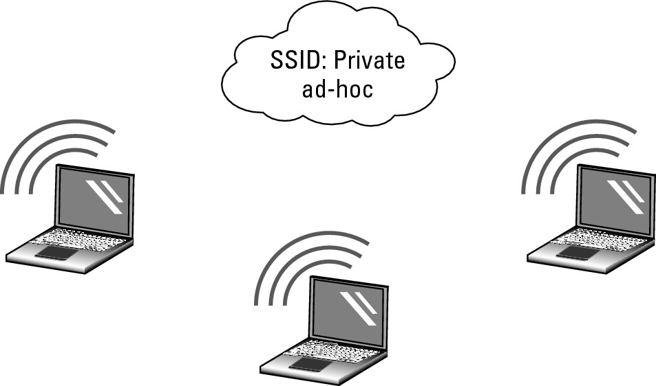
![]() When dealing with Ad Hoc mode WLAN technology, focus on device-to-device connections. The wireless mesh combines ad hoc networking with an additional layer of software to support the mesh communication process.
When dealing with Ad Hoc mode WLAN technology, focus on device-to-device connections. The wireless mesh combines ad hoc networking with an additional layer of software to support the mesh communication process.
Configuring an Ad Hoc mode WLAN
In most cases, when discussing Ad Hoc mode wireless networking, you are dealing with device-to-device connections. These connections are easy enough to set up in Windows with processes described in the following sections.
Configuring an Ad Hoc mode WLAN with Windows 7
If you have a Windows 7 computer (or a Windows Vista computer, which is very similar), you will use a process similar to the following to create and activate your ad hoc network.
1. Click Start and choose Control Panel.
This opens the Control Panel window.
2. Select View Network Status and Tasks.
This opens the Network and Sharing Center window.
3. From the Network and Sharing Center window, select Set Up a New Connection or Network.
The Set Up a Connection or Network dialog box appears.
4. From the Set Up a Connection or Network dialog box, choose Set Up a Wireless Ad Hoc (Computer-to-Computer) Network and click Next; click Next again.
The Set Up an Ad Hoc Network dialog box appears, as shown in Figure 2-2.
Figure 2-2: Setting up the ad hoc networkconfiguration in Windows 7.
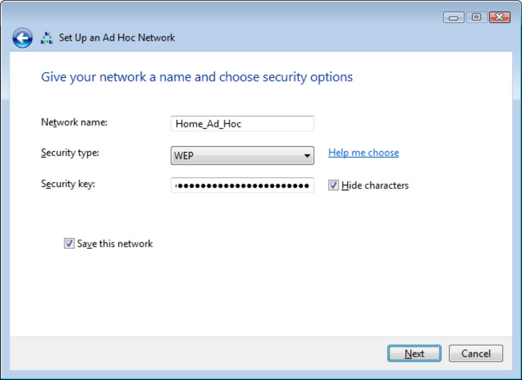
5. In the Set Up an Ad Hoc Network dialog box, provide the following information:
a. Add a network name for your wireless network.
b. Indicate the security type as either WEP or No Authentication.
c. If you chose WEP, provide the security key for the network and optionally select the Hide Characters box.
d. Select Save This Network to keep this network for longer than one session.
6. Click Next to continue.
The confirmation dialog is displayed, showing you the information that you need to provide to other people who will want to connect to your ad hoc network.
7. Click Close.
After the connection is set up, it initially becomes active and remains so until you connect to another network. If you did not choose to save the connection, it will be removed from your wireless configuration at that time and you will need to repeat this process to reactivate an ad hoc network connection.
Configuring an Ad Hoc mode WLAN with Windows XP
In Windows XP, follow these steps to configure an Ad Hoc mode WLAN:
1. Click Start and choose Control Panel from the Start menu.
The Control Panel window opens.
2. From the Control Panel window choose Network and Internet Connections.
The Network and Internet Connections settings are displayed.
3. From the Network and Internet Connections window, choose Network Connections.
The Network Connection dialog box appears.
4. Locate your wireless network card in the dialog box’s list, right-click on it, and then click the Properties.
The Properties dialog for that network card will be displayed.
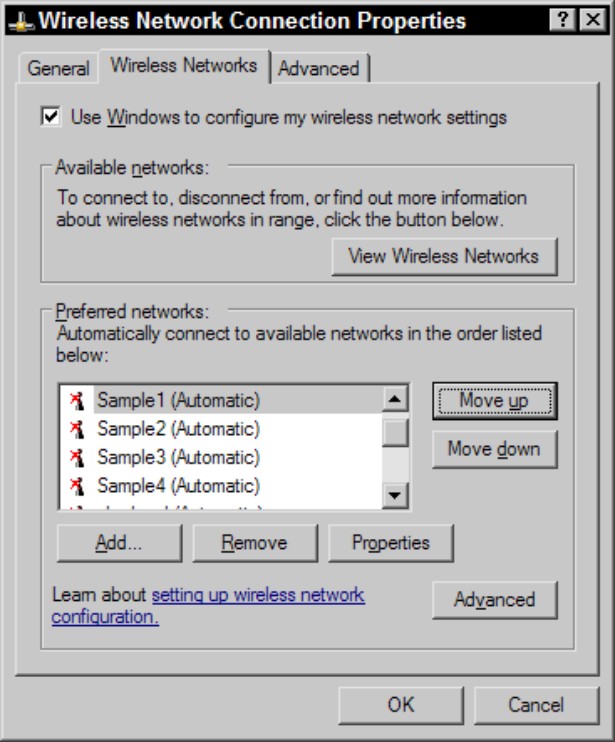
5. Click the Wireless Networks tab in the Wireless Network Connection Properties dialog box (shown in Figure 2-3) and click the Add button.
The Wireless Network Properties dialog box opens.
Figure 2-3: Wireless settings for each network connection are found in the network connection’s Properties dialog box.
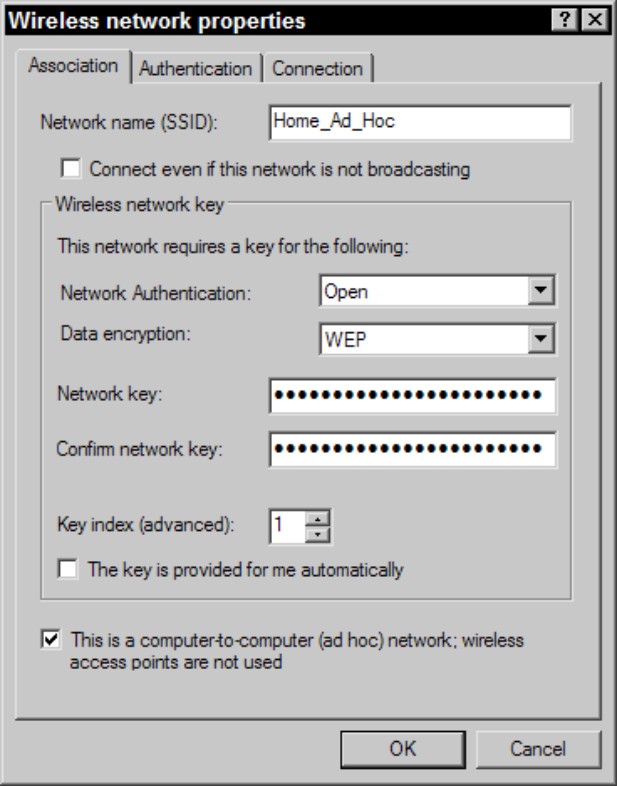
6. Type a name for your new ad hoc network into the Network Name (SSID) text box or type the name of an existing network.
7. Select the This Is a Computer-to-Computer (Ad Hoc) Network check box at the bottom of the dialog box.
8. Use the Network Authentication and Data Encryption drop-down lists to select the settings that you would like to use.
9. If the WEP key is not provided for you automatically, deselect the The Key Is Provided for Me Automatically check box and type the WEP key into the Network Key and Confirm Network Key text boxes.
A completed dialog box with these settings is shown in Figure 2-4.
Figure 2-4: Only a few pieces of information are required to set up an ad hoc network.
10. Click the OK button to save your changes and close the Wireless Network Properties dialog box.
11. Click the OK button to close the Wireless Network Connection Properties dialog box.
12. If this is the first device that you have set up for this network, repeat the steps for your second device.
The second computer sees the network show up in its list of available wireless networks.
By default, the TCP/IP settings for each network card will be set to use Automatic Private IP Addressing (APIPA), so because you will not have a DHCP server on your ad hoc network, both of your devices will choose a random address in the 169.254.0.0/16 network. This situation should be fine because you can then connect to the devices by either their computer name or IP address.
Activating your ad hoc network in Windows XP
If you have successfully created your ad hoc wireless network connection, then you are halfway on your journey to using the connection. The next step is to tell your computer that you want to use that new ad hoc wireless LAN. You tell your computer that you want to use the ad hoc network by following the appropriate steps for your operating system.
![]() This process is only documented for Windows XP because Windows Vista and Windows 7 do not save these ad hoc connections. To activate a connection, you need to perform the setup again because when the connection becomes inactive, Windows 7 deletes the connection.
This process is only documented for Windows XP because Windows Vista and Windows 7 do not save these ad hoc connections. To activate a connection, you need to perform the setup again because when the connection becomes inactive, Windows 7 deletes the connection.
To active your new ad hoc network, you need to let Windows XP know that you want to use it. It is set up as an on-demand wireless connection. To do this, follow these steps:
1. Click Start and choose Control Panel from the Start menu.
The Control Panel window opens on the screen.
2. From the Control Panel window, choose Network and Internet Connections.
The Network and Internet Connections settings are displayed.
3. From the Network and Internet Connections window, choose Network Connections.
The Network Connection window appears.
4. Locate your wireless network card in the dialog box’s list, right-click on it, and then click the Properties.
The Properties dialog box for that network card appears.
5. Select the Wireless Networks tab.
6. Click the View Wireless Networks button.
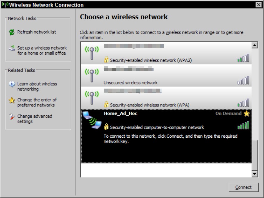
The Choose a Wireless Network dialog box appears, as shown in Figure 2-5.
7. Select your new ad hoc network connection and click the Connect button.
The connection changes to Automatic so that it can then automatically connect when within range.
This network now shows up in the list of available networks for the nearby users, who will see the network when examining the setting for infrastructure networks. (See the later section, “Connecting to a wireless network.”)
Figure 2-5: Connecting to an on-demand wireless connection.
Taking your ad hoc configuration with you
You can make setting up your ad hoc networking easier for use by you and others by copying the configuration to a USB flash drive using the following process:
1. Click Start and choose Control Panel.
The Control Panel window appears.
2. From the Control Panel window, select View Network Status and Tasks.
This opens the Network and Sharing Center.
3. Choose Manage Wireless Networks from the left menu.
The Manage Wireless Networks dialog box appears.
4. Right-click your ad hoc network connection and choose Properties.
The wireless connections’ Properties dialog box opens.
5. Click the Copy This Network Profile to a USB Flash Drive link.
The Copy Network Settings dialog box appears, as shown in Figure 2-6.
6. Insert a flash drive and click Next.
The configuration files for that wireless connection are copied to the USB flash drive, and the completion page is displayed, letting you know what to do next, as shown in Figure 2-7.
7. Click Close.
Figure 2-6: Copying your settings to a USB drive.
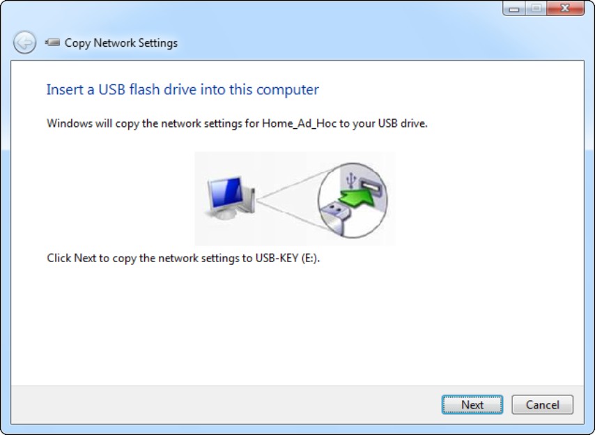
Figure 2-7: Using your settings drive to set up other computers.
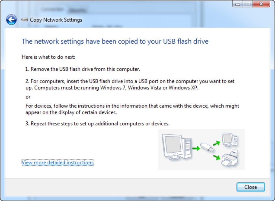
To make use of this USB drive, simply take to any computer running Windows XP, Windows Vista, or Windows 7, and plug the USB drive into any available USB connection. Autorun on the USB drive will take care of the rest and set up your ad hoc network connection. You can repeat this process on as many computers as you like.
You may be curious as to what is on this drive that allows for this magical setup. The drive now contains these files (in addition to whatever you had on the drive before):
• Autorun.inf
• SetupSNK.exe
• Smrtntky folder containing supporting files
The Wsettings.txt file in the Smrtntky folder contains your wireless settings in an encrypted format. Here are the settings for my Home_Ad_Hoc network:
Wireless Network Settings
Print this document and store it in a safe place for future reference. You may need these settings to add additional computers and devices to your network.
Wireless Settings
Network Name (SSID): Home_Ad_Hoc
Network Key (WEP/WPA Key): 12345678901234567890123456
Key Provided Automatically (802.1x): 0
Network Authentication Type: open
Data Encryption Type: WEP
Connection Type: IBSS
Key Index:
To enable File and Printer Sharing on this computer, run the Network Setup Wizard.
To set up your Internet connection, follow the instructions from your Internet Service Provider (ISP).
These ad hoc networks are good to use when you are in a location where you have no infrastructure to which you can connect. Lack of infrastructure can be a problem in boardrooms or meeting spaces that have not been set up to support computers (either wired or wireless), or any other place where you need to connect a few computers. If someone has a small switch and cables, you can use those to set up a small, temporary network, but lacking a wire ad hoc solution, wireless ad hoc is the next best thing.
![]() If you are using Windows to set up your ad hoc networking and you have a computer with a second network card that has an Internet connection, you can use Internet Connection Sharing to allow all the other computers on the ad hoc network to use your Internet connection.
If you are using Windows to set up your ad hoc networking and you have a computer with a second network card that has an Internet connection, you can use Internet Connection Sharing to allow all the other computers on the ad hoc network to use your Internet connection.
![]() Beware of the ad hoc networks that you do not know the source of. When making connections in public locations with public wireless access, such as airports and coffee houses, you should check these broadcasted networks prior to connecting to them. In Windows XP, any connection that is ad hoc, is shown as two computers rather than the wireless antenna (these two symbols can be seen in Figure 2-5), is likely not legitimate, and a person monitoring that network’s traffic could attempt to gather information from your computer or from sites you are connecting to. In Windows 7, ad hoc networks look like three connected computers rather than a signal strength bar, both of which are shown in the upcoming Figure 2-10.
Beware of the ad hoc networks that you do not know the source of. When making connections in public locations with public wireless access, such as airports and coffee houses, you should check these broadcasted networks prior to connecting to them. In Windows XP, any connection that is ad hoc, is shown as two computers rather than the wireless antenna (these two symbols can be seen in Figure 2-5), is likely not legitimate, and a person monitoring that network’s traffic could attempt to gather information from your computer or from sites you are connecting to. In Windows 7, ad hoc networks look like three connected computers rather than a signal strength bar, both of which are shown in the upcoming Figure 2-10.
![]() If you connect to a wireless network in Ad Hoc mode that also allows you to connect to the Internet, or any unknown network, you could be subject to a man in the middle attack using network-auditing software such as Cain and Able from Oxid.it. All your passwords could be exposed, including those for secured HTTPS Web sites. (The types of attacks your network may susceptible to are covered in Book VI, Chapter 1.)
If you connect to a wireless network in Ad Hoc mode that also allows you to connect to the Internet, or any unknown network, you could be subject to a man in the middle attack using network-auditing software such as Cain and Able from Oxid.it. All your passwords could be exposed, including those for secured HTTPS Web sites. (The types of attacks your network may susceptible to are covered in Book VI, Chapter 1.)
Infrastructure mode
As opposed to Ad Hoc mode networks, which make wireless connections directly between computers, Infrastructure mode wireless networks use networking infrastructure. In this case, infrastructure refers to switches, routers, firewalls, and access points (APs). Infrastructure mode wireless networking is the mode that you most often encounter in your work as a networking professional supporting networks for clients or in a corporate environment.
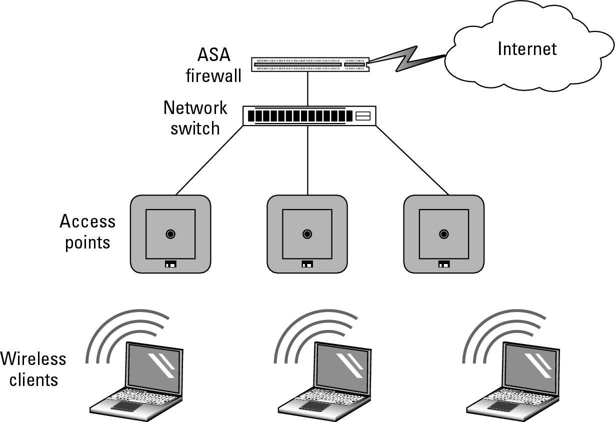
At a minimum, the only network infrastructure component that is required for Infrastructure mode is an access point, but if an AP is all you have, you have no more than you would have had when using Ad Hoc mode. However, most Infrastructure mode implementations include other components from your traditional network infrastructure, as shown in Figure 2-8.
Figure 2-8: A typical Infrastructure mode wireless network.
Connecting to a wireless network in Windows 7
If you are using Windows 7 (or Windows Vista, which is very similar), the process you use to connect to a wireless network is as follows:
1. Click Start and choose Control Panel.
The Control Panel window appears.
2. From the Control Panel window, select View Network Status and Tasks.
This opens the Network and Sharing Center window.
3. From the Network and Sharing Center window, select Set Up a New Connection or Network.
The Set Up a Connection or Network dialog box appears.
4. From the Set Up a New Connection or Network dialog box, select Connect to the Internet.
The Connect to the Internet dialog box appears.
5. From the Connect to the Internet dialog box, select Wireless.
Your available Wireless Networks Connections window appears, as shown in Figure 2-9.
![]() You can also open this by clicking the wireless networks icon in your system tray.
You can also open this by clicking the wireless networks icon in your system tray.
Figure 2-9: Viewing nearby wireless networks with Windows 7.
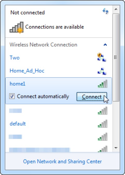
6. Right-click the wireless network to which you want to connect and then choose Connect.
Alternatively, click the wireless network, select the Connect Automatically check box for quick connecting in the future, and then click the Connect button.
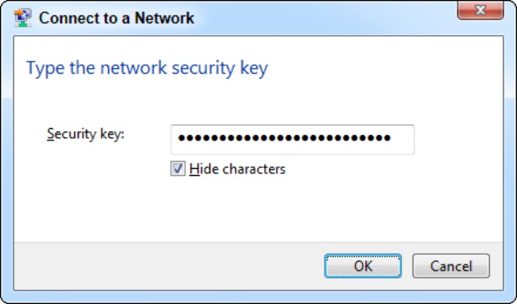
The Connection dialog appears. If the network has no security, you get connected; but if the network is configured for security, then you are asked for credentials based on those security settings. In my case in Figure 2-10, I am asked for the network’s WEP key.
7. Provide the required information and click OK.
When you are connected, you can tell by a lack of other icons associated with the Wireless Networks icon in your system tray.
Figure 2-10: Providing security credentials may be part of making the wireless connection.
After you set up the connection, it will initially become active and will automatically connect to this network whenever it is in range. If you did not choose to save the connection, it will be removed from your wireless configuration when the network is out of range.
Connecting to a wireless network in Windows XP
To connect to a wireless network that is broadcasting its SSID using Windows XP, follow these steps:
1. Click Start and choose Control Panel.
The Control Panel window opens.
2. From the Control Panel window, choose Network and Internet Connections.
The Network and Internet Connections settings appear.
3. From the Network and Internet Connections window, choose Network Connections.
The Network Connection window appears.
4. Locate your wireless network card, right-click it, and choose View Wireless Networks.
The Choose a Wireless Network dialog box appears, as shown in Figure 2-11.
Figure 2-11: This dialog box displays all the networks that are broadcasting their SSIDs.
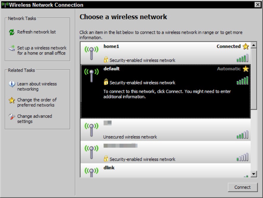
5. Select a wireless network from the list and click the Connect button.
If the network uses WEP or WPA (which are security features you will see in Chapter 3 of this minibook), you are prompted to enter the network key; then click the OK button. Otherwise, your connection is complete and you will be connected to the wireless network.
Enterprise infrastructure access point types
When working with APs in Cisco’s enterprise infrastructure, you will encounter two modes of access points: Autonomous mode and Lightweight mode. If you use hardware from other vendors, their names may be different, but the function and operation will be similar.
Autonomous mode
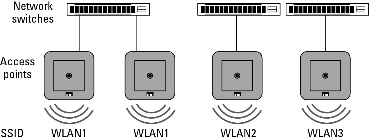
When 802.11 networking began, all APs were Autonomous mode, which means that each AP worked as a standalone unit with no knowledge of or interaction among other APs. Autonomous mode was fine in the beginning when wireless networking was often limited to providing network access in common areas or boardrooms, and continuous roaming was not a requirement. Wireless networks tend to grow, and that means a typical network might deploy from one to ten access points across the network environment, and an environment of that size is still easily managed with Autonomous mode APs. Figure 2-8 shows an example of an Autonomous mode wireless network, where although these APs are connected to the same network, and may use the same SSID, they are all individually configured and separate from one another.
In most small networks, wireless still starts out as an idea to make life a little easier in conference rooms and boardrooms, so these networks tend to start with just one AP in those locations. If you are deploying only one AP on your network, then in all cases you will choose to deploy an Autonomous mode AP.
Unfortunately, after that first AP is deployed and users become used to the flexibility and functionality it offers, you will undoubtedly receive a request for another one.
![]() If you are planning to deploy four or more APs on a new network, you should give thought to Lightweight mode APs because you will be close to the breakeven point in cost between purchasing autonomous APs, and going forward beyond that, you will have an easier infrastructure to manage using Lightweight mode APs.
If you are planning to deploy four or more APs on a new network, you should give thought to Lightweight mode APs because you will be close to the breakeven point in cost between purchasing autonomous APs, and going forward beyond that, you will have an easier infrastructure to manage using Lightweight mode APs.
Lightweight mode
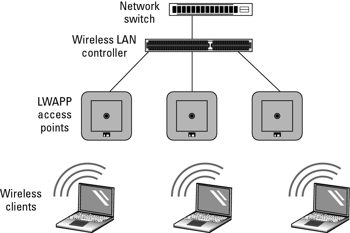
Rather than using Autonomous mode APs, you can use Lightweight mode APs if you have a network component that offers Wireless LAN Controller services. Cisco offers the Lightweight mode option on most of its APs, so you can purchase them with either a controller-based IOS software image (using Lightweight Access Point Protocol, or LWAPP) or a standalone IOS software image (see Book I, Chapter 5 for general information about the IOS). A sample of how the controller and APs fits together in your network is shown in Figure 2-12. Some Wireless LAN Controllers have Power over Ethernet (POE) ports that allow you to connect APs to; you can also connect the AP to any other POE switch on your network. It does not matter where the AP is on your network, it will still get all of its management information from the Wireless LAN Controller.
Figure 2-12: Lightweight APs require a Wireless LAN Controller to be available on the network in order to function.
To have Wireless LAN Controller (WLC) services on your network (which is the management device that manages your LWAPP devices), you can use any of the following:
• Cisco 2100 series controller
• Cisco 4400 series controller
• Catalyst 6500 series Wireless Services Module (WiSM)
• Cisco 7600 series Router Wireless Services Module (WiSM)
• Cisco 28/37/38xx series Integrated Services Router with Controller Network Module
• Catalyst 3750G Integrated Wireless LAN Controller Switch
In this scenario, the access points all have their configuration managed by the WLC. You can set a single policy on that WLC, and that configuration setting can be deployed to all managed access points, reducing the workload of managing hundreds of lightweight access points (when using the Cisco 7600 series Router Wireless Services Module). Also, in this configuration, some of the processing work that would normally be done at the AP can be offloaded to the WLC, leaving more CPU cycles available on the AP.
As mentioned earlier, if you are deploying four or more APs, you should get a quote on a solution that includes lightweight APs and a WLC because the price will likely be similar to the solution with autonomous APs. If you already have Autonomous mode APs, you can convert them to lightweight to blend them into your new managed network, or you can deploy them elsewhere in your organization where lightweight APs will not fit the requirements. Places that cannot use LWAPPs are locations that do not have direct and permanent network connectivity to the WLC, such as isolated segments of your network that have only periodic connections to where the WLC resides. Many of my clients run networks on ships or ocean platforms where there they would require autonomous APs.
Grouping Your Clients with SSID
After you get your hardware identified, mounted, and powered up, how do you get your clients to connect to and manage them? The following sections help you wrap your head around a few more concepts, which deal with grouping your wireless clients into manageable groups.
SSID basics
A service set refers to all the wireless devices that participate in a specific wireless LAN. This wireless LAN may be a local WLAN or an enterprise WLAN, spanning several buildings or areas. Each service set is identified by a service set identifier or SSID. The SSID should directly relate to the network that the WLAN or AP will connect the wireless device to:
• If you have multiple networks within an enterprise environment, multiple SSIDs can exist.
• If you only have one network, you should only have one SSID.
Figure 2-13 shows multiple access points hosting connections to multiple networks. This setup means that in a single area you will likely have multiple APs using the same SSID.
Figure 2-13: Each SSID should identify a different or unique physical network that is allowing connections.
The SSID can be up to 32 characters long. It is usually made up of human-readable ASCII characters, but it could contain any of the possible 256 values in those 32 digits. When users connect to the WLAN identified by the SSID, they can make the connection automatically or manually, depending on how they have configured their network settings on their computers.
Using multiple SSIDs with a single AP
The SSID defines what is thought of as the wireless network, so my SSID is Eds and my neighbor is Bobs, so people can connect to my wireless network or Bobs wireless network. You would expect that my wireless network is not connected to the same wired network as Bobs wireless network is. So you think of those two SSIDs being associated with different physical networks.
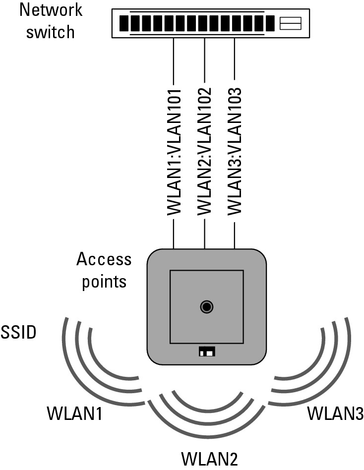
In addition to multiple access points broadcasting or using the same SSID, a single access point can also use multiple SSIDs. Granted, using multiple SSIDs makes sense only if the AP allows you to map each one to a different network connection. This mapping would typically be accomplished through the use of VLAN tagging, as shown in Figure 2-14. If the user’s device associates with a particular SSID, this traffic is then passed to the network switch destined for a specific VLAN. This switch allows each network to have a different set of security standards surrounding it. For example, you may have a wireless network, CorpSSID, which uses certificate-based authentication via WPA2 and AES encryption while using the same APs to provide a second wireless network, GuestSSID, which uses only WEP. Even though you are providing two wireless networks, you can isolate guest traffic from the rest of the corporate network and allow the guest devices to use only some services, such as allowing them through the firewall to get out to the Internet on ports 80 and 443.
Figure 2-14: A single AP can supply access for multiple SSIDs.
Basic service set (BSS)
In simple terms, the BSS is one AP and its collection of clients. The AP is identified by a basic service set identifier (BSSID), which is a unique identifier for an AP and is usually a 48-bit MAC address of the AP. The MAC address allows each AP to be uniquely identified, even though they all may be providing service for the same SSID. The BSSID is used on beacon frame (a periodic broadcast on the wireless network announcing services and the SSID) as a means of identifying each AP.
Extended service set (ESS)
Extended service set (ESS) extends the BSS to more than one AP that shares the same logical link control layer. Effectively, if these APs share the same physical connection to the network or exist on the same physical segment, they can act as one unit with multiple radios, thereby increasing the possible throughput available on that AP. All the BSS units that make up the ESS would share the same SSID and would work on the same or different channels.
The benefit of the ESS is that it allows client roaming without interruption to network traffic or reconfiguration of the client.
Planning Around Interference
You have many factors to consider when planning a wireless network, from external sources of broad-spectrum interference to the characteristics of building materials to channel selection and range. Proper placement of your APs can make your network the talk of the company. Improper placement can make you the talk of the company in not-such-a-great way, with a lot of grumbling, cursing, gnashing of teeth, and with people calling you constantly to ask why they spent so much money on a product that does not seem to be working. (I try to avoid making people unhappy with IT purchasing decisions, preferring to have successful rollouts of new technologies with my users being happy.)
RF signal factors
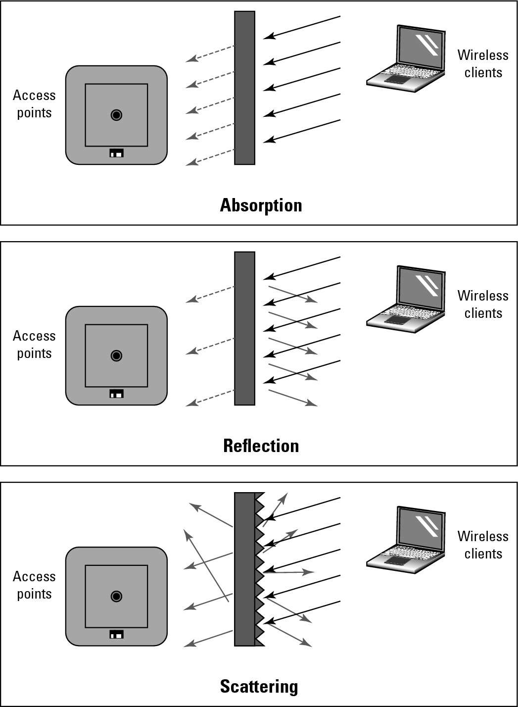
Many factors influence radio frequency (RF) signals. You may get signal loss from building materials that usually comes from three main sources, which are based on the types of materials used. These three sources are as follows and are illustrated in Figure 2-15:
• Absorption occurs when RF waves are absorbed by the materials that they are attempting to pass through. Absorption typically occurs when the waves pass through walls or dense materials. Water and concrete have high RF absorption properties. If you need coverage in stairwells, remember that they are mostly concrete tubes with a bunch of diagonal concrete dividers.
• Reflection occurs when RF waves cannot penetrate a surface and are returned or bounced off the surface. Reflection is common with metal and glass surfaces. Reflection is the principle behind a Faraday cage, where the holes on the cage surface are smaller than the wavelength of the radiation or signal that they are attempting to block, thereby blocking the signal that is striking its surface. So even a thin layer of metal containing no holes can effectively block wireless signals from passing through it.
• Scattering occurs when the reflective surface is uneven, which causes many random bounces. A reflective signal may still have enough of its original properties to be used, but a scattered signal does not. In some cases where you cannot get a direct signal through to your location, you may be able to get a strong enough signal from a bounced RF wave, but only if that wave gets bounced off of a smooth surface; if the surface is uneven then the bounced signal will be useless.
The more issues you have with your signal between the client and the AP, the higher the noise level of the signal. Other sources of noise include other devices that operate in the same wireless band as your AP and devices that might cause broad-spectrum interference. Some level of noise always exists, but if the level is too high, the signal-to-noise ratio will be too low to sustain a proper connection.
Conducting a site survey
Just as a highway engineer will conduct a geographical survey of a location before planning and building a road, an IT professional should conduct a wireless survey before installing a wireless network. Factors such as absorptions, reflection, and scattering can cause degradation in the quality of a wireless signal. When conducting a site survey, you goal is to measure the quality of the signal as well as identify potential sources of interference. A site survey allows you to do the following:
• Identify other wireless networks in the area that might conflict with your network as well as other sources of interference.
• Place a temporary AP and measure the signal strength from different areas.
Figure 2-15: Signal interference.
When planning your AP locations, remember to
• Plan deployments in multiple floor buildings because signals will span floors. Remember that you are working in three dimensions.
• Ensure that all areas where roaming is expected will be connected to a common Layer 2 data link.
Many methods of conducting a site survey and many tools are available for you to use. In most cases, people use 802.11 network devices and measure signal strength with some piece of software; but more expensive tools are available to measure signals across the RF spectrum, thereby showing you interference that may exist which is outside the 802.11 wireless network ranges. Because these tools are more expensive, most people who offer to do a site survey do not use this technology.
Because a site survey requires some networking hardware and software, I have several tools in my arsenal. Some of the software does a nice job of collecting data into a report, or I may have to take the collected data and make my own report.
![]() You can use tools such as Network Stumbler (
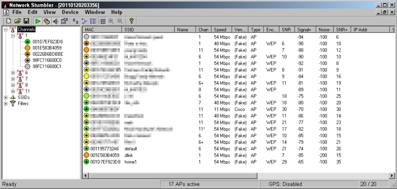
You can use tools such as Network Stumbler (www.netstumbler.com) or MetaGeek’s inSSIDer (www.metageek.net) for free to collect statistics or pay for a tool from a company such as AirMagnet (www.airmagnet.com). Figure 2-16 shows the interfaces for Network Stumbler. The AirMagnet toolsets are very nice and will make creating a polished report very easy.
Figure 2-16: Network Stumbler has both text based and graphical interfaces.
Cisco recommends that, even after I conduct a site survey with these tools, I should then follow up with some pure performance testing using different devices, because I can get a wide range of performance differences based on the antenna gain and application limitations when switching between devices.
You can conduct the site survey using two methods:
• Survey surround signals: This method includes temporary APs that have been set up for your testing purpose. You place these test APs (often when testing you will have just one AP that you move around) close to your expected production locations. Then you test that signal from different locations to get a real-world rating for signal strength from various locations and to identify construction in areas that unexpectedly impact performance.
• Performance testing: This method is similar to the first method, but in addition to checking signal strength and sources of interference, you also do some performance testing. The closer to real world this test can be, the better. To perform this testing, you require another device connected to the AP, such as a laptop, running software. At a minimum, the device will be a Windows computer with a shared folder, with which you will copy files to and from (while documenting the transfer times). These times will be compared with results from other locations, providing you with not only signal strength, but also real-world performance.
![]() I once deployed a wireless network for a hotel that was going to be using the wireless network for its 802.11 wireless phones, as well as its corporate and guest network access. These phones needed to work over the entire property, so I had to test signal strength in locations all sorts of areas, including walk-in freezers, stairwells, clock towers, and the parking garage. In many of these areas, I had no previous experience to draw on and had to perform a full suite of testing. Also, the situations for some of the areas were variable (for instance, the garage could be empty or full of reflective metal and glass cars and SUVs), complicating matters further. If you have done your homework, you should be able to get your initial placement of APs mostly correct, but you can expect to have to make some tweaks or moves based on unexpected situations that will arise.
I once deployed a wireless network for a hotel that was going to be using the wireless network for its 802.11 wireless phones, as well as its corporate and guest network access. These phones needed to work over the entire property, so I had to test signal strength in locations all sorts of areas, including walk-in freezers, stairwells, clock towers, and the parking garage. In many of these areas, I had no previous experience to draw on and had to perform a full suite of testing. Also, the situations for some of the areas were variable (for instance, the garage could be empty or full of reflective metal and glass cars and SUVs), complicating matters further. If you have done your homework, you should be able to get your initial placement of APs mostly correct, but you can expect to have to make some tweaks or moves based on unexpected situations that will arise.
Working with Multiple APs
A small wireless network composed of one AP connected to wired infrastructure makes it fairly easy to manage your wireless RF spectrum — you need to worry only about placement, channel selection, and the location of surrounding APs from your neighbors. This process gets somewhat more complicated when you are deploying multiple APs throughout a multi-story building, because in addition to your neighbors APs you need to worry about location, channel selection, and interference from your old APs with each other.
Selecting channels
I said in Chapter 1 of this minibook that you have only three channels to work with in North America when dealing with 2.4 GHz networking. Some people have suggested that you can get away setting up your channels in a four-channel manner by using channels 1, 4, 8, and 11. This setup would give you overlap in the shoulder area of the bands, but the overlap would be fairly small.
Cisco has done lab testing of the concept using four APs and four clients all transferring 50MB files to and from a server. Even with this limited overlap, data ends up being lost, and stations or computers wait their mandatory wait periods and retransmit data. These problems slow down the overall throughput. Table 2-1 shows the final results. So if you are told that you can use four channels when making your channel selections, this is not advisable and you should stick to the reliable and time tested three channel configuration.
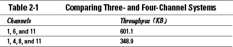
AP layout
I have already said that the simplest wireless network contains only one AP and that the issues that you need to deal with for one AP are generally placement and signal loss. Figure 2-17 shows a centrally located AP in an office with a few obstructions that may cause signal loss in the unshaded areas. In addition to the obstructions and construction material, there may be various sources of external interference that can reduce the size of the coverage area.
Figure 2-17: Signal loss in a single AP WLAN deployment.
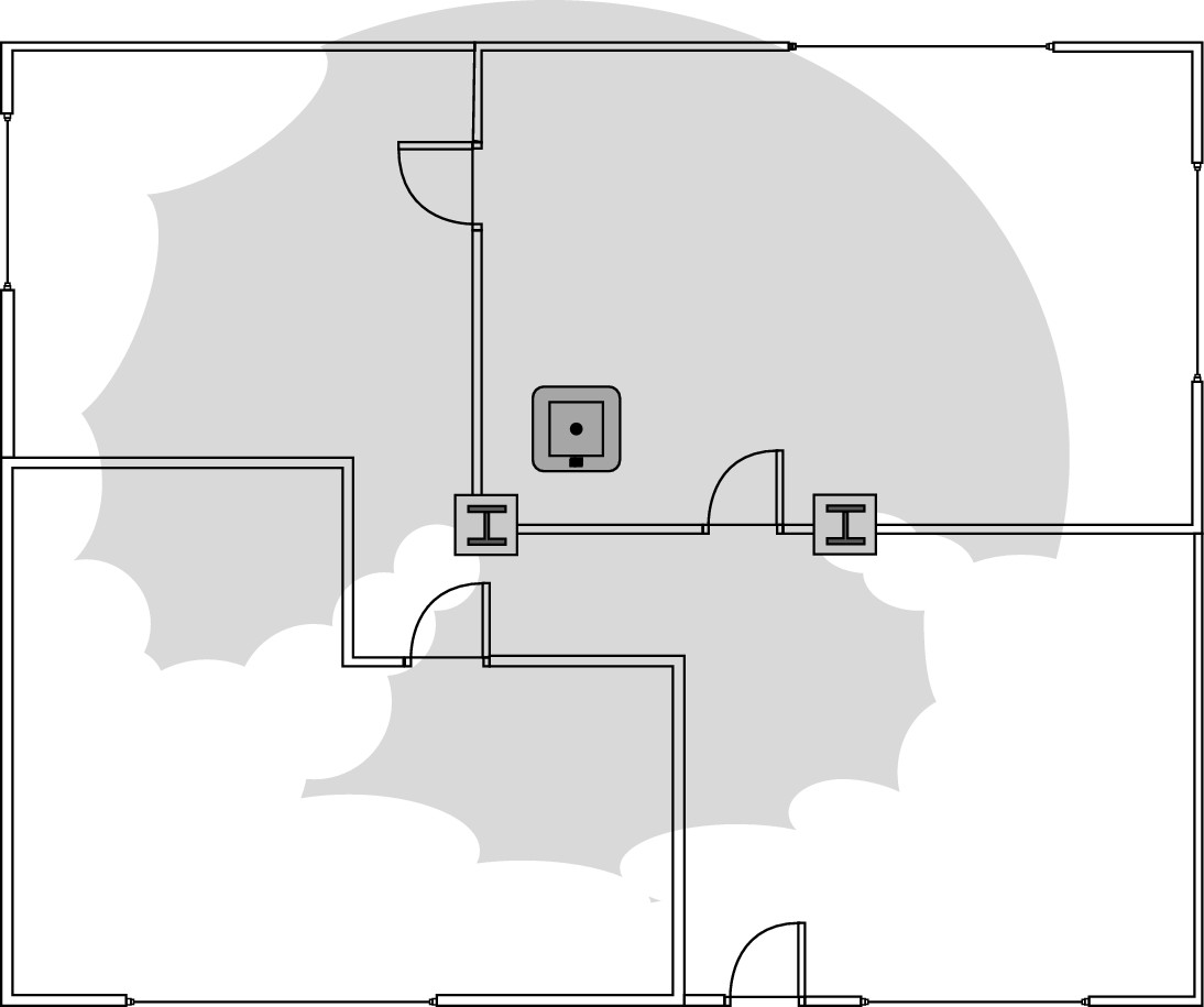
Ignoring signal loss from building materials, if you have three APs in your layout and no outside interference, you should use all three of the non-overlapping channels (1, 6, and 11). The only exception to this would be if you had a more linear layout, where the APs at either end of the line were isolated by the middle AP. A typical pattern may give you a layout that resembles what is shown in Figure 2-18. Cisco recommends a 10–15 percent overlap between APs to allow complete coverage in the interim area, 15–20 percent for VOIP solutions.
This deployment would be more complex if you had to provide coverage using four APs. In that case, you would have to reuse at least one of the non-overlapping channels to complete the deployment. You can do that by isolating the AP with the reused channel from the other AP (which is using the same channel) by having stronger signals from the intermediary APs separate them. Staggering these AP channels allows you to provide coverage on all your network APs. An example of this is shown in Figure 2-19, where the two APs on channel 6 are separated by the combined signals from the APs on channels 1 and 11.
Figure 2-18: Three APs on your wireless network usually require that all three non-overlapping channels be used.
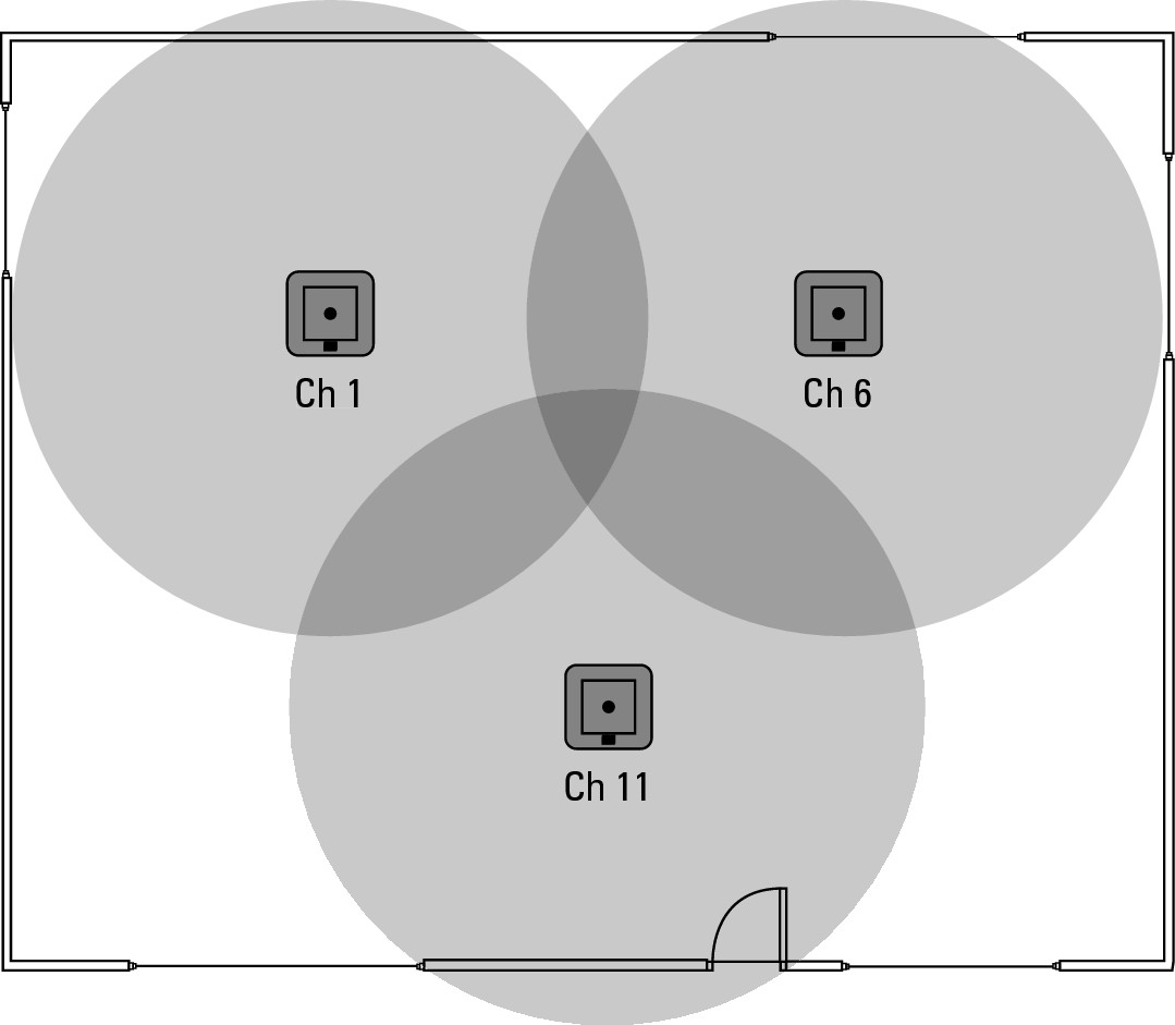
Figure 2-19: Isolating reused channels placing other AP signals in between.
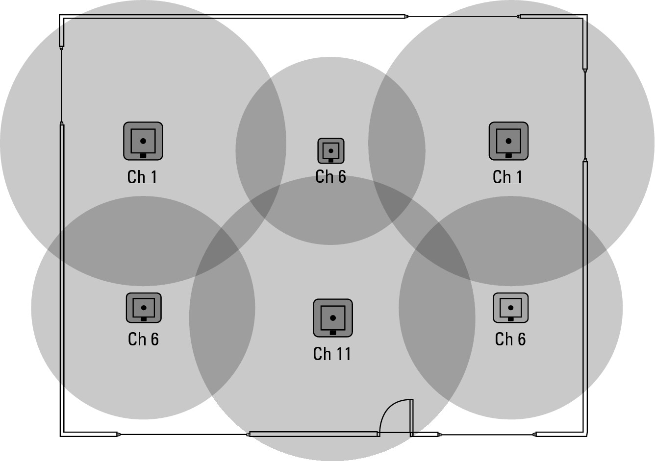
If the area gets even more crowded, in an attempt to provide better coverage or to support higher client density, you may need to take additional steps. In Figure 2-20, notice that
• An AP on channel 6 separates the two channel 1 APs, allowing that channel to be reused.
• All three channel 6 APs are primarily separated by the channel 11 AP.
• In addition to the physical placement, the power levels on the channel 6 APs have been reduced to provide a lower radius of coverage, thus preventing these APs from touching each other.
![]() Having been involved in some large wireless rollouts, I can tell you that channel selection gets even more complicated when you have to do this type of RF management across a three-story building. In that case, you have to keep your channels separated not only per floor but also between floors.
Having been involved in some large wireless rollouts, I can tell you that channel selection gets even more complicated when you have to do this type of RF management across a three-story building. In that case, you have to keep your channels separated not only per floor but also between floors.
Figure 2-20: Tuning radio strength or power can also isolate duplicate channels.
Automatic tuning
Some APs on the market support automatic tuning of channel numbers and signal strength, where the APs on the network identify each other and adjust their radio channels and signal strength to provide optimal coverage, even with APs from other organizations in close proximity. In challenging environments, you may need to actively manage your APs radio settings. Systems such as Cisco’s Wireless LAN Controller, which knows about all internal network APs and can detect external APs, give you a good option for automatic tuning of channels and signal strength.
In automatic tuning, each AP goes off-channel for a short period of time to allow the AP to scan all channels to look for interference. Going off-channel means that there is a brief period when it ignores the wireless client devices that are connected to it, and does its scan of the other channels. This interruption is very brief, so the wireless clients will not be affected, other than a slight decrease in overall throughput. Because the Wireless LAN Controller also knows about all other APs that exist on the network, it can determine the strength and visibility of the surrounding APs. Knowing the strength and visibility of both its own APs and surrounding APs allows the WLC to recalculate the channel selection and radio strength of all APs on the network, thereby optimizing coverage over the whole network.