Chapter 4: Building a Cisco Wireless Network
In This Chapter
![]() Introducing a wireless local area network
Introducing a wireless local area network
![]() Simplifying with Wireless LAN Controllers
Simplifying with Wireless LAN Controllers
![]() Getting the lowdown on Lightweight Access Point Protocol
Getting the lowdown on Lightweight Access Point Protocol
![]() Setting up a wireless LAN
Setting up a wireless LAN
As a network support professional, you need to understand which components make up a standard Cisco wireless network. Earlier chapters in this book show how to do some of the basic configurations for a wireless network. This chapter focuses on the management and configuration of a wireless network based on the Cisco Wireless LAN Controller. I show you how to deploy standalone or controller-based access points and what you need to do to deploy either wireless infrastructure. Along the way, I prepare you to make your deployment decisions by providing you with an overview of the components and letting you know how they work together. With this information, you can make informed choices for your network.
![]() Although this chapter just touches on the configuration for any of these solutions, you can go to Cisco’s website and download the current Cisco xx00 Series Wireless Controller Installation Guide as well as the Cisco Wireless LAN Controller Configuration Guide. The installation guide walks you through the physical setup of the device, and the configuration guide primarily walks you through the software configuration of the device.
Although this chapter just touches on the configuration for any of these solutions, you can go to Cisco’s website and download the current Cisco xx00 Series Wireless Controller Installation Guide as well as the Cisco Wireless LAN Controller Configuration Guide. The installation guide walks you through the physical setup of the device, and the configuration guide primarily walks you through the software configuration of the device.
Introducing the Cisco Unified Wireless Networks Architecture (CUWN)
In today’s technology market, the driving force behind mobile computing is actually mobile computer users. These users find it more and more convenient to be able to use their computing devices wherever they need to do a task. The more places that they can use their devices, the more places they want to be able to use them. The more they talk to other mobile users in their travels, the more ways they find out they can use their devices — as well as how they cannot use them. This push for more mobility while maintaining corporate accessibility gives corporate IT staff members a challenge in that they are typically concerned with the integrity, safety, and security of corporate data; allowing users in an ever-widening geographical area to have access to this data in ever-increasing new ways goes against the typical goals of corporate IT staff, which is to keep data as private as possible. To alleviate some of this concern, Cisco released information on the Cisco Unified Wireless Network (CUWN), which is less a product than it is a methodology and an integrated use of existing products. The unified part of this solution is that it incorporates a standard management methodology and goal across all the products that Cisco provides for both wired and wireless data communication, with data security in the front of all development thoughts.
So the CUWN takes data from a client through wireless access points and wired infrastructure to the servers or devices that will ultimately hold the data. As such, CUWN makes use of networking devices at all levels of the process, and Cisco offers tools to allow central management of all these devices through a series of management tools.
The Cisco Unified Wireless Network uses some or all the following components:
• Cisco Wireless Control System (WCS)
• Cisco WCS Navigator
• Cisco Wireless LAN Controller (WLC)
• Cisco Wireless LAN Controller Module (WLCM)
• Cisco Wireless Services Module (WiSM)
• Cisco Catalyst 3750G Integrated Wireless LAN Controller
• Cisco Controller-Based or Lightweight Access Point (LWAP)
• Cisco Aironet Wireless Bridge
• Cisco Aironet 1500 Series Controller-Based or Lightweight Outdoor Mesh Access Points
• Cisco Client Devices
The following sections look at some of these components in more detail.
Keeping it simple with Wireless LAN Controllers
Management of wireless local area networks (WLANs) can be challenging today with the widespread deployment of access points (APs). In networks where there is currently no wireless access, IT staff experience pressure to deploy a wireless solution; in established networks, the pressure is usually to increase coverage in the current solution. Cisco makes this easier for IT staff through the Cisco Unified Wireless Network, in which a wireless control module of some type is the central or key component. This control module can be a standalone component like the Cisco 2100 Series Wireless LAN Controller or could be integrated into another device like the Cisco Catalyst 3750G Integrated Wireless LAN Controller; in either case, the WLC components allow you to centrally manage and configure a number of access points (APs) in a simplified manner.
![]() If you are going to deploy more than three APs on your network, either to start with or later on, seriously consider deploying a WLC-based solution.
If you are going to deploy more than three APs on your network, either to start with or later on, seriously consider deploying a WLC-based solution.
WLC equipment
To have Wireless LAN Controller (WLC) services on your network, you can use any of the following:
• Cisco Small Business Pro Wireless Express 526 Mobility Controller with 521 Wireless Express Access Point (simplified management)
• Cisco 2100 series controller
• Cisco 4400 series controller
• Cisco 5500 series controller
• Catalyst 6500 Series Wireless Services Module (WiSM)
• Cisco 7600 Series Router Wireless Services Module (WiSM)
• Cisco 28/37/38xx Series Integrated Services Router with Controller Network Module
• Catalyst 3750G Integrated Wireless LAN Controller Switch
The Cisco Wireless LAN Controller is used to manage all aspects of multiple APs and can also take care of all your Radio Resource Management (RRM). RRM is the term given to managing your wireless radios, and it includes not only channel selection and signal power, but also deals with managing interference from unknown sources.
The two WLC devices that you will likely encounter most often are the Cisco 2100 series controller or the Cisco 5500 series controller.
• The Cisco 2100 series controller: This controller has eight network ports on it; two ports support POE to power APs, and the other ports can be assigned as management interfaces or assigned to support various VLAN and network connections that you may be using to isolate traffic for your SSIDs. This WLC system can manage up to 24 APs.
• The Cisco 5500 series controller: Depending on the model of the Cisco 5500 series controller you look at, you can manage up to 500 APs through up to eight network ports (transceiver slots), which are used as distribution system ports. This series of controller is typically connected to a network switch, which would provide network services for your APs.
WLC features
Most WLCs support the following features:
• Distribution system ports: These ports are used to connect the WLC to a network switch and act as a path for data.
• Service port: This port is used as a management or console port. This port is active during the boot mode of the WLC.
• Management interface: This interface is used for in-band management and provides connectivity to network devices (such as DHCP servers or Radius servers). If you want to connect to the controller’s web management interface, it would be through this interface. The management interface is assigned an IP address and is the initial point of contact for Lightweight Access Point Protocol (LWAPP) communication and registration. (See the “Lightweight Access Point Protocol (LWAPP)” section a bit later in this chapter.)
• AP-manager interface: This interface is used to control and manage all Layer 3 communications between the WLC and lightweight APs.
![]() For the best AP association results, the AP-manager interface should be assigned to the same IP subnet as the management interface.
For the best AP association results, the AP-manager interface should be assigned to the same IP subnet as the management interface.
• Virtual interface: This interface is used to support mobility management features, such as DHCP relay and Guest Web Authentication.
• Service-port interface: This interface is used to communicate to the service port and must have an IP address that belongs to a different IP subnet than that of the AP-manager interface and any other dynamic interface.
• Dynamic interfaces: These are VLAN interfaces created by you to allow for communication to various VLANs.
WLC features with LWAPP
When working with a WLC, you can manage autonomous-mode access points or lightweight-mode access points (LWAPs), both of which I discuss in Book V, Chapter 2. Supporting autonomous-mode access points allows you to introduce a WLC into an existing Cisco wireless environment, but saves the initial cost of replacing all the existing access points with LWAPs. Although you do not need to convert your existing APs to LWAPs, some features work only when you use Lightweight Access Point Protocol (LWAPP).
Some features that are available to you when working with the WLC and LWAPP include
• Controller port mirroring: Allows you to copy data on one port of your controller to another port for diagnostics.
• Controller link aggregation (LAG): Allows you to bond multiple ports together on your controller to allow multiple physical ports to be treated as a single logical port. With LAG enabled, you can support 100 APs on a single 4404 WLC, which still follows the recommendation of 48 APs per port. The 5508 WLC has no AP limit per port, but it does recommend using more than one gigabit port if supporting greater than 100 APs.
![]() The more ports you load balance your traffic over, the fewer bottlenecks you will encounter from this link.
The more ports you load balance your traffic over, the fewer bottlenecks you will encounter from this link.
• DHCP proxy allows you to forward DHCP requests to the normal DHCP servers existing on your network.
• Aggressive load balancing: Distributes wireless clients between APs rather than waiting for clients to naturally migrate between APs. When a user travels through an office, her wireless signal on her connected AP reduces as she moves away from it. Typically, the wireless client remains associated with its current AP as long as it can, and when the signal is very weak, it re-associates with a closer AP. In an ideal world, the client would always immediately associate with the closest AP. Enabling Aggressive mode on the WLC causes the LWAP to force the client to a closer AP rather than waiting for the client to give up its existing AP, which ensures a stronger signal.
![]() Aggressive load balancing provides better performance on the overall WLAN by ensuring that users are always on the closest AP.
Aggressive load balancing provides better performance on the overall WLAN by ensuring that users are always on the closest AP.
• Roaming support: Client roaming support between AP on the same ESS, and also between controllers and subnets, as well as Voice over IP telephone roaming.
• Integrated security solutions: Security solutions built around 802.1x and AAA or RADIUS servers.
• Cisco IDS and IPS support: Cisco provides a full range of intrusion detection systems (IDSs) and intrusion prevention systems (IPSs). LWAPs can be an integrated component of either system.
• Internal DHCP server support: WLC supports an integrated DHCP server, or you can use the DHCP server on your corporate network. In addition, WLC can ensure that all clients on the network have DHCP-assigned IP addresses for additional security. People with static addresses can attempt to be another computer that has specific access to secured network resources. Forcing DHCP addresses to be used prevents this type of intrusion.
• MAC filtering: In Chapter 3 of this minibook, I discuss the purpose of MAC filtering to restrict WLAN access. Although MAC filtering is not a strong security feature, it does have features that many wireless network administrators demand. With WLC, you can specify that all MAC addresses be verified against registered addresses on AAA servers.
• Dynamic transmit power control: Allows the radio strength to be tuned to allow for maximum coverage with minimal interference between APs.
• Dynamic channel assignment: Allows for regular checks of RF channels in use in the area, and assigning channels that provide the least amount of interference or noise.
• Coverage hole detection and correction: Allows for clients that are detected to be getting weak coverage to trigger a process that will re-evaluate the overall channel and signal strength on the network to correct the holes as part of an effective RRM strategy.
• Rogue AP detection and rogue device management: Allows you to identify unmanaged APs in your area and determine whether they are actually on your local network. If they are on your local network, remedial action may be taken. When using rogue device management, unauthorized APs on your environment can have their wireless services interrupted.
Going mobile with Cisco WLAN access point (AP) devices
Cisco Aironet access points are designed to support a variety of environments from indoor to outdoor. The lightweight access points allow users to make use of all mobility features of Cisco’s Unified Wireless Network and support all the standards of 802.11a/b/g/n. These devices offer reliable and secure communications using either single or double radios. The greatest advantage is with “zero-touch” configuration, which allows you to deploy APs right out of the box with no initial prep work.
Having a choice between two radios in an AP allows you to support twice as many wireless clients on one RF frequency (2.4 or 5 GHz) or to support clients on both frequencies at the same time. When using only one radio, you can support clients only on one of the two frequencies, and if you want to support clients on the other frequency, you must install a second AP. So having two radios in the same AP effectively gives you two APs in a single unit. Do not confuse this support for multiple service set identifiers (SSIDs), which I cover in Chapter 3 of this minibook, as even with a single radio, you can support multiple SSIDs.
Cisco’s product line of APs include the following:
• Cisco Aironet 1040 Series is designed as an entry-level device and includes integrated antennas.
• Cisco Aironet 1140 Series is designed for indoor office environments and includes integrated antennas.
• Cisco Aironet 1260 Series is designed for challenging RF indoor office environments and includes external antennas.
• Cisco Aironet 3500 Series are for high-performance and mission-critical environments. They offer models with either internal or external antennas which would depend on the RF challenges in your environment.
![]() These systems can be retrofit into 1130 and 1240 series mounting brackets for easy deployment.
These systems can be retrofit into 1130 and 1240 series mounting brackets for easy deployment.
• Cisco Aironet 1250 Series APs are based on the IEEE 802.11n specifications and provide reliable coverage for all standards based on 802.11 a/b/g/n. This support allows for the use of high bandwidth applications, such as voice. These APs offer rugged metal cases with external antennas and are designed for factories and warehouses.
• Cisco Aironet 1500 Series lightweight outdoor mesh access points are the ideal solution for outdoor areas.
Cisco Wireless Control System (WCS)
The Cisco Wireless Control System (WCS) is a software control system for a wireless network. This software is available from Cisco to allow you to design, plan, control, and troubleshoot a multi-controller wireless environment. Although you can deploy your controller-based wireless network, WCS provides you benefits when your network is supported by multiple WLC units.
![]() Think of WCS as a controller for the WLC.
Think of WCS as a controller for the WLC.
Unlike the other products listed previously in this chapter, WCS is primarily a software solution that runs on a server.
Lightweight Access Point Protocol (LWAPP)
The LWAPP runs on a WLAN controller and on lightweight access points (LWAPs) to route packets in and out of the WLAN on optimal routes. In other words, the WLAN controller is the gateway of the WLAN to the LAN. The key fact here is that if you do not have a functioning WLC running on your network, none of your lightweight APs will be able to function. So when your wireless network hits a level that is considered to be mission critical, it is imperative that you have more than one WLC to which your APs can connect. When you configure your APs on your network, you can assign primary, secondary, and tertiary controllers for your network. If the primary controller is unavailable, the backup controller will be used until the primary becomes available on the network again. And the tertiary controller allows your network when both the primary and backup controllers are unavailable.
![]() Cisco has changed its terminology recently, and LWAPPs are now referred to as controller-based on Cisco parts lists, whereas non-LWAPP or autonomous APs are called standalone.
Cisco has changed its terminology recently, and LWAPPs are now referred to as controller-based on Cisco parts lists, whereas non-LWAPP or autonomous APs are called standalone.
The controller and APs run protocols that route packets in and out of the WLAN and LAN, using the optimum path through the wireless mesh network and through the wired network linking the WLAN controller to other WLAN controllers. Communication between the LWAP and WLC works equally well at layer 2 with switches or at layer 3 with routers.
When working with the WLC and LWAPs, the LWAPP has a Split MAC function that determines which functions are performed by the LWAP and which functions are performed by the WLC.
The WLC usually performs these functions:
• 802.11 authentication
• 802.11 association
• 802.11 frame translation and bridging
• 802.1x/EAP/RADIUS processing
• Termination of 802.11 traffic on a wired interface
The LWAP usually performs time-sensitive operations, such as the following:
• Frame exchange handshake between a client and AP
• Transmission of beacon frames
• Buffering and transmission of frames for clients in power-save mode
• Response to probe request frames from clients
• Provision of real-time signal quality information to the switch with every received frame
• Monitoring each of the radio channels for noise, interference, and other WLANs
• Monitoring for the presence of other APs
• Encryption and decryption of 802.11 frames
If you have already purchased all your access points and they are autonomous, but you now want to roll out a WLC, then you can convert your APs to Lightweight mode by running a Cisco-supplied upgrade tool on your compatible Cisco AP. If you decide that you need to re-deploy some of these APs to locations where you are not using a WLC, you can reverse this process by reapplying the latest Cisco IOS for that Cisco AP.
Setting Up Your Wireless LAN
The following sections give you an overview of the basic process for setting up your wireless LAN. In this case, I focus on a WLAN that will be functioning with a Cisco Wireless LAN Controller (WLC).
Setting up and verifying the wired LAN to which the WLAN will connect
Although setting up a WLAN in your environment is not a huge undertaking, you need to plan and ensure you know a few things before starting the whole process. Nothing is worse than getting halfway through a deployment, only to find out you have to scrap the whole design and start again because part of the current infrastructure does not support a feature you wanted to use. This process assumes the following:
• You have already planned the number and type of service set identifiers (SSIDs) that you will be supporting. SSIDs are defined in Chapter 1 of this minibook.
• You have the VLANs that are required to support them. You will find out more about VLANs in Book III, Chapter 5.
• You have security parameters around the VLANs.
• You have conducted a site survey so that you know where each AP will be mounted. Your site survey knowledge can be located in Chapter 2 of this minibook.
Knowing all these items ahead of time can ease and speed the deployment of your wireless infrastructure.
Setting up the Cisco Wireless LAN Controller(s)
After unpacking your WLC, connect the console cable to the service port and set your computer’s terminal settings to the following:
• 9600 bps
• 8 data bits
• 1 stop bit
• No parity
• No hardware flow control
Mucking about with the Startup Wizard
When powering up your WLC, you need to perform some configuration. You are presented with the Startup Wizard, which does the following tasks:
• Ensures that the controller has a system name of up to 32 characters.
• Adds an administrative username and password, each up to 24 characters.
• Ensures that the controller can communicate with the GUI, CLI, or Cisco WCS through the service port by accepting a valid Dynamic Host Configuration Protocol (DHCP) configuration or manual IP address and netmask.
![]() Entering 0.0.0.0 for the IP address and netmask disables the service port.
Entering 0.0.0.0 for the IP address and netmask disables the service port.
• Ensures that the controller can communicate with the network (802.11 distribution system) through the management interface, having you assign a static IP address, netmask, default router IP address, VLAN identifier, and physical port assignment.
• Prompts for the IP address of the DHCP server used to supply IP addresses to clients and the controller management interface.
• Asks for the Lightweight Access Point Protocol (LWAPP) Transport mode.
• Collects the virtual gateway IP address — any fictitious, unassigned IP address (such as 1.1.1.1) to be used by Layer 3 security and mobility managers.
• Allows you to enter the mobility group (RF group) name, which is just a descriptive name for a group of APs.
• Collects the wireless LAN 802.11 SSID, or network name.
• Asks you to indicate whether clients can use static IP addresses. Allowing this option is more convenient for some users but offers less security. Disallowing this option requires that all devices get their IP configuration from a DHCP server.
• Asks whether you want to configure a Remote Authentication Dial-In User Service (RADIUS) server from the Startup Wizard. If you do want to use RADIUS, you are prompted for the server IP address, communication port, and shared secret (password).
• Collects the country code to ensure that it configures the radios for the local region.
• Enables or disables the 802.11a/n and 802.11b/g/n lightweight access point networks.
• Enables or disables Radio Resource Management (RRM).
Verifying connectivity to the wired LAN
If you have connected your management cable, proceeded through the Startup Wizard, and provided it all the information it required, you now have a running WLC supporting at least one SSID. If you choose to, you can perform any remaining configuration changes either from a remote terminal or via the web-based GUI. Throughout this chapter, I show you how to do your configuration from the command-line interface (CLI), but at the end of the chapter, I give you a quick tour of the web interface. The following sections allow you to configure additional SSIDs.
Enabling the 802.11 bands
Using the command-line interface (CLI), you can enable or disable the supported radios with the following commands:
config 802.11a disable network
config 802.11b disable network
config 802.11a enable network
config 802.11b enable network
config {802.11a | 802.11b} 11nsupport {enable | disable}
To save and view your configuration changes, use the following commands:
save config
show {802.11a | 802.11b}
You then see output that looks something like this:
802.11a Network............................... Enabled
11nSupport.................................... Enabled
802.11a Low Band........................... Enabled
802.11a Mid Band........................... Enabled
802.11a High Band.......................... Enabled
802.11a Operational Rates
802.11a 6M Rate.............................. Mandatory
802.11a 9M Rate.............................. Supported
802.11a 12M Rate............................. Mandatory
802.11a 18M Rate............................. Supported
802.11a 24M Rate............................. Mandatory
802.11a 36M Rate............................. Supported
802.11a 48M Rate............................. Supported
802.11a 54M Rate............................. Supported
...
Configuring the SSID
In the case of Cisco Wireless LAN Controllers, an SSID is configured as part of a WLAN so that each WLAN maps to an SSID. Within the WLAN settings, you can configure security, quality of service (QoS), radio policies, and other wireless network settings. Each controller supports up to 16 WLANs.
The following commands allow you to configure an additional SSID:
show wlan summary
config wlan create wlan_id profile_name ssid
When the WLAN is created, it is automatically disabled for security. After you have completed all your security settings, you can enable the WLAN with the following commands:
config wlan enable wlan_id
save config
Configuring WLAN security
Configuring security settings on WLAN sets is for all your associated access points. You can configure either static WEP or WPA for wireless security.
Configuring WEP keys
To configure static WEP keys, follow these steps based on a specific WLAN ID:
1. Disable 802.1x encryption:
config wlan security 802.1X disable wlan_id
2. Configure the WEP key as 40/64-, 104/128-, or 128/152-bit:
config wlan security static-wep-key encryption wlan_id {40 | 104 | 128} {hex | ascii} key key_index
The default key level is 104, which requires you to enter 26 hexadecimal or 13 ASCII characters for the key.
3. To configure WPA1 or WPA2, use the following commands:
config wlan disable wlan_id
config wlan security wpa {enable | disable} wlan_id
config wlan security wpa wpa1 {enable | disable} wlan_id
4. To enable WPA2, use the following command:
config wlan security wpa wpa2 {enable | disable} wlan_id
5. Choose Advanced Encryption Standard (AES) or Temporal Key Integrity Protocol (TKIP) for data encryption:
config wlan security wpa wpa1 ciphers {aes | tkip} {enable | disable} wlan_id
config wlan security wpa wpa2 ciphers {aes | tkip} {enable | disable} wlan_id
The default values are TKIP for WPA1 and AES for WPA2.
6. Choose a system for authenticated key management, which would be 802.1X, Pre-Shared Key (PSK), or Cisco Centralized Key Management (CCKM):
config wlan security wpa akm {802.1X | psk | cckm} {enable | disable} wlan_id
The default value is 802.1X.
7. When using PSK, set a preshared key:
config wlan security wpa akm psk set-key {ascii | hex} psk-key wlan_id
WPA preshared keys must be 8 to 63 ASCII text characters or 64 hexadecimal characters long.
8. Enable the WLAN:
config wlan enable wlan_id
9. Save your settings:
save config
Setting up Cisco access points
When using a Cisco lightweight APs, you need to set up the WLC to accept registration of APs. This set up is all part of the controller discovery process.
As previously mentioned, Cisco’s lightweight access points (LWAPs) use the Lightweight Access Point Protocol (LWAPP) to communicate between the components of the wireless network infrastructure. In this environment, your access point needs to be associated or linked with a controller to properly function. The discovery process is the system that allows this association to occur. After an access point is associated with a WLC, its full potential can be reached.
1. The LWAP sends a join request to the controller.
2. The controller acknowledges this request by sending a join response to the lightweight access point.
3. The LWAP has permission to become associated with the controller and stores the controller connection information locally.
After the discovery process is complete, the controller can manage all aspects of the lightweight access point, such as its configuration, firmware, control transactions, and data transactions.
Methods for discovering an AP
A lightweight access point can be discovered in the following ways:
• Layer 3 LWAPP discovery: This discovery occurs when the LWAP is on a different subnet from the WLC and the AP uses the IP address rather than the Layer 2 MAC address.
• Layer 2 LWAPP discovery: This discovery occurs when the LWAP and WLC are on the same subnet and the discovery data is placed in Ethernet frames that contain the MAC addresses of the two devices.
![]() Layer 2 LWAPP discovery cannot be used in Layer 3 environments.
Layer 2 LWAPP discovery cannot be used in Layer 3 environments.
• Over-the-air provisioning (OTAP): This option is supported only by Cisco 5500, Cisco 4400, and Cisco 2100 series WLCs. If the option is enabled, all associated access points send neighbor messages. These neighbor messages allow new LWAP devices to receive the WLC’s IP address, where they can conduct the rest of the discovery process. After this process has been completed, the option on the controller should be disabled.
• Locally stored controller IP address discovery: After a discovery has been completed, the AP stores the addresses for its controllers in nonvolatile memory so that, for later deployment, it has all the necessary controller information. This process is called priming the access point.
• DHCP server discovery: This option allows the DHCP option 43 to provide controller IP addresses to the access points.
• DNS discovery: Domain Name System (DNS) information for the controller can be stored in your DNS zone. The record should be called CISCO-LWAPP-CONTROLLER.localdomain, where localdomain is the access point domain name. After the AP knows the IP address of the controller, it can connect to the controller to complete the registration process.
Locating a specific LWAP
From time to time, you may need to locate a specific lightweight access point on your network. The easiest way to do this is to configure the access point to flash its LEDs. This feature is supported on any controller software release 4.0 or later and all lightweight access points. To flash an access point’s LEDs, issue the following command:
debug ap enable Cisco_AP
To cause a specific access point to flash its LEDs for a specified number of seconds, issue this command:
debug ap command “led flash seconds” Cisco_AP
You can enter a value between 1 and 3600 for the seconds parameter. To disable LED flashing for a specific access point, use the following command:
debug ap command “led flash disable” Cisco_AP
Configuring backup controllers
Due to the importance of having an active controller on your network to support your wireless network, you should not rely on only having a single controller on your network. Controllers may be distributed between a central site and regional sites and still manage all APs anywhere on the network. Controllers at the central site and regional sites do not need to be in the same mobility group, and using the CLI on the controller you can specify a primary, secondary, and tertiary controller for your lightweight access points.
![]() Starting with controller software release 5.0, you can configure timers for the primary and secondary controllers so that the time taken to discover a failed primary controller is reduced. If, during that timed interval, a controller has not received any data packets from the other controller, it then sends an
Starting with controller software release 5.0, you can configure timers for the primary and secondary controllers so that the time taken to discover a failed primary controller is reduced. If, during that timed interval, a controller has not received any data packets from the other controller, it then sends an echo request to the controller. If there are no results from the echo, the controller considers the other controller to be failed. From the lightweight access point’s perspective, if a controller fails two consecutive discovery requests, it is considered to be failed.
In all failure cases, the secondary and then the tertiary controllers are attempted to be contacted. When the primary controller comes back on line, the access points automatically fail back over to the primary controller. To configure backup controllers, follow these steps:
1. Configure a primary controller for a specific access point:
config ap primary-base controller_name Cisco_AP [controller_ip_address]
2. Configure a secondary controller for a specific access point:
config ap secondary-base controller_name Cisco_AP [controller_ip_address]
3. Configure a tertiary controller for a specific access point:
config ap tertiary-base controller_name Cisco_AP [controller_ip_address]
4. Configure a primary backup controller for a specific controller:
config advanced backup-controller primary backup_controller_name backup_controller_ip_address
5. Configure a secondary backup controller for a specific controller:
config advanced backup-controller secondary backup_controller_name
backup_controller_ip_address
6. Configure the fast heartbeat timer for local, hybrid-REAP, or all access points:
config advanced timers ap-fast-heartbeat {local | hreap | all} {enable | disable} interval
7. Configure the access point primary discovery request timer:
config advanced timers ap-primary-discovery-timeout interval
8. Save your changes:
save config
9. Verify the configuration changes that you made by using these commands:
show ap config general Cisco_AP
show advanced backup-controller
show advanced timers
Web authentication process
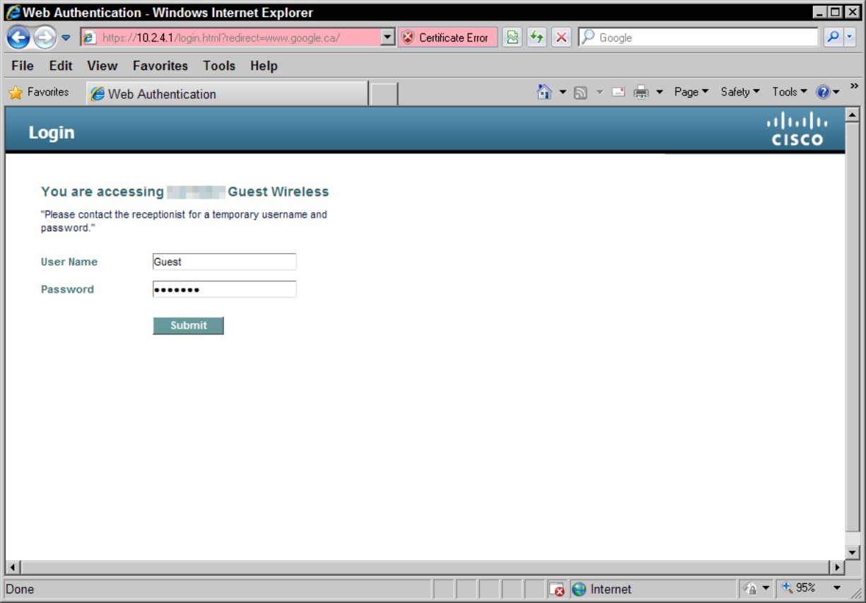
The web authentication process is a Layer 3 security function that allows the controller to block all client IP traffic with the exception of DHCP traffic. After the client has obtained an IP address, the only action that is open to the user is to attempt to connect to a website. Any HTTP-related traffic is then captured. The user’s web browser session is redirected to a default or custom login page, where the user is prompted for authentication information in the form of a username and password.
Because this system includes a self-signed certification, the first time that this process takes place the user is prompted with a security alert that should be accepted.
You have a few options for the login page: The basic controller administration page allows some simple modification of the page text and the presentation of the Cisco logo. The following options are available as login pages:
• The default login page
• A modified version of the default login page (as shown in Figure 4-1), directs users to the receptionist for login credentials. This allows you to provide additional directions for new users, but limits the level of customization.
• A customized login page that you configure on an external web server
• A customized login page that you download to the controller
Figure 4-1: Modified version of default web authentication page.
After the user successfully logs in, he is presented with a successful login page and then automatically redirected to the originally requested URL.
Using the Cisco graphical user interface (GUI)
For both the Wireless LAN Controller and autonomous APs, you also have an option of using the GUI to perform your configuration. This GUI is web-based and can be configured to operate over HTTP or HTTPS. Because the WLC module may be embedded in a switch, firewall, or router, you may find that some WLC management is performed through one of Cisco’s other management interfaces, such as Cisco’s Security Device Manager (SDM) or Adaptive Security Device Manager (ASDM). The SDM can be launched from the web management interface of Cisco’s Integrated Services Router (ISR). The ASDM is the main management interface for Cisco’s Adaptive Security Appliance (ASA) firewalls and is also launched through the web management interface.
Figure 4-2 shows a sample of the web interface used for managing the Cisco 2106 WLC; the interface for the 4400 series WLC and 5500 series WLC is similar.
Figure 4-2: The administration GUI on the Cisco 2106 WLC.
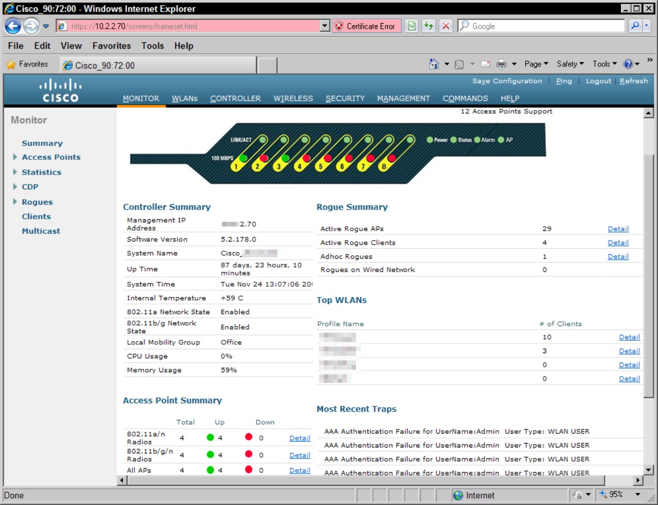
Figure 4-3 shows the management interface for the Autonomous mode Cisco 1250 Series Access Point. Note that its interface appears quite different from that of the WLC you saw in Figure 4-2. In this case, the SSID management is found in the SSID Manager on the Security menu (located in the left menu), whereas the WLC has SSID settings on the WLAN menu.
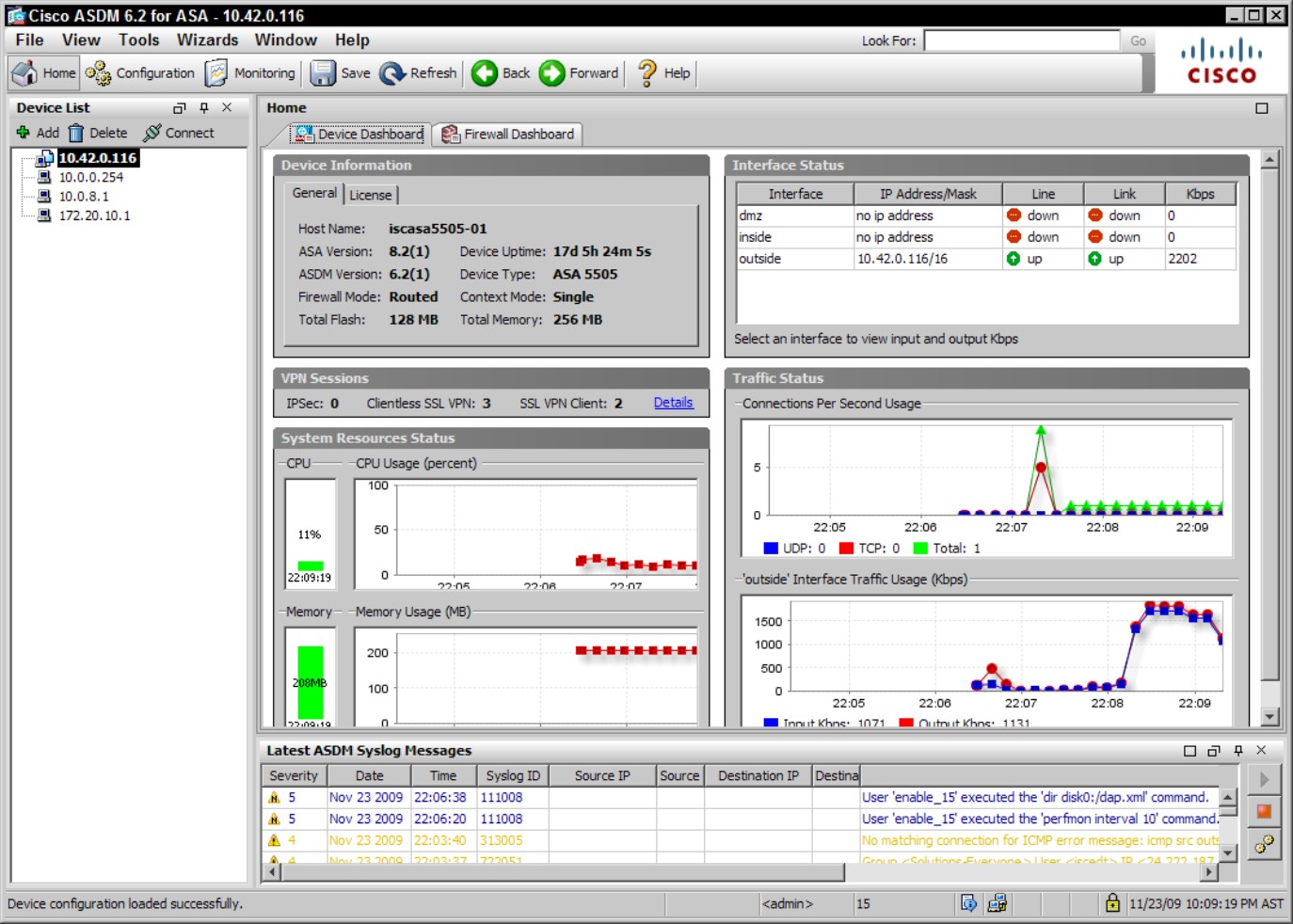
The other interface that is quite different is that of the Cisco ASA firewalls using the ASDM, which is shown in Figure 4-4. This interface is shown only to illustrate the differences in Cisco’s management tools, because the company has a wide set of tools for its appliances. In the case of the ASDM, Cisco uses the web interface on the ASA firewall to launch a Java applet which is the ASDM. By using a Java applet, Cisco has more options available to manage windows and controls (such as radio buttons and check boxes) that can be limiting in a web interface.
Figure 4-3: The administration GUI on the Cisco 1250 Series Access Point.
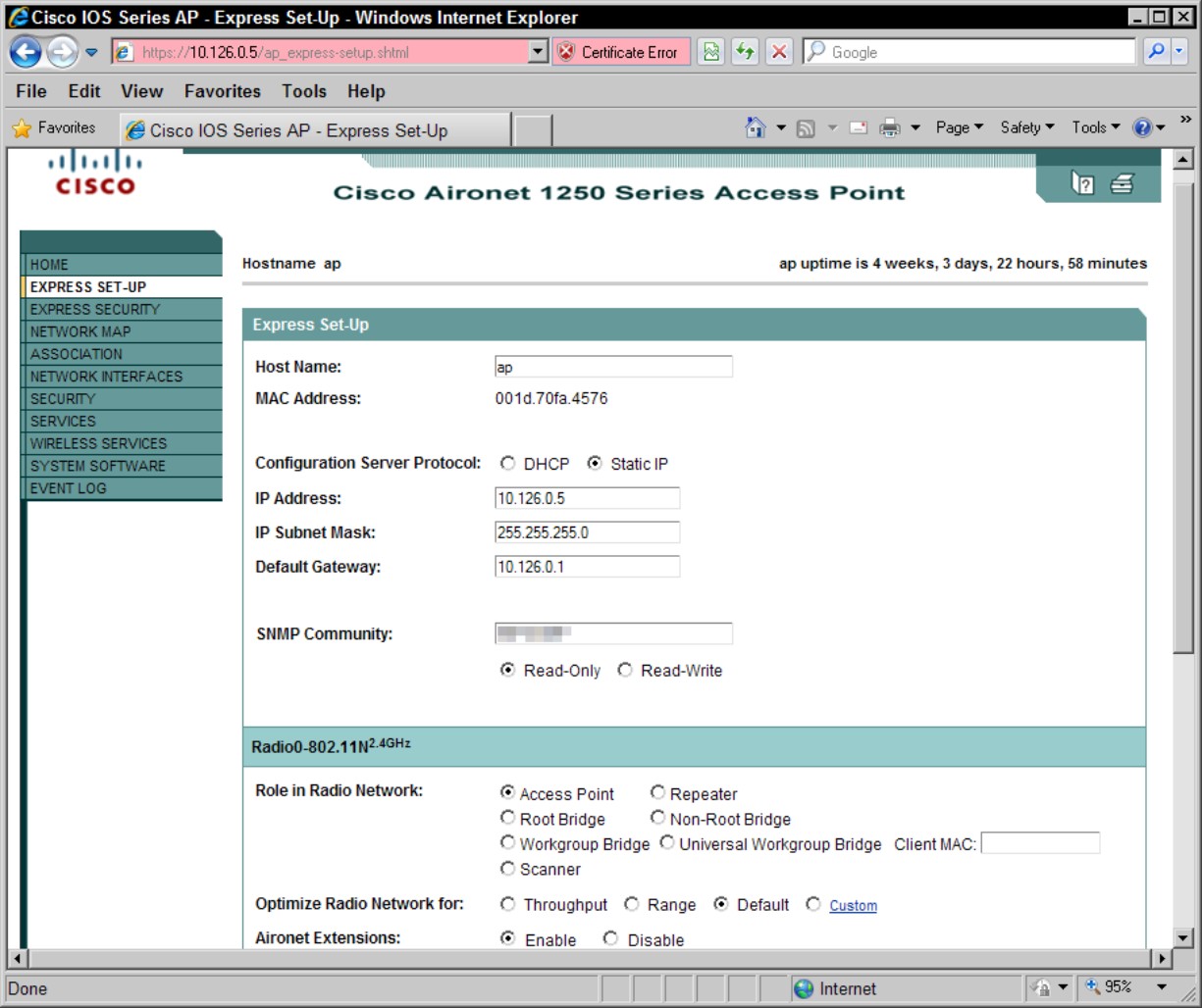
Figure 4-4: The administration GUI on the Cisco ASA 5505 firewall.