
Chapter 1: Looking at the Cisco Network World
In This Chapter
![]() Meeting the OSI model (it does not bite . . . hard)
Meeting the OSI model (it does not bite . . . hard)
![]() Working with switches, routers, and firewalls
Working with switches, routers, and firewalls
![]() Going wireless
Going wireless
![]() Getting your network voice
Getting your network voice
![]() Checking out the Cisco product lines
Checking out the Cisco product lines
If you are reading this book, you likely either have a network that is made up of Cisco networking products or you want to introduce the Cisco network products into your network. Although this book focuses its attention on Cisco products, you do not have to have Cisco network devices on your network to receive a benefit from reading this book. Although you examine many features that are specific to Cisco products, you also gain a wide range of networking knowledge that applies to all networking hardware, regardless of the vendor.
This chapter performs a quick overview of all the devices that exist on your network, allowing your computers, servers, and other user-related network devices to communicate with each other. I start with the network devices that your computer connects to and move further into the depths of the network from there, through routers and firewalls, then through wireless and network-connected phone hardware. After you read about these general hardware devices, you overview the classes of Cisco networking devices, such as enterprise, small business, and home devices.
After you read this chapter, you will have a rough grasp of network devices and how they all fit together on the network and an idea of the type of products that Cisco networking involves.
The rest of this book looks at most of these products and shows you how to configure, manage, and support them. Although some Home products are in this mix, I spend most of the time showing you the products you use on your small or large office network.
Although I do cover the whole network model, I do not go very deep on many of these topics. If you want detailed knowledge of the ins and outs of these devices, you may want to review Book I, Chapter 4.
Glazing Over the OSI Network Layer Model
Well, much as I hate to do this to you so early (mwa ha ha ha), before I discuss the actual devices, you need to understand how the standards-setter in the networking industry, the International Organization for Standardization (ISO), defines how network devices should be designed to communicate with each other. The ISO has proposed a network model that allows for this communication to take place, and although this is good from a theoretical level, it is not always followed, especially since it was published after many networking protocols and methods had been created.
The network model that I describe is the Open System Interconnection (OSI) model, which has seven layers and defines what types of activities should be conducted at each layer. Figure 1-1 shows the seven layers graphically.
Figure 1-1: The OSI network model.
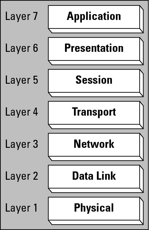
The order of the layers, as they are defined, go from the physical components at the lowest layer (which are used to attach a computer to the network) up to applications at the highest layer that are used on that computer. Some people find that it makes sense to be introduced to the layers in this bottom-up order; while others find the reverse or top-down order is easier to follow. I introduce the layers in the top-down order (highest to lowest as you follow Figure 1-1 from top to bottom), so if you find it confusing, read them from the bottom to the top. The seven layers are
• Layer 7 — Application: The role of the application layer in the OSI model is to interface with you on your computer or data on a server. For example, if you wish to load a page of data from a website, your web browser uses the Hypertext Transport Protocol (HTTP) application layer protocol. To develop a new web browser or web server software, you need only to understand that one application layer protocol. Your HTTP data request travels down through the layers on your computer, over the data network, and up through the network layers on the server, which retrieves the Hypertext Markup Language (HTML) file and returns it in the same manner.
• Layer 6 — Presentation: The presentation layer is responsible for data formatting. This may be character formatting, such as ASCII or Unicode data formats, or compression and data encryption. Think of the presentation layer as the formatting layer in the OSI model. For example, many web servers can compress data that is sent to the web browsers. This compression is the presentation layer component, and it needs to be understood by the presentation layer on the receiving computers.
• Layer 5 — Session: The session layer establishes a communication dialogue between the two participants in the communication process; that is, two computers over a network. After you have a piece of data that is formatted properly, the session layer ensures that it is ready to be sent over the network.
For example, if the OSI model was used by the post office, the application layer identifies the data on a sheet of paper, the presentation layer defines that the paper must be in an envelope, and the session layer defines that the envelope must have a properly formatted address on it — including a name, street number, street name, city, state, and zip code — and preferably, a return address as well.
• Layer 4 — Transport: The transport layer defines what type of checks may be performed to validate the data’s delivery as either reliable or unreliable. Reliable delivery ensures that the data packets get to where they are supposed to go and that they arrive in the same order they were sent. Unreliable delivery does not guarantee that the data packets arrive in any specific order, and in fact, does not even ensure that the data packets arrives where it is supposed to go, at all.
Staying with the post office example, reliable delivery allows you to request a signature of the recipient and get a tracking number, whereas unreliable delivery just gives you a stamp and a post office box. Although most unreliable delivery does arrive where it is supposed to, you are never really sure whether it has, until you somehow confirm with the other party.
On your data network, some data is sent unreliably, such as a request for an Internet Protocol (IP) address from a network server. Other data is sent reliably, such as saving a file to a server.
• Layer 3 — Network: The network layer uses logical address and routing. Logical address applies an address that means something to the communication protocol that you are using, such as an Internet Protocol (IP) address, but may not mean anything to the physical delivery process, which makes use of a Layer 2 address. Routing the data delivers it to the required destination, which may be nearby or very far away. The network layer also splits large pieces of data into smaller pieces for delivery.
To continue the post office example from the Layer 5 discussion, you had to provide a properly formatted address to get your letter to a building or office for delivery by the postal service. Each part of the address has a zone (or place) where it is used, such as the zip code used by the postal sorting and routing department, the street address used by the mail carrier, and the name by people at the destination address. Depending on how mail delivery starts in your organization, some of this required information for the address may have originally been missing from the envelope. The mail delivery process may have started by dropping a letter addressed to John Smith, New York Office in your desk’s outbox. That letter is picked up by your mail clerk who appended John’s office number and the street address of the New York office. He then delivered (or routed) it to the postal service or courier company.
On your data network, this logical address is likely your IP address, which is used as a unique identifier on the Internet to determine the endpoint for communication. IP routing moves the data through a series of interconnected networks until the data arrives at the targeted computer or device.
• Layer 2 — Data Link: The data link layer assigns or makes use of physical addressing as well as controlling access to the physical medium. If you are dealing with standard Ethernet network cards, the manufacturer assigns a globally unique address to each card. This address is the Media Access Control (MAC) address, and it is used at that data link layer to establish communication between two locally attached devices.
The data link layer also controls how the data is interchanged between these two locally attached devices or network cards. Think of this layer as a physical language or a set of communication processes. When dealing with your network, two of the main communication processes would be either Carrier Sense Multiple Access with Collision Detection (CSMA/CD) or carrier Sense Multiple Access with Collision Avoidance (CSMA/CA). In the case of standard Ethernet networks, CSMA/CD is used, while CSMA/CA is used for AppleTalk and some 802.11 wireless networks. With this defined, the data link layer formats a stream of zeros and ones that are converted to electrical or visual signals that are sent over the network.
• Layer 1 — Physical: The physical layer is to perform management and transfer of the actual electrical or visual signals that are placed on to the physical networking media. On your network, this layer consists of the cables and connectors used to send the data signal from point to point.
![]() You can use two mnemonic phases to remember the order of these layers. From Layer 1 up, it would be Please Do Not Throw Sausage Pizza Away; from Layer 7 down, it would be All People Seem To Need Data Processing.
You can use two mnemonic phases to remember the order of these layers. From Layer 1 up, it would be Please Do Not Throw Sausage Pizza Away; from Layer 7 down, it would be All People Seem To Need Data Processing.
When thinking about the OSI model, picture it on both the sending and receiving computers. Imagine that a piece of data moves through the process from one computer to another, and as that data passes each layer, a header, or a modification, is performed on the information at each layer. As the data moves through the system, only the application layer needs to know anything about the data’s actual content, but each layer needs to know how to deal with the layer before and after it (for example, the session layer needs to know how to communicate with the presentation and transport layers). ISO figured that if a group wanted to write a new session interface, they could substitute it at the session layer, without knowing anything about layers any further away than directly before or after it.
Figure 1-2 illustrates the process of data movement by showing the flow of a piece of data — in this case, a get request from a web browser — through the layers and traveling between two computers. The first thing that happens is that the application layer applies a header to the data with relevant information related to the application that is used with this data. This application layer header is used by both the presentation layer to identify where the data came from as well as by the application layer on the receiving computer to send the data to the correct application. The application layer hands off the data — with its application header — to the presentation layer, which considers everything that it has received from the application layer as its data. The presentation layer also applies a header, possibly identifying the character formatting (ASCII or Unicode) and hands off the data — now data and two headers — to the session layer. This process continues with each layer applying a header with relevant information for the receiving computer to use to move the data to the correct application, with layers like the session layer identifying the session as http; the transport layer header identifying reliable transport being required; the network layer identifying the source and destination IP addresses; the datalink layer identifying the local network source and destination MAC addresses; and finally, the physical layer converting this to a sequence of signals to send out across the physical wire or media.
Figure 1-2: Data flows through the OSI model.
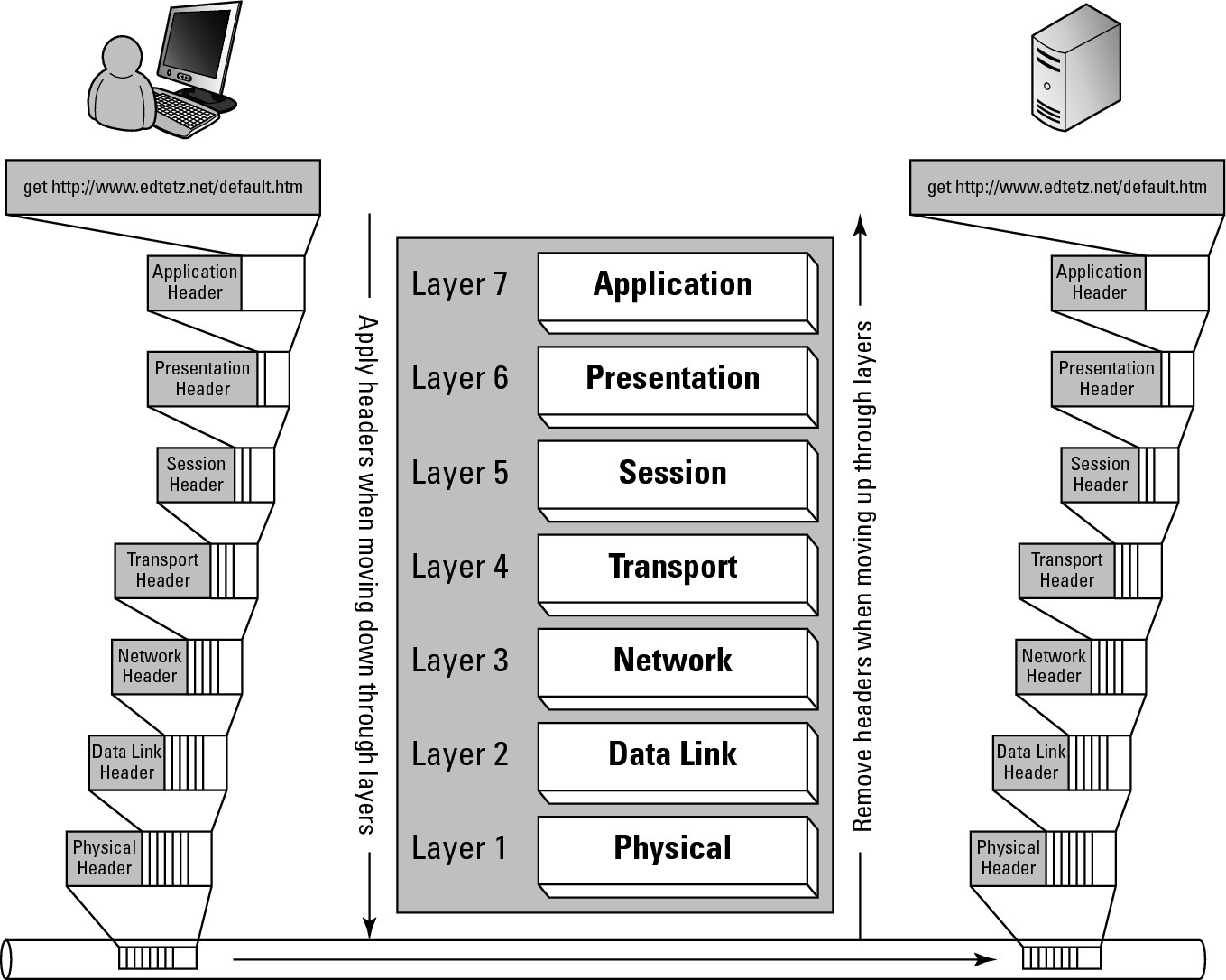
When the data arrives at the destination computer or device, the physical layer receives the series of signals and converts into a format the computer can understand. It then reads the header on that data, which would be the data link header, and passes all of the data it received — minus the physical header — to the data link component identified in the data link header. The data link components would examine the data link header on the data, which identifies any processing that needs to be done at the data link layer, to ensure that they were supposed to receive the data, remove the data link header from the data, process the data, and read the network layer header. The data link layer would use the information in the network header to identify which network layer component was supposed to receive the data and pass it onto those components. In this manner, the data will make its way up through the layers on the receiving computer, with each layer removing its own header, performing any necessary actions on the remaining data, and using the next header to identify where to send the data. As the information makes its way to the application layer, the application layer will read the application layer header, perform any final changes to the data based on instructions in the header, and pass the data to the computers destination application — which, in this case, would be a web server application.
After the web server has retrieved the requested data — the contents of default.htm — the data would have an application header attached to it, and the whole process of sending the information back to the other computer would proceed down through the layers, over the network, and back up through the layers on the receiving computer. The final result would be that the web page, default.htm, would be displayed in the computer’s web browser.
Connecting with Switches
With that introduction to the networking model out of the way, you can deal with the basic classification that the networking community performs with networking devices. This classification is based on the OSI network model layers at which the devices operate, specifically with switches (data link layer or layer 2 devices) and routers (network layer or layer 3 devices). While you could always refer to switches as data link layer device, IT professionals tend to prefer shorter options if available — as noted by the proliferation of acronyms — and will usually refer to them as layer 2 devices. So if you hear people discussing layer 2 and layer 3 devices, think switches and routers. If you are confused by this concept, I clear that up in this section. (Oddly enough, referring to a web server software as a layer 7 device has never really caught on. Thankfully.)
A switch is the main device that connects network devices. Prior to switches being used on data networks, repeaters, hubs, and bridges were used. Repeaters and hubs — also known as multiport repeaters — amplify the physical signal on the network cable, often amplifying noise as well, leading to degenerated data signal in the physical layer or layer 1. Bridges, on the other hand, work at the data link layer or layer 2, where they read the data provided to them from the physical layer, recompose the entire data structure, and send it back to the physical layer to retransmit cleanly over the network media. Switches act as multiport bridges, so they look like hubs with a large number of RJ-45 or other data jacks, but operate on the network in the same way as bridges, at the data link layer.
![]() Hubs simply amplify the physical signals on the wire, whereas bridges and switches operate a layer higher, actually reading the data represented by those physical signals and retransmitting a perfect copy of the original piece of data. Switches work at the data link layer and can read and filter data based on the data link or MAC addresses.
Hubs simply amplify the physical signals on the wire, whereas bridges and switches operate a layer higher, actually reading the data represented by those physical signals and retransmitting a perfect copy of the original piece of data. Switches work at the data link layer and can read and filter data based on the data link or MAC addresses.
Unlike a bridge that separated a larger network into pieces, a switch expects each port to have one computer connected to it, but it can deal with having another switch or hub connected to its ports.
Because a switch makes the connection to a computer, most networks have more switches than any other device. Each switch port typically has a number of lights associated with it to identify that something is connected to that port, as well as activity on that port, link speed, or duplex settings. You can find the core discussion about switches — how they work, how they fit into the overall network, and what duplex means — in Book III, Chapters 1 and 2.
Moving On Up with Routers
Switches connect multiple computers together on a network, and routers connect these networks together. Routers operate at a higher layer in the OSI model than switches do: switches are layer 2 or data link-layer devices that work with data link addresses, whereas routers are layer 3 or network layer devices that work with network protocol addresses. The actual network protocols used depends on the protocols that router is designed to work with.
These days, the network protocols typically work using Transmission Control Protocol/Internet Protocol (TCP/IP); in the past, they may have also worked with Internet Packet Exchange (IPX), AppleTalk, Systems Network Architecture (SNA), Xerox Network Systems (XNS), or Digital Equipment Company Network (DECnet).
Although the definition of network can vary widely from one person to another, for a router, a network is what is connected to each of the router’s ports or interfaces. People often refer to their entire internal network infrastructure as the network, and the pieces that are connected to the router are sub-networks, subnets, segments, or network segments.
![]() Through this book, I usually use the term network to describe an internal corporate network, and use network segments when talking about portions of that network or any network sections separated by a router.
Through this book, I usually use the term network to describe an internal corporate network, and use network segments when talking about portions of that network or any network sections separated by a router.
The main purpose of the router is to pass, or route, data from one network segment to another network segment. Each network segment is identified by a network identifier (ID), and the only decision that a basic router makes is to pass the required data to the appropriate network or network segment. This decision to forward the data is based on known remote network segments in the router’s routing table and directly connected network segments. In addition to forwarding the data, when the destination network segment is not directly attached to the router, the router needs to choose which router it will use to get the data one step closer to the destination network segment. Because routers only need to determine if they know about the destination network segment and what other router will be used to get the data to its destination, they can move data very quickly and efficiently.
Many network devices combine functionality, and one basic mixture is to combine switching and routing into one device. When routing functionality is added to a switch, the switch is referred to as a layer 3 (network layer) switch, differentiating it from a normal switch, which operates at layer 2 (the data link layer).
You can find out a lot more about routers in Book IV.
Taking the Network Wireless
Although networking allows for the transfer of information between devices on a network, wired networking has its limitations — most notably, the length of the wire. For a very long time, people have been working on solutions to break the tether of wires. Over the last decade, wireless technologies have grown in leaps and bounds to the degree that they are commonplace.
Although the world has been going wireless, there have always been people concerned about security, and rightly so. Wireless networks have a security implication, even if it is only not being able to precisely identify where the users of your network physically are. As such, some organizations still isolate some of their key systems to protect them.
When users are not concerned about security, or feel that they have mitigated their security risks, having wireless networking can be a great boon. Wireless networks allow for far greater mobility for the users, can simplify your network administration, and reduce wiring costs when adding, moving, and changing equipment.
When dealing with wireless network, you have likely dealt with residential wireless routers. You may think that a wireless router would be a layer 3 device in the OSI model, but this is not exactly true. Remember that multiple devices can be combined into a single physical unit, like the layer 3 switch, which supports routing. In the case of a wireless router, the two devices that are combined are a wireless access point (AP) and a router. On an enterprise or corporate network, the wireless access point is a separate device, allowing network devices with wireless network cards to connect and access the rest of the network. The AP actually functions as a bridge between wireless network devices and wired network devices, filtering traffic based on device MAC addresses.
If this introduction has piqued your interest in wireless networking, you can read a great deal more about it in Book V.
Securing Data with Firewalls
Firewalls in buildings and automobiles are designed to contain a fire in a specific area, leaving you safe on the other side of the wall. When dealing with network firewalls, the same is true, expect instead of a fire, the firewall keeps you safe from the scary people who want to get to your information.
Ever since computers have been connected together, users have been concerned with security. If you have been following along so far, you know that I just mentioned security on wireless networks; firewalls, however, are concerned about security on all networks, be they wireless or wired.
Firewalls can be implemented as software or hardware:
• Software firewalls: In actuality, all firewalls are software. Software firewalls are often installed on the computers that they are supposed to protect.
• Hardware firewalls: When the software runs on single-purposed hardware device, it is dubbed a hardware firewall. Hardware firewalls are often placed at access points to your network, such as between your network and the Internet.
Just as switches are sometimes built with routing features, as mentioned earlier, routers are often built with firewall features. As is often the case, when you combine feature sets like this, you end up with a product that solves two problems but often does not do the secondary job as well as a standalone product would in that role. This is true of the security features that are built into routers. Routers can filter traffic between two locations based on a specific set of rules that can be applied at the network layer (layer 3), but advanced firewalls can perform deep-packet inspection and filter data based on attributes at any level of the OSI model.
![]() Deep packet inspection allow the firewall to read data in the network packet anywhere from layer 3 through layers 4, 5, 6, 7, or even in the actual data (like in the get request illustrated in Figure 1-2). This allows the firewall to allow or block traffic based on any information found in the network data packet.
Deep packet inspection allow the firewall to read data in the network packet anywhere from layer 3 through layers 4, 5, 6, 7, or even in the actual data (like in the get request illustrated in Figure 1-2). This allows the firewall to allow or block traffic based on any information found in the network data packet.
In addition to firewall features, many firewalls support virtual private network (VPN) feature sets, allowing for site-to-site VPN connections as well as remote access VPN connections for remote network users. This VPN feature set makes sense when combined with a firewall because both functions are related to security filtering between computers on and off your network. Some devices act as single-purpose VPN devices, which is separate from core firewall services, while most VPN solutions are integrated into other network devices. Cisco tends to integrate VPN services into other network devices, primarily sticking to firewalls. The closest product in Cisco’s product line that would be single purpose VPN is the Cisco Catalyst 6500 Series/7600 Series WebVPN Services Module, which is a VPN device on an expansion card, which can be added to 6500 series switches or 7600 series routers.
![]() A VPN is a secured and encrypted network connection between two points over an unsecured network. This is typically done over the Internet (unsecured network), and can be set up between firewalls at two offices or from a remote user’s laptop and a firewall at the office. When running between two offices, it allows the offices to be treated as directly connected for routing purposes; when used by a remote user’s computer, it virtually puts that computer on the corporate network at the office. The important parts of the term VPN are virtual (these networks are not actually directly connected) and private (information sent over this connection is secured and encrypted).
A VPN is a secured and encrypted network connection between two points over an unsecured network. This is typically done over the Internet (unsecured network), and can be set up between firewalls at two offices or from a remote user’s laptop and a firewall at the office. When running between two offices, it allows the offices to be treated as directly connected for routing purposes; when used by a remote user’s computer, it virtually puts that computer on the corporate network at the office. The important parts of the term VPN are virtual (these networks are not actually directly connected) and private (information sent over this connection is secured and encrypted).
You can read more about firewalls in Book VI.
Adding a Network Voice (Over IP, That Is)
So far in this chapter, I walk you through the connections from a computer to the networking interconnection, to the edge of your network. Voice services run over that entire infrastructure. Network voice devices, or what I refer to as telephones, are like small single-focus computers that boot up and connect to a central call-processing server. The call-processing server identifies what telephone holds what extension data, sets up sessions between remote telephone lines and telephones, sets up sessions among multiple local telephones, and closes or tears down sessions.
![]() While the main voice devices most people think of are telephones, a common Voice over IP (VoIP) protocol is Session Initiation Protocol (SIP). As long as a device or piece of software supports SIP as a protocol, the actual voice device can be any device with a speaker and microphone attached to your network. Software like Cisco Communicator is a SIP client; VoIP phones from most vendors are SIP clients; and Skype and Vonage offer call processor services with SIP integration.
While the main voice devices most people think of are telephones, a common Voice over IP (VoIP) protocol is Session Initiation Protocol (SIP). As long as a device or piece of software supports SIP as a protocol, the actual voice device can be any device with a speaker and microphone attached to your network. Software like Cisco Communicator is a SIP client; VoIP phones from most vendors are SIP clients; and Skype and Vonage offer call processor services with SIP integration.
When looking at the Voice over Internet Protocol (VoIP) solution, identify several components, such as:
• Call Manager: A network device that identifies the device, which represents a phone extension. Call Manager is a Cisco-specific term for their call processor technology.
• Phones: Physical phone devices, which are single-purposed network computer devices that boot up, connect to a call processor, and allow placing of phone calls. These computers look like and operate like traditional phones.
• Soft phones: Software applications for your computer, which use your computer’s processor and network card to connect to a call processor, and allow you to place phone calls. This software sometimes emulates a phone on your computer screen, but may appear like a chat application (like Windows Live Messenger).
• Voicemail storage: A network device with a hard drive that is used to store audio files containing voice mail messages. This is often integrated into the Call Manager device.
A company receives several benefits from switching to a VoIP system, including savings on long-distance calls between remote offices. The call data still has to traverse the distance between the two offices, but with VoIP, the traffic is now being monitored as and charged as data rather than as a voice call. When long-distance rates were high and data rates were low, this could yield substantial savings to heavy voice users. While cost of long distance may no longer be a large benefit, other financial savings come from administration of phones and extensions. Many phone providers make a large portion of their money by managing adds, moves, and changes (A/M/C) for users. For instance, when a user joins a network, you need to call your phone provider to set her up and attach her phone to a specific wall jack, which is attached to a port on a central call management system or Private Branch eXchange (PBX) — this is considered to be an add. The wall jack then becomes that extension, regardless of what phone actually gets plugged into that jack. If the user wants to move to another desk, you have to make another call to your phone provider to physically move the wires on the PBX to a different port to allow that extension to operate at a different desk — this is a move or change. With a traditional phone system, over the course of a year, you can spend a great deal of money to keep phones and extensions moving around with the users. If you do not spend that money, then users will have to keep telling people that their extensions changed when they moved to a new cubicle or office.
VoIP solutions typically save you from making these repeated calls to your phone provider because the phone keeps the extension information, regardless of where it is plugged in. Some of these phones work over a remote access connection, which is also a solution for teleworkers who are then able to have an office phone and extension, regardless as to where they happen to be in world.
Focusing on Small Business Networks
If you have worked with Cisco products in a large business environment, you have likely been working with Cisco Enterprise products. While Cisco has spent many decades delivering quality products to large enterprise customers, they have expanded into lower level markets with unique mixes of products to acquire clients in smaller businesses and even home users. With Cisco’s acquisition of Linksys, the main categories of products are:
• Enterprise products: Powerful high-end devices supporting large companies. These products have advanced features and reliability, which are desired or demanded by large companies who do not have a problem paying a premium price for these premium products. This category of products can be broken down into smaller categories — Carrier, WAN, and Branch.
• Cisco Small Medium Business (SMB) products: Cisco developed products that are available at a lower cost and offering a reduced feature set when compared to the Enterprise product line. The reduced feature set does not cause an issue for SMB clients who tend not to use the high-end features that are removed from these products and would prefer not to have to pay the premium prices for the Enterprise products. As an added benefit, these products tend to come with easier to use management interfaces, causing less confusion for the SMB users who manage the devices.
• Linksys SMB products: Linksys SMB products typically come in at a lower price than the Cisco SMB products. Prior to the acquisition by Cisco, Linksys was attempting to break out of the home market into the SMB market and had developed a line of SMB products. This has left Cisco temporarily with two lines of SMB products, which they are in the process of integrating under a single Cisco brand. Typically, you will find the Linksys branded items will be a less expensive option to the Cisco branded items, but that reduced price tends to come with a reduced quality or feature set.
• Home products: Lower quality and reduced feature products make up the home market, where users tend to need even easier to use management interfaces to configure and manage their devices. Cisco bought their way into the Home market by purchasing Linksys — one of the leaders in the Home market. They are currently in the process of rebranding and introducing new products under the Cisco brand. While they are not giving up the Linksys brand name in this market segment, they have recently reduced a new line of home wireless routers under the Linksys (by Cisco) brand.
Cisco is working at integrating the Linksys SMB line into the Cisco SMB brand completely, so you can expect to see features of both of these product lines showing up in the newly branded Cisco SMB products.
Most of the SMB products have limitations (or rather, reduced features) when compared to the Enterprise product line, but products at the SMB level try to provide breadth of product features integrated into one device, rather than requiring an SMB company to purchase several single-purpose products. To get this breadth of product features into one unit, the sacrifice is in the depth of the features. So, while Enterprise products may offer access points with multiple radios and support for multiple virtual networks, the access point integrated into an SMB firewall would only support a single radio and not have virtual network support. This is not to say that the SMB products do not have powerful features; for example, both Cisco SMB routers and Linksys SMB routers support several features that would exist in much more expensive Enterprise devices, such as load-balanced dual Internet service provider (ISP) connections as well as advanced remote access and VPN features.
Taking Cisco Products Home
Cisco has never had much penetration into the home market, even though it owns the high-end enterprise market and has huge inroads into the price-conscious SMB market.
With the purchase of the Linksys product line, Cisco quickly made its way into the home market. Before Cisco acquired Linksys, Linksys was almost exclusively a home brand that had been trying to break in to the business market.
As a home-based product, Linksys products have attractive prices and a heavy integration of features to differentiate it from the competition. The Home products have been integrated into the Cisco support website. Previously, during the migration phase, the Linksys website provided information and support for the Linksys product line, but all support is not performed through the Cisco website.
At the entry level of their home-targeted product line, Cisco has done away with the Linksys logo and name, instead introducing the Valet brand. At the higher performance level of the home-targeted line, they have kept the well respected Linksys name. The higher performance Linksys devices have features that attract the home power user, such as better support for streaming video and Internet gaming, more concurrent users, and higher wireless bandwidth. All the new products support the management interface Cisco Connect, which is designed to simplify managing the home devices.
The integration of Linksys and Cisco has only been positive for home users, as it has allowed some Cisco standard features to be merged into the Home product line, for example, the Cisco Valet wireless router has a password-based guest access feature, which you would have previously seen only in Cisco SMB and Enterprise products.
The main focus of the Home product line is in integrated firewall/router/gateway combination devices. Cisco is also marketing home-grade tele-presence, or video conferencing, umi (pronounced YouMe) products. With Enterprise products, Cisco made a name for itself in the video-conferencing market, so it is bringing that technology to the home user. You can expect Cisco to find other Enterprise-type products that can be geared toward home users coming to you through the home market.